R E S E A R C H
Open Access
Precoded GFDM transceiver with low
complexity time domain processing
Maximilian Matthé
1*, Luciano Mendes
2, Ivan Gaspar
1, Nicola Michailow
1, Dan Zhang
1and Gerhard Fettweis
1Abstract
Future wireless communication systems are demanding a more flexible physical layer. GFDM is a block filtered multicarrier modulation scheme proposed to add multiple degrees of freedom and to cover other waveforms in a single framework. In this paper, GFDM modulation and demodulation is presented as a frequency-domain circular convolution, allowing for a reduction of the implementation complexity when MF, ZF and MMSE filters are employed as linear demodulators. The frequency-domain circular convolution shows that the DFT used in the GFDM signal generation can be seen as a precoding operation. This new point-of-view opens the possibility to use other unitary transforms, further increasing the GFDM flexibility and covering a wider set of applications. The following three precoding transforms are considered in this paper to illustrate the benefits of precoded GFDM: (i) Walsh Hadamard Transform; (ii) CAZAC transform and; (iii) Discrete Hartley Transform. The PAPR and symbol error rate of these three unitary transform combined with GFDM are analyzed as well.
Keywords: Precoding, GFDM, Flexibility, Low complexity
1 Introduction
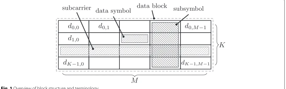
Fifth generation (5G) networks will face new challenges that will require a higher level of flexibility from the physi-cal layer (PHY). 3D and 4k video will push the throughput and spectral efficiency. Tactile Internet [1] will demand latencies at least one order of magnitude smaller than what fourth generation (4G) can achieve. Machine type communication (MTC) [2] will require loose synchroniza-tion, low power consumption and a massive number of connections. Wireless Regional Area Network (WRAN) [3] needs to cover wide areas to provide Internet access in low populated regions. The future mobile networks must have a flexible PHY to address several different scenarios. Generalized Frequency Division Multiplexing (GFDM) [4] is a recent waveform that can be engineered to address various use cases. GFDM arranges the data sym-bols in a time-frequency grid, consisting ofM subsym-bols andK subcarriers, and applies a circular prototype
*Correspondence: [email protected]
MATLAB code illustrating the presented techniques can be downloaded from https://wwwpub.zih.tu-dresden.de/~vf5gdemo/GFDM/ 1Technische Universität Dresden, Vodafone Chair Mobile Communication Systems, Georg-Schumann-Str. 11, D-01187 Dresden, Germany Full list of author information is available at the end of the article
filter for each subcarrier. GFDM can be easily config-ured to cover other waveforms, such as Orthogonal Fre-quency Division Multiplexing (OFDM) [5] and Single Carrier Frequency Domain Multiple Access (SC-FDMA) [6] as corner cases. The subcarrier filtering can reduce the out-of-band (OOB) emissions, control peak to aver-age power ratio (PAPR) and allows dynamic spectrum allocation. GFDM, with its block-based structure, can reuse several solutions developed for OFDM, for instance, the concept of a cyclic prefix (CP) to avoid inter-frame interference. Hence, frequency-domain equalization can be efficiently employed to combat the effects of multi-path channels prior to the demodulation process. With these features, GFDM can address the requirements of 5G networks.
The main disadvantage of a flexible waveform is the complexity required for its implementation. Reducing the GFDM complexity is essential to bring its flexibil-ity to 5G networks. The understanding of GFDM as a filtered multicarrier scheme leads to a modem imple-mentation based on time-domain circular convolution for each subcarrier, performed in the frequency domain [4].
This paper follows the well-known polyphase implemen-tation of filter bank modulation [5–7] and applies it to GFDM.
As one main contribution, the investigation in this paper reveals that the Poisson summation formula [8] can be utilized in the demodulation process, consider-ing a per-subsymbol circular convolution and decima-tion in the frequency domain. This operadecima-tion can be performed as an element-wise multiplication with subse-quent simple M-fold accumulation in the time domain. This simple re-orientation of the data symbol process-ing allows for a considerable reduction in complex-ity, which makes GFDM applicable in a wide range of scenarios.
This paper also contributes to reformulate the modula-tion and demodulamodula-tion as matrix-vector operamodula-tions based on M(K)-point discrete Fourier transforms (DFTs). As an outcome, it becomes evident that DFT can actu-ally be considered as a precoding operation. Moreover, they can be replaced by other transformations as well. This observation facilitates arbitrary precoding of the GFDM data, which adds a new level of flexibility to the system, which will be exemplified by the use of three different transforms: (i) Walsh-Hadamard transform (WHT) [9]; (ii) constant amplitude zero auto-correlation (CAZAC) [10] and; (iii) discrete Hartley transform (DHT) [11].
It is worth mentioning that the proposed low com-plexity signal processing complements the work in [4] because the requirement for block alignment is loos-ened. It can be usable for supporting pipeline inner receiver implementations, particularly when building syn-chronization and channel estimation circuits for embed-ded training sequences [12, 13]. It can also be beneficial to develop future non-linear and recursive detection algorithms.
The remainder of this paper is organized as follows: Section 2 describes the classical approach for GFDM modulation and demodulation and introduce reformu-lated expressions for a less complex implementation. Section 3 presents the matrix notation to describe the modulation and demodulation processes. Section 4 intro-duces precoding to the GFDM communication chain. Section 5 shows the complexity analysis of the precoded schemes. Section 6 brings three examples of precoding using different unitary transforms and Section 7 con-cludes the paper.
2 Classical GFDM description and low-complexity reformulation
Consider a wireless communication system that transmits data in a block-based structure that consists ofK subcar-riers andMsubsymbols. LetN=KMbe the total number of data symbols in the block anddk,m,k = 0,. . .,K−1,
m=0,. . .,M−1, denote the complex valued data symbol that is transmitted on thekth subcarrier andmth subsym-bol. The classical description of GFDM signal generation [14] is given by carried out with period N andg[n] denotes the impulse response of the transmit prototype filter.
The subcarrier filtering does not guarantee orthogonal-ity between subcarriers, unless specific prototype filters are used, such as the Dirichlet pulse [15]. Offset Quadra-ture Amplitude Modulation (OQAM) mapping can also be employed to achieve real-orthogonality [16] and avoid self-interference. In a more general case, the demodulator needs to deal with self-interference. Matched filter (MF) can be combined with successive interference cancella-tion (SIC) [17] or, alternatively, the self-interference can be mitigated with zero-forcing (ZF) or minimum mean square error (MMSE) filters, for which a simple design based on the Zak transform is available [18].
Using theN-point DFTFN, (1) can be carried out as
This leads to the low-complexity modulator implementa-tion described in [4]. Now, expressing the convoluimplementa-tion in (1) explicitly, the transmission equation can be reformu-lated as [6]
The sequence obtained from the Inverse Discrete
Fourier Transform (IDFT) is concatenated M times in
Assuming a flat and noiseless channel, the convolution
With the help of DFT, (5) can be rewritten as
ˆ example, this leads to the low-complexity demodulator implementation described in [4] for the MFγ[n]=g[n], which was later extended to more general filter types in [18]. Now, directly expressing the convolution and sam-pling in (5) leads to the time-domain multiplication
ˆ
where the N-point DFT is only evaluated at everyMth sample. According to the Poisson summation formula [8], this can be reduced to a NM =Kpoint DFT
Equation 7 describes a sampled short-time Fourier transform (STFT). This is clear since the GFDM demodu-lator is actually performing a Gabor transform [18], which can be understood as a sampled STFT. For this reason, (7) does not allow to employ different prototype filters per
subcarrier. This constraint is circumvented by perform-ing equalization before demodulation or the presented scheme can be used to initially access the channel state information by demodulation of training data. Also, the proposed scheme facilitates the implementation of odd number of subsymbols [18] avoiding the use ofM-point DFT and IDFT required in [4].
Notice that (7) holds when MF, ZF or MMSE filters are used. ZF or MMSE filters can deliver good symbol error rate (SER) performance, while MF needs SIC to remove the SER floor caused by the self-interference. Hence, (7) shall be used to implement ZF and MMSE demodulators, while MF can be considered when the transmit filters are orthogonal or OQAM is employed.
3 GFDM matrix model
Arranging the data symbols dk,m in a two-dimensional
structure leads to the data matrix
D=dc0 dc1 · · · dcM−1,= symbols transmitted in themth subsymbol.
According to the GFDM description in Section 2, the rows and columns correspond to the time and frequency resources in Fig. 1, respectively. Hence, thekth row ofD represents the data symbols transmitted in the kth sub-carrier, drk = dk,0 dk,1 . . . dk,M−1
. The time-domain circular convolution of the modulation process can be expressed in the frequency domain as [4]
x= 1
For each subcarrier, the data vector is taken to the fre-quency domain by theM-point DFT matrixWM. The
cor-responding time domain up sampling operation is realized
in the frequency domain by duplicating the transformed data symbols vectorsKtimes, using the repetition matrix R(K,M)=1K,1⊗IM, whereIMis anMsize identity matrix,
1i,jis ai×jmatrix of ones and⊗is the Kronecker
prod-uct. Each subcarrier is then filtered withG=diag(WNg),
where diag(•) returns a matrix that contains the argu-ment vector on its diagonal and zeros otherwise andgis the vector containing the transmit filter impulse response. An up-conversion of the kth subcarrier to its respective subcarrier frequency is performed by the shift matrix
P(k)=!p(k)"⊗IM, (11)
where (•) returns the circulant matrix based on the input vector andp(k)is a column vector where thekth ele-ment is 1 and all others are zeros. TheKsubcarriers are summed and transformed back to the time domain with WHN to compose the GFDM signal. On the demodulator side, the recovered data symbols for thekth subcarrier are given by
whereyis the equalized vector at the input of the demod-ulator, = diag(WNγ) withγ being the demodulation
filter impulse response, e.g., MF, ZF, or MMSE filters. The modulation and demodulation processes can be simplified just by changing the processing order of the data symbols, as derived in (4). In this new matrix model, the GFDM vector is given by
x=
M−1 m=0
P(m)diag(g)R(M,K)WHKdcm. (13)
Observe that (13) is similar to a polyphase filter struc-ture, but with the difference that cyclic time-shifts are used here and frequency domain convolution is per-formed in time domain as element-wise vector multi-plication. With this approach, the first step is to obtain a time domain version of dcm by multiplying it with an inverse DFT (IDFT) matrixWHK.Mtimes upsampling in frequency domain is performed in time by duplicating the transformed data symbols with a repetition matrix R(M,K). Each subsymbol is then pulse-shaped withg.P(m) shifts themth subsymbol to its respective position in time. The GFDM signal is obtained by summing all the pulse-shaped subsymbols, with no need of theN-IDFT domain conversion in (10).
The demodulation operations are also simplified by using the circular-convolution in frequency domain, leading to
While the new approach describing GFDM modula-tion and demodulamodula-tion as convolumodula-tion in the frequency domain reduces the implementation complexity; in the next section, this principle will be expanded to a more general structure, where domain conversions will be understood as a precoding process.
4 DFT-based precoding for GFDM
Equations (13) and (14) bring a new interpretation of the GFDM chain that further increases the flexibility of this waveform. Let the transmit vector from (13) be redefined as
is the information coefficient vector to be transmitted and Tis a transformation matrix. For classical GFDM, where a time-frequency grid is used to transmit the informa-tion,T = WHK. However, (16) can be seen as precoding the information vector by a generic matrix T. Different matrices can be used to achieve different requirements. Hence, by transmitting precoded data, GFDM can be even more flexible to address requirements of future wireless networks.
On the receiver side, the recovered coefficients are given by
The estimated data symbols are obtained by reverting the precoding operation on (17), leading to
ˆ
dcm=Sδˆm. (18)
where S removes precoding. For conventional GFDM,
S=WK. A block diagram that describes the proposed
GFDM modem is presented in Fig. 2. The demodula-tion part can be implemented to run continuously, which can be used for tracking specific properties of the esti-mated information coefficient vectorδˆmcontaining
train-ing data.
The precoding concept can be enlarged to embrace any transform taking into account the two dimensions of the GFDM data blockD, which is defined as a time-frequency grid spanning over several subcarriers and subsymbols, as depicted in Fig. 1. Hence, in the default configuration, the columns of the matrix contain data defined in the frequency domain, while the rows have data in the time domain. The precoded data blockcan be generalized to
a)
b)
Fig. 2Block diagram of low-complexity modulator and demodulator with precoding
where D is now a data block defined in an arbitrary
domain,Tcis aK byK precoding matrix applied to the
columns and Tr is a Mby Mprecoding matrix applied
to the rows ofD. For instance, choosingTcandTrto be
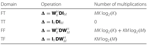
Fourier matrices yields four domains for the GFDM data block,as given in Table 1 , where the frequency-time (FT) domain corresponds to standard GFDM.
The choice of the data domain has impact on the robust-ness of the system regarding time- and frequency- selec-tive fading. The concept is not limited to DFT and, in general, any meaningful transform can be applied to the rows and columns, as exemplified in Section 5.
Taking the concept one step further, (19) can be formu-lated as
vec()=vec(TcDTr). (20)
With the help of the Kronecker product, the right part of (20) can be expressed as
vec(TcDTr)=
!
TTr ⊗Tc
"
vec(D). (21)
The resulting matrix
T =!TTr ⊗Tc
"
(22)
can be seen as an even more general way of precoding that is not restricted to subcarriers or subsymbols but allows arbitrary coupling between any elements ofd = vec(D). The precoding is then applied leading toδ=Td.
5 Out of band, PAPR and complexity analysis The special precoding examples presented in Section 4 can have specific applications. The FT mode allows for
Table 1Precoding in time (T) and frequency (F) domains
Domain Operation Number of multiplications
FT =WH
KDIM MKlog2(K)
TT =IKDIM 0
FF =WH
KDWHM MKlog2(K)+KMlog2(M)
TF =IKDWHM KMlog2(M)
use of null subsymbols and subcarriers to support non-continuous bands, achieving a low OOB radiation as shown in Fig. 3. The time-time (TT) case leads GFDM to become a single-carrier system occupying the whole sys-tem bandwidth. This precoding is especially beneficial for power-limited systems that cannot afford complex signal processing. Another beneficial aspect of the TT precod-ing is the low PAPR, as can be observed in Fig. 3. In contrast, frequency-frequency precoding (FF) results in a DFT-precoded GFDM system, with a spectrum sim-ilar to OFDM. In FF mode, data is defined directly in the frequency domain, according to (3). In this case, one data symbol occupies no more than two frequency bins, assuming a bandlimited transmit filter, such as raised cosine. This property simplifies equalization, as only ICI remains, but on the other hand reduces frequency diver-sity in channels with strong frequency selectivity. Finally, time-frequency precoding (TF) also corresponds to the single carrier, but with symbols spread in time, creating potential for exploiting time diversity.
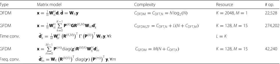
The complexity of the precoding operation of the GFDM transceiver based on DFT algorithms are evalu-ated in Table 1. The number of complex valued multi-plications, a costly operation in implementations, is the chosen criterion for the analysis. The comparison is
car-ried out under the assumption that N = KM complex
data symbols are transmitted. As the baseline for the com-parison in Fig. 3,MNmultiplications from (17) are added to the precoding operations and the OFDM algorithm requires naturally the complexity of a DFT operation, withNlog2(N)multiplications. For purposes of compar-ison, Table 2 also shows an example assuming a scenario equivalent to Long-Term evolution (LTE) with 20 MHz bandwidth [19]. On the receiver side, the GFDM signal is demodulated with a ZF filter [17], which is a worst-case scenario, since the benefits from a sparse frequency response cannot be harvested.
Fig. 3OOB, PAPR and complexity analysis for precoded GFDM. FT/FF:M=16,Mon=15,K=128,Kon=75, TT/TF:K=1,M=1200, OFDM: N=2048,Non=1200
from a DFT operation. Even when the frequency response of the demodulation filter is assumed to be sparse, e.g., when roll-off is small and a ZF filter spanLcan be smaller than the total number of subcarriers, the modem scheme presented in this paper is less complex than the solution proposed in [4]. Another obstacle for the implementation in [4] is that it is basedM-point DFT operations and M is optimally chosen to be odd as shown in [18]. Hence, DFT of odd length would need to be implemented which cannot be achieved by radix-2 FFT algorithms.
Recently, an alternative formulation for low-complexity implementation of GFDM modulators and demodulators was shown in [20]. The presented algorithm relies on a block-diagonalization of the transmitter and receiver matrix by using a block-DFT matrix, which can be easily implemented by means of the FFT. The achieved complex-ity statistics in [20] are comparable to the ones presented in the present paper. However, [20] relies on a specific structure of the transmitter and receiver filters, such that the diagonalization can be employed. Fortunately, at the receiver, this structure is obeyed for MF, ZF and MMSE receiver filters. However, the solution is not general in the sense that any filter at the receiver can be employed with the algorithm in [20]. For example, different filters might be employed when the channel noise is correlated,
polluted by interference or not all subcarriers are allo-cated. In contrast, the algorithm presented in this paper does not rely on any structure of the receiver filter and hence equally works with any time-domain functionγ[n] in (5). This is achieved by smartly rearranging the terms in (5) without making any assumptions onγ[n].
6 Expanding GFDM features with unitary transform precoding
Several different unitary transforms can be associated with GFDM to achieve specific goals. Three examples based on WHT, CAZAC, and DHT will be explored in the following.
6.1 WHT-GFDM
WHT can be combined with GFDM [9] to increase the system robustness against frequency-selective channels. In this case, the WHT is applied to the data symbols on each subsymboldcm, leading to
δm=
1
√
KW
H
KKdcm, (23)
where
K =
K/2 K/2 K/2 −K/2
(24)
Table 2Number of multiplications of DFT models. Modulation and demodulation complexity are the same with this criterion
Type Matrix model Complexity Resource # op.
OFDM x= N1WH
Nd,dˆ=WNy COFDM=CDFT,N=Nlog2(N) K=2048,M=1 22,528
GFDM x= N1WH
N K#−1
k=0
P(k)GR(K,M)WMdr
k CGFDM,ZF=CDFT,N+L(N+CDFT,M) K=128,M=15 274,202
Time conv. dˆrk=M1WMHR(K,M)TP(k)TWNy,∀k L=K
GFDM x=
M#−1
m=0
P(m)diag(g)R(M,K)WHKdcm CGFDM=M(N+CDFT,K) K=128,M=15 42,240
Freq. conv. dˆcm=WK
with 1 = (1) is the Walsh-Hadamard matrix. Notice
that, in this case,
T= √1
KW
H
KK (25)
and (15) can be used to generate the WHT-GFDM symbol. On the receiver side, (17) can be used to obtain the recovered coefficients and the reverse precoding matrix
S= √1
KKWK (26)
is used to obtain the received data vectors, i.e.,
ˆ
The CAZAC transform is a unitary transform where the coefficients of its matrix are given by [21]
[CK]i,l=
Like the WHT, the CAZAC matrix can be used to pre-code the data symbols in the GFDM system. In this case, the coefficient vector transmitted by the CAZAC-GFDM system is given by [10]
δm=WHKCKdcm. (29)
Therefore, the precoding matrix for the CAZAC-GFDM is given by
T=WHKCK (30)
and the inverse precoding matrix is
S=CHKWK. (31)
The recovered data symbols are given by
ˆ
dcm=Sδˆm=CHKWKδˆm. (32)
6.3 DHT-GFDM
The discrete Hartley transform (DHT) is a linear unitary transform with matrix coefficients given by [11]
[K]i,j=
DHT can be combined with GFDM, leading to the following precoding coefficients
δm=WHKKdcm. (34)
The precoding and inverse precoding matrices are given by
T=WHKK
S=TKWK,
(35)
respectively. Therefore, the recovered data symbols can be written as
ˆ
dcm=Sδˆm=TKWKδˆm. (36)
6.4 Precoding performance analysis
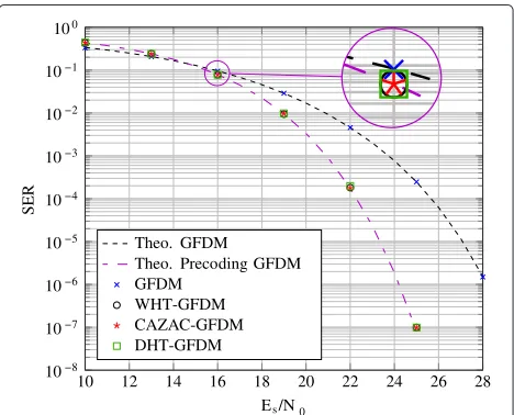
The main advantage of the precoding schemes presented in this section is that each subcarrier carries a linear combination of all data symbols from a given subsymbol. This procedure spreads the information over all subcar-riers, allowing the receiver to exploit frequency diversity. Since the columns and rows of the precoding matrices are orthogonal to each other, the data symbols can be recovered on the receiver side without self-interference introduced by the precoding operation. Therefore, the precoding GFDM schemes experience a performance gain over conventional GFDM in frequency-selective chan-nels, as can be seen in Fig. 4. The parameters used for simulation are presented in Table 3.
The theoretical symbol error rate for GFDM is given by [17]
Es is the average energy per symbol of the
quadra-ture amplitude modulation (QAM) constellation,RTis the
throughput efficiency reduction due to CP,N0is the noise
10 12 14 16 18 20 22 24 26 28
Table 3Simulations parameters
Parameter Value
Modulation order 16-QAM
Number of subcarriers 512
Number of subsymbols 5
CP length 16 samples
Transmit filter RC withα=0.25
Channel impulse response hdB[i]= −2i/3 fori=0, 1,. . ., 15
spectral density andξlis the noise enhancement factor per
subcarrier, which is given by
ξl=
1 MK
MK−1 k=0
GH[−[kk]]2, (39)
with H[k] and G[k] being the channel frequency response and the prototype filter frequency response, respectively.
Equation (37) can also be used to estimate the symbol error rate for precoding GFDM using unitary transform [9] but, in this case,
γl=
3|Heq|2RT
2(2μ−1) · Es
ξlN0
, (40)
where
Heq=
$ 1 MK
MK−1 k=0
1
|H[k]|2 %−1
2
, (41)
andξlmust be redefined as
ξl= MK−1
i=0
[A(IM⊗T)]−l,i1 2
. (42)
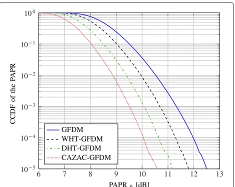
Another benefit that is obtained by precoding the data symbols before the GFDM modulation is the PAPR reduc-tion, as can be seen in the complementary cumulative density function (CCDF) curves shown in Fig. 5. Since the subcarriers carry a weighted average of all data symbols from a given subsymbol, the probability of achieving high amplitude peaks is reduced, leading to a small PAPR when compared with conventional GFDM. Here, the employed precoding matrix affects the achieved PAPR. The best PAPR reduction is achieved by the CAZAC transform, followed by DHT and WHT, respectively. The explana-tion for this behavior lies on the aperiodic autocorrelaexplana-tion function [10] of the coefficientsδm. CAZAC transforms
lead to coefficients with smaller aperiodic autocorrelation sidelobes. This property leads to a lower PAPR for the CAZAC-GFDM.
6 7 8 9 10 11 12 13
10− 5
10− 4
10− 3
10− 2
10− 1
100
PAPR0[dB]
CCDF
of
the
P
APR
GFDM WHT-GFDM DHT-GFDM CAZAC-GFDM
Fig. 5CCDF of the GFDM PAPR with and without precoding
7 Conclusions
This paper introduces a GFDM modulator and demod-ulator based on a low-complexity multiplication in the time domain. The new matrix model allows to consider the coefficients transmitted by the subcarriers as the precoding of the data symbols. This approach broadens the GFDM flexibility, allowing to use different trans-forms to achieve different goals. Precoding can be used to improve the system SER performance over frequency-selective channels and to reduce the PAPR. The three unitary transforms considered in this paper presented the same SER performance. The CAZAC-GFDM achieved the lowest PAPR among the considered transforms. The com-putational complexity of the new GFDM modulator and demodulator have been compared with the solution pro-posed in [4], showing that the modem solution propro-posed in this paper can reduce the number of complex valued multiplications, even when sparse filters in the frequency domain are employed.
Competing interests
The authors declare that they have no competing interests.
Acknowledgements
This work has been performed in the framework of the FP7 ICT-619555 project RESCUE, which is partly funded by the European Union. The work presented in this paper was sponsored by the Federal Ministry of Education and Research within the progarmme “Twenty20 - Partnership for Innovation” under contract 03ZZ0505B - “fast wireless” and within in the framework of the SATURN project with contract no. 100235995 which is funded by the Europaischer Fonds Für regionale Entwicklung (EFRE). This work was partially supported by Finep/Funttel Grant No. 01.14.0231.00, under the Radiocommunication Reference Center (Centro de Referência em Radicomunicações - CRR) project of the National Institute of Telecommunications - Inatel, Brazil. The
computations were performed at the Center for Information Services and High Performance Computing (ZIH) at TU Dresden.
Author details
1Technische Universität Dresden, Vodafone Chair Mobile Communication
Nacional de Telecomunicações, Av. João de Camargo, 510, 37540-000 Santa Rita do Sapucai, MG, Brazil.
Received: 19 February 2016 Accepted: 8 May 2016
References
1. GP Fettweis, The tactile internet: applications and challenges. IEEE Veh. Technol. Mag.9(1), 64–70 (2014)
2. P Marsch, B Raaf, A Szufarska, P Mogensen, H Guan, M Farber, S Redana, K Pedersen, T Kolding, Future mobile communication networks: challenges in the design and operation. IEEE Veh. Technol. Mag.7(1), 16–23 (2012)
3. H Kim, J Kim, S Yang, M Hong, Y Shin, An effective mimo-ofdm system for ieee 802.22 wran channels. IEEE Trans. Circ. Syst. II Express Briefs.55(8), 821–825 (2008)
4. I Gaspar, et al., inIEEE 77th Vehicular Technology Conference (VTC Spring). Low Complexity GFDM Receiver Based On Sparse Frequency Domain Processing, (2013). http://ieeexplore.ieee.org/xpls/abs_all.jsp?arnumber= 6692619&tag=1
5. B Farhang-Boroujeny, OFDM versus filter bank multicarrier. IEEE Signal Proc. Mag.28(3), 92–112 (2011)
6. P Banelli, S Buzzi, G Colavolpe, A Modenini, F Rusek, A Ugolini, Modulation formats and waveforms for 5G networks: who will be the heir of OFDM?: an overview of alternative modulation schemes for improved spectral efficiency. IEEE Signal Proc. Mag.31(6), 80–93 (2014)
7. M Renfors, J Yli-Kaakinen, FJ Harris, Analysis and design of efficient and flexible fast-convolution based multirate filter banks. IEEE Trans. Signal Proc.62(15), 3768–3783 (2014)
8. J Benedetto, G Zimmermann, Sampling multipliers and the poisson summation formula. J. Fourier Anal. Appl.3(5), 505–523 (1997) 9. N Michailow, L Mendes, M Matthe, I Gaspar, A Festag, G Fettweis, Robust
WHT-GFDM for the next generation of wireless networks. IEEE Commun. Lett.19(1), 106–109 (2015)
10. R Qiu, Z Wu, S Zhu, in4th International Conference on Wireless Communications, Networking and Mobile Computing. A novel paper reduction method in OFDM systems by using Cazac matrix transform, (2008), pp. 1–4. http://ieeexplore.ieee.org/xpls/abs_all.jsp?arnumber= 4678106
11. S Bouguezel, MO Ahmad, MNS Swamy, Binary discrete cosine and Hartley transforms. IEEE Trans. Circ. Syst. I Regular Papers.60(4), 989–1002 (2013) 12. I Gaspar, A Festag, G Fettweis, in82nd Vehicular Technology Conference
(VTC Fall). Synchronization using a pseudo-circular preamble for generalized frequency division multiplexing in vehicular communication, (2015), pp. 1–5. http://ieeexplore.ieee.org/xpls/abs_all.jsp?arnumber= 7391164
13. I Gaspar, A Festag, G Fettweis, inIEEE Global Communications Conference (GLOBECOM 2015). An embedded midamble synchronization approach for generalized frequency division multiplexing, (2015), pp. 1–5. http:// ieeexplore.ieee.org/xpls/abs_all.jsp?arnumber=7417357
14. N Michailow, I Gaspar, S Krone, M Lentmaier, G Fettweis, inIEEE International Symposium on Wireless Communication Systems (ISWCS). Generalized Frequency Division Multiplexing: analysis of an alternative multi-carrier technique for next generation cellular systems, (2012), pp. 171–175. http://ieeexplore.ieee.org/xpls/abs_all.jsp?arnumber= 6328352
15. M Matthé, et al., inIEEE International Conference on Communications Workshops (ICC). Influence of pulse shaping on bit error rate performance and out of band radiation of generalized frequency division multiplexing, (2014), pp. 43–48. http://ieeexplore.ieee.org/xpl/articleDetails.jsp? arnumber=6881170&filter%3DAND%28p_IS_Number%3A6881162%29 16. H Lin, P Siohan, Multi-carrier modulation analysis and WCP-COQAM
proposal. EURASIP J. Adv. Signal Process.2014(79), 1371–1430 (2014) 17. N Michailow, et al., Generalized frequency division multiplexing for 5th
generation cellular networks. IEEE Trans. Commun.62(9), 3045–3061 (2014)
18. M Matthe, LL Mendes, G Fettweis, Generalized frequency division multiplexing in a Gabor transform setting. IEEE Commun. Lett.18(8), 1379–1382 (2014)
19. I Gaspar, et al., in11th International Symposium on Wireless Communications Systems (ISWCS). LTE-compatible 5G PHY based on Generalized Frequency Division Multiplexing, (2014), pp. 209–213. http://ieeexplore. ieee.org/xpl/login.jsp?tp=&arnumber=6933348&url=http%3A%2F %2Fieeexplore.ieee.org%2Fxpls%2Fabs_all.jsp%3Farnumber%3D6933348 20. A Farhang, N Marchetti, LE Doyle, Low Complexity Modem Design for
GFDM. IEEE Trans. Signal Process.PP(99), 1–1 (2015). doi:10.1109/TSP.2015.2502546
21. J Meng, G Kang, inInternational Conference on Computer Application and System Modeling (ICCASM). A novel ofdm synchronization algorithm based on cazac sequence, vol. 14, (2010), pp. 14–63414637. http://ieeexplore. ieee.org/xpl/login.jsp?tp=&arnumber=5622219&url=http%3A%2F %2Fieeexplore.ieee.org%2Fxpls%2Fabs_all.jsp%3Farnumber%3D5622219
Submit your manuscript to a
journal and benefi t from:
7Convenient online submission
7 Rigorous peer review
7Immediate publication on acceptance
7 Open access: articles freely available online
7High visibility within the fi eld
7 Retaining the copyright to your article