R E S E A R C H
Open Access
Adaptive hierarchical modulation and power
allocation for superposition-coded relaying
Hirofumi Yamaura, Megumi Kaneko
*, Kazunori Hayashi and Hideaki Sakai
Abstract
We propose a relaying scheme based on superposition coding (SC) with discrete adaptive modulation and coding (AMC) for a three-node wireless relay system, based on half duplex transmission, where each node decodes messages by successive interference cancelation (SIC). Unlike the previous works where the transmission rate of each link is assumed to achieve Gaussian channel capacity, we design a practical superposition-coded relaying scheme with discrete AMC while taking into account the effect of decoding errors at each stage of the SIC process at each node. In our scheme, hierarchical modulation (HM) is used to create an SC message composed of one basic and one
superposed message with optimized power allocation. We firstly introduce the proposed scheme without forward error correction (FEC) for high signal-to-noise ratio (SNR) region and provide the optimal power allocation between the superimposed messages. Next, we extend the uncoded scheme to incorporate FEC to overcome bad channel conditions. The power allocation in this case is based on an approximated expression of the bit error rate (BER). Numerical results show the performance gains of the proposed SC relaying scheme with HM compared to conventional schemes, over a large range of SNRs.
1 Introduction
Cooperative relaying is a recently developed technique that enables to enhance the overall performance of wire-less communication systems in terms of transmission rates and coverage by exploiting spatial diversity [1,2]. In cooperative relaying systems, one or more relay nodes assist the data transmission from the source node to the destination node. Due to the broadcast nature of the wire-less medium, relays can receive the signal sent by the source and, in turn, forward their processed version of the signal to the destination. At the destination, the signals received from the relays (and possibly from the source) are combined for improving the received signal-to-noise ratio (SNR). A number of cooperative relaying schemes have been proposed for half-duplex relays that either transmit or receive the signal but cannot do both at the same time. There are two major types of relaying protocols: amplify-and-forward (AF) and decode-amplify-and-forward (DF) [3]. In the AF protocol, relays amplify the received signal and transmit it to the destination. This protocol has advan-tages on complexity and cost due to its simple design. *Correspondence: [email protected]
Graduate School of Informatics, Kyoto University, Yoshida Honmachi, Sakyo-ku, Kyoto, 606-8501, Japan
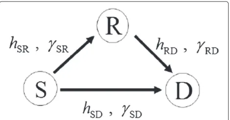
However, noise is also enhanced by the relays. In the DF protocol, the relays decode the received signal before for-warding it to the destination. Although the relays require higher capabilities, this protocol can mitigate the effects of noise in the source to relay links. Moreover, the relays can employ adaptive modulation and coding (AMC) in the relay to destination links, which is one of the notable advantages of the DF protocol. In this paper, we con-sider the three-node wireless relay system composed of one source, one destination, and one relay as shown in Figure 1, where the relay operates according to DF pro-tocol. For such a system, authors in [4-6] have proposed cooperative relaying schemes. In the cooperative diver-sity (CD) scheme of [4], the destination uses maximum ratio combining (MRC). In [5,6], the destination decodes the combined direct and relayed signals by using the log-likelihood ratio (LLR) for each bit, allowing the source and relay to use different modulation rates.
Recently, a cooperative DF relaying scheme based on superposition coding (SC) has been proposed in [7,8] for the three-node wireless relay system. SC was originally introduced in [9,10] for the broadcast channel, where mul-tiple users are served simultaneously by a single source. The source superimposes the messages for the users with
Figure 1The three-node wireless relay system.
a certain power allocation and broadcasts the resulting signal. Then, successive interference cancelation (SIC) is performed by each user, where the messages intended for users with weaker channel are decoded first, then sub-tracted from the received signal, prior to decoding their own message. It was shown in [9,10] that SC with SIC actually achieves the capacity of the Gaussian broadcast channel. In the scheme of [7,8], the source generates the SC message composed of one basic and one superposed message, both of which are destined to the destination, and transmits it in the first time slot with an adequate power allocation between the two messages. In the sec-ond time slot, after decoding both messages using SIC, the relay forwards only the superposed message to the destination, reducing the relay transmission time and enhancing the overall rate. Using the superposed message decoded correctly, the destination subtracts the contri-bution of the superposed message from the direct signal received in the first time slot and decodes the basic mes-sage from the resulting signal. It is shown that this SC scheme outperforms conventional relaying schemes by using optimum power allocation under the assumption that the transmission rate of each link achieves Gaus-sian channel capacity. However, practical wireless systems make use of discrete modulation and coding, in which case the analysis in [7] based on the assumption of Gaus-sian channels is not applicable. Although an example of implementation with discrete modulation was considered in [8], no power optimization nor channel coding was con-sidered. Thus, the design of a new scheme with optimized power allocation and modulation/coding is required in order to benefit from SC relaying under such practical constraints.
In this paper, we propose a practical superposition-coded relaying scheme using discrete AMC for the three-node wireless relay system. In order to create an SC message, we make use of hierarchical modulation (HM) [11,12]. HM is the technique adopted by digital TV broadcasting that enables to embed two independent bit-streams, a low-priority one and a high-priority one, using
discrete modulations [11]. We first introduce the uncoded SC scheme of [13] with discrete HM, for which we pro-vide here the full analysis for optimizing the power allo-cation between the two superimposed messages. Such an uncoded scheme can attain better performance over coded schemes in the high SNR regime, since the redun-dancy introduced by coding becomes useless whenever there are no errors. Next, we extend our uncoded SC scheme in [13] to incorporate FEC technique for over-coming bad channel conditions. In this case, due to the difficulty to derive a theoretical formula for the bit error rate (BER) of decoded messages, we make use of an approximate expression of the BER to perform power optimization. We consider the low-density parity-check (LDPC) code as it can provide a performance close to the Shannon limit [14,15], although other coding tech-niques can be considered as well. The extensive simulation results show the performance gains provided by the pro-posed uncoded and coded SC schemes with discrete HM, compared to reference CD schemes.
The paper is organized as follows: Section 2 presents the system model, and Section 3 introduces our proto-col. In Sections 4 and 5, the throughput expressions of our scheme are derived, and the optimal power alloca-tion, which maximizes the throughput, is analyzed for both uncoded and LDPC-coded cases. Section 6 presents the numerical results and discussions. Finally, conclusions and directions for future work are given in Section 7.
2 System model
We consider the wireless relay system which consists of three nodes: source S, relay R, and destination D which are shown in Figure 1.
Relay R is assumed to use DF protocol and to be half duplex, i.e., it cannot transmit and receive simultaneously. We assume separate power constraints at nodes S and R as in [3]a.
Thus, if node S transmits a vector ofN symbolsx = [x(1),. . .,x(N)]T, nodes D and R receive
yD1=hSDx+zD1, (1)
yR=hSRx+zR, (2)
respectively. The vector ofMsymbolsxR = [xR(1),. . ., xR(M)]Tbeing transmitted from node R, and the received
signal at node D is
yD2=hRDxR+zD2. (3)
In (1), (2), and (3), hi(i ∈ {SD, SR, RD}) denotes the
complex channel coefficient of links SD, SR, and RD, respectively, while zj(j ∈ {R, D1, D2}) are vectors of
Table 1 Discrete AMC table: uncoded case
Modulation BPSK QPSK 16-QAM
Rate (b/s/Hz) 1 2 4
SNR threshold (dB) 6.5 10.5 17
γi= | hi|2
σ2 , i∈ {SD, SR, RD}. (4)
All channel coefficientshi(i∈ {SD, SR, RD})and hence
instantaneous SNRs are assumed to be constant during each frame consisting of the two steps. However, they undergo flat Rayleigh fading from frame to frame. Node S is assumed to knowγSDandγSR, and node R is assumed
to knowγRD. Both S and R transmit signals with an
aver-age power E[|x(n)|2]= 1 (n = 1,. . .,N). Finally, the
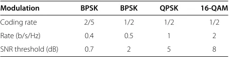
bandwidth of each link is assumed to be normalized to 1. Two types of transmissions will be considered: the uncoded and LPDC coded cases with the discrete mod-ulations specified in Tables 1 and 2, respectively. In the uncoded case, the SNR thresholds for each modulation level are derived as in [16], for a target BER of 10−3. On the other hand, the SNR thresholds for the LDPC-coded case are derived based on the frame error rate (FER) approximation used in [17,18], for a target FER of 10−3.
In addition, the proposed protocol makes use of HM levels 2/4-QAM and 4/16-QAM in the first step, as explained in the next section.
3 Description of the proposed protocol
We introduce the steps of the proposed scheme based on [8] when modulations/coding in Tables 1, 2, and HMs 2/4-QAM 4/16-2/4-QAM are available.
The steps of the proposed scheme are as follows (see Figure 2):
Step 1. Denote a basic message and a superposed message created from information bits at node Sasubandus, respectively. Moreover, we defineL as the number of bits inuborus. In the uncoded scheme, the components ofub andusare mapped to the basic symbolsxb(n) and the superposed symbolsxs(n)
(n=1,. . .,N), respectively. In the coded scheme, the LDPC codewordscbandcsare generated by encodingubandus, respectively.
Table 2 Discrete AMC table: LDPC-coded case
Modulation BPSK BPSK QPSK 16-QAM
Coding rate 2/5 1/2 1/2 1/2
Rate (b/s/Hz) 0.4 0.5 1 2
SNR threshold (dB) 0.7 2 5 8
Figure 2SC-relaying scheme.The arrows represent the signal transmission from a node A to a node B. Step 1 is shown at the left of the broken line, and Step 2 at the right.
Then nodeSmaps the LDPC codewordscband csto the basic symbolsxb(n)and the
superposed symbolsxs(n) (n=1,. . .,N), respectively. Using either 2/4-QAM or 4/16-QAM, nodeSgenerates the following symbol from the basic and superposed symbols
x(n)=√1−αxb(n)+√αxs(n), n=1,. . .,N,
(5) whereαdenotes the power allocation
parameter between the basic symbolxb(n)and the superposed symbolxs(n). If 2/4-QAM is used,xb(n)is an in-phase binary phase shift keying (BPSK) symbol, whilexs(n)is a quadrature-phase BPSK symbol, giving the constellation of the superposed signal shown in Figure 3.
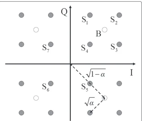
Letr be the coding rate used at nodeS, we thus haveL=rN. It is noted thatr=1is equivalent to the uncoded case. We setα∈(0,12]for 2/4-QAM due to symmetry. On the other hand, when 4/16-QAM is used, bothxb(n)andxs(n) are independent QPSK symbols, giving the constellation shown in Figure 4.
In this case, we haveL=2rN. We assume
α∈(0,12)so that each constellation point stays within the same quadrant as its corresponding basic symbol. Defining vectors of basic and superposed symbols as
xb=[xb(1),. . .,xb(N)]Tand
xs=[xs(1),. . .,xs(N)]T, the received signal at nodeRis given by
yR=hSR √
1−αxb+hSR√αxs+zR. (6) FromyR, nodeRfirst decodesxbby treating √
αxsas noise and then obtains the basic messageubif there is no decoding error. Subtracting√1−αxbfromyR, we obtain
yR=yR−hSR √
1−αxb=hSR √
Figure 3Constellation of the transmitted symbol by nodeS using 2/4-QAM.I represents the in-phase component, and Q the quadrature-phase component. Arrows in broken lines show the power allocated to the basic and superposed symbols.
from whichRdecodesxsand obtains the superposed messageus. On the other hand, nodeDreceives
yD1=hSD √
1−αxb+hSD√αxs+zD1, (8) in the first step, and keeps it in memory. Step 2. Given the link qualities, nodeRtransmits
xR=[xR(1),. . .,xR(M)]T, the remodulated signal ofuscorrectly decoded in step 1. The received signal at nodeDis
yD2=hRDxR+zD2. (9) FromyD2, nodeDdecodesxRand hence obtainsus. NodeDcancels the contribution of xsfromyD1kept in memory in step 1, obtaining
yD1=yD1−hSD√αxs=hSD √
1−αxb+zD1, (10) from whichDfinally decodesxb, obtainingub.
4 Throughput analysis for the uncoded case
4.1 Average throughput
Here, we consider the proposed scheme without FEC. First, we derive the average throughput defined as the number of correct bits received at node D per unit sym-bol time. If at least one bit in the message is not decoded correctly, the whole message is discarded. We define prob-abilitiesQRb,QRs,QDs, andQDbas follows:
QRb=Pr(u¯Rb=ub), (11)
QRs=Pr(u¯Rs=us| ¯uRb=ub), (12) QDs=Pr(u¯Ds=us| ¯uRs=us,u¯Rb=ub), (13) QDb=Pr(u¯Db=ub| ¯uDs=us,u¯Rs=us,u¯Rb=ub),
(14)
whereu¯kb,u¯ks,k ∈ {R, D}represent the basic and
super-posed messages decoded at nodek, respectively; whileub
and us are the original basic and superposed messages,
respectively. In the analysis, we assume that theLbits of the superposed message are correctly received at node D if the basic and the superposed messages have been cor-rectly decoded at node R, and if us has been correctly
decoded at node D. However, in the simulations, all super-posed messages will be forwarded to node D even if they were not correctly decoded at node R, since they may still be correctly decoded at node D. Still, it will be shown in Section 6 that the analytical throughput gives a valid approximation of the actual one. Thus, the expected num-ber of bits that node D correctly receives isLQRbQRsQDs
bits. With a similar calculation for the basic message, the expected number of bits that node D correctly receives after the two steps is equal to LQRbQRsQDsQDb. Since
node S transmits the signal ofN symbols in step 1 and node R transmits the signal ofMsymbols in step 2, the duration of the two steps isN+Msymbol times, giving the average throughput as
RSC =
LQRbQRsQDs(1+QDb)
N+M . (15)
4.1.1 2/4-QAM
We derive the average throughput when node S selects 2/4-QAM in step 1. As both the basic and the superposed symbols are BPSK, we haveL = N in (15). When node R decodesxbfromyR, node R decides the basic symbols xb(n) (n = 1,. . .,N) through BPSK symbol detection.
In 2/4-QAM, basic and superposed symbols are trans-mitted using in-phase and quadrature-phase, respectively.
This means thatQRbis the probability that the message is
decoded correctly with BPSK at the SNRγSR(1−α). Thus,
denoting the probability that each symbol xb(n) (n =
1,. . .,N)is decoded correctly byq, we have
where erfc(x)is the complimentary error function,
erfc(x)= √2 π
∞
x
exp(−t2)dt. (18)
Using (16), we obtain
QRb=qN = {1−PBPSK(γSR(1−α))}N. (19)
After cancelation ofxb, node R decodesxs at the SNR γSRα, giving
QRs= {1−PBPSK(γSRα)}N. (20)
In step 2, node R forwards theNbits to node D using discrete modulations. For clarity of exposition, we will only derive the analysis for QPSK and 16-QAM, since these are the most likely to be used as the relay-destination link is of high quality (otherwise, relaying schemes would be of no use). Moreover, the analysis for BPSK can be derived similarly. Thus, we have M = N2 when QPSK is used, andM = N4 for 16-QAM. Denoting byR the
SNR threshold for switching between QPSK and 16-QAM (from Table 1,R=17 dB),QDsis given by
bol error rate of 16-QAM in AWGN channel with SNRγ
given as [14]
PQPSK(γ )=1−
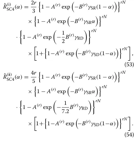
By substituting (19), (20), (21), and (24) into (15), the average throughput with 2/4-QAM denoted byR(SC4i) (α)
for γRD < R and by RSC4(ii) (α) for γRD ≥ R can be
For 4/16-QAM, the average throughput can be derived in a similar way. As both the basic and the superposed sym-bols are QPSK, we have L = 2N in (15). Node R first decodesxbfromyRby treating the components ofxs as
noise, which means that it performs common QPSK sym-bol detection. Here, it should be noted that unlike the case of 2/4-QAM, the interference fromxs degrades the
detection performance. If the basic symbol corresponds to the point B in the first quadrant in Figure 4, the result-ing transmitted 4/16-QAM symbol is one of the points S1,
S2, S3, or S4. Denoting the probabilities that point Sj(j=
1,. . ., 4)is received in the first quadrant byqjand
consid-ering the symmetric property of 4/16-QAM constellation, we have
As q1 is the probability that both in-phase and
quadrature-phase components of the point S1stay in the
first quadrant,q1is given by
Similarly, we obtain
In step 2, node R transmits the information ofN bits to node D using either QPSK or 16-QAM. Thus, we have
M=Nwhen QPSK is used andM= N2 when 16-QAM is
By substituting (32), (33), (34), and (35) into (15), the average throughput with 4/16-QAM denoted byR(SC16i) (α)
for γRD < R and by RSC16(ii) (α) for γRD ≥ R can be
4.2 Optimizing the power allocation
The throughput of the proposed scheme depends on the power allocation parameterα, which is optimized next.
4.2.1 2/4-QAM
First, assuming that node S uses 2/4-QAM in step 1, the problem is to select α ∈ (0, 1/2] that maximizes the throughput RSC4, given N, γSD, γSR, andγRD. It can be
observed that the value ofαmaximizing (25) and (26) does not depend on SNRγRD, since the HM is restricted to 2/4-QAM here. Thus, without loss of generality, we assume
γRD ≥ R. By differentiating (26) with respect to α, we where we define
For 0< α≤ 12, we have 4N
5 QDb(α) N−1
N QDs(α)NN−1QDs>0. (40)
Thus,GSC4(α) = 0 is the necessary condition for an
optimalα. We can prove that the solutions of the equation
GSC4(α) = 0 always exist in 0 < α ≤ 12. By (39), we where limx→c+f(x) represents the right-hand limit of a function f(x) asx approaches c. From (41) and (42), it thus the intermediate-value theorem guarantees the exis-tence of the solution in the considered range. Although it is difficult to prove the uniqueness of the solution for
GSC4(α) = 0 in 0 < α ≤ 12 in the proposed scheme, the
valueαSC4∗ obtained by solving the equationGSC4(α)=0
numerically is used. The numerical results in Section 6 will show that αSC4∗ can maximize the throughput
RSC4(α). 4.2.2 4/16-QAM
A similar analysis applies in the case where node S uses 4/16-QAM in step 1. Here, the problem is to selectα ∈ (0, 1/2) that maximizes the throughputRSC16, given N, γSD,γSR, andγRD. Again, we can see that the value ofα
maximizing (36) and (37) does not depend on SNRγRD, as
the HM is restricted to 4/16-QAM. Thus, we may assume
γRD≥Rwithout loss of generality. By differentiating (37)
with respect toα, we have
where we define
GSC16(α)=
Thus,GSC16(α) = 0 is the necessary condition for an
optimalα. We can prove that the solutions of the equation
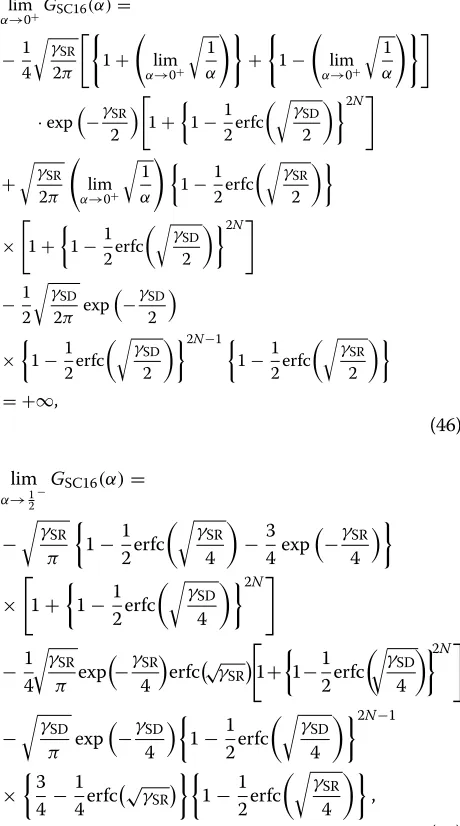
GSC16(α) = 0 always exist in 0 < α < 12. By (44), we
lim where limx→c−f(x) represents the left-hand limit of
a function f(x) as x approaches c. From (46) and (47), it can be seen that limα→0+GSC16(α) > 0
and lim
α→12−GSC16(α) < 0, thus the
intermediate-value theorem guarantees the existence of the solution in the considered range. Again, the proposed scheme chooses the valueα∗SC16obtained by solving the equation
GSC16(α) = 0 numerically which is shown to maximize
the throughputRSC16in Section 6.
5 Throughput analysis for the LDPC-coded case
5.1 Average throughput
In this subsection, we consider the average throughput of our scheme with FEC. When LDPC code is used, it is very difficult to obtain the exact closed-form expressions of BER and FER for the proposed method. So, in this paper, we assume that bit errors are independent of each other within each frame and that each bit has the same BER. We
employ the following FER approximation used in [17,18] to derive the throughput:
FER(γ )≈1− {1−a·exp(−bγ )}, (48) whereis the number of message bits andγ is the SNR. Parametersaandbin (48) are determined by fitting (48) to the FER curve obtained by simulations as explained in Section 6. Here, we consider the coding rates of 12 and
2
5, although any other codes and rates can be similarly
used in the proposed method. We adopt the code length of 64, 800 as in the Digital Video Broadcasting - Satel-lite - Second Generation (DVB-S2) standard. The fitting parametersaandbare shown in Table 3. The parameter
bfor QPSK is half of that for BPSK, since QPSK requires double SNR to achieve the same BER as BPSK. For the same reason, the parameterbfor 16-QAM is obtained by dividing the parameterb for BPSK by 7.2. Thus, we can write the FER approximation for QPSK (16-QAM) by only using the parametersaandbfor BPSK. We will show that these fitting curves provide a good approximation for the FER obtained by simulations in Section 6.
5.1.1 2/4-QAM
We derive the average throughput when node S selects 2/4-QAM in step 1. Here, to simplify the description, we assume that nodes S and R use identical LDPC code. Letr
be the coding rate used at node S, givingL =rN in (15). We defineA(r)=aandB(r)=bas parameters in Table 3 for BPSK modulation and coding rate r. For example, if
r = 12,A(r) = 3.11×10¹²andB(r) = 47.9. Since node R
after canceling the interference from the signalxb, we have QRs =
1−A(r)exp−B(r)γSRα rN
. (50) As for the uncoded case, we describe the analysis for the cases where QPSK or 16-QAM are used at node R in step 2 (the case for BPSK may be derived similarly). In this case,
Table 3 Parametersaandbfor various modulations and coding rates
Modulation Coding rate Parametera Parameterb
the SNR threshold for switching between QPSK and 16-By substituting (49), (50), (51), and (52) into (15), the average throughput for 2/4-QAM denoted byRˆ(SC4i) (α)for
γRD < Rand byRˆSC4(ii) (α)forγRD ≥Rcan be expressed Here, we require the following conditions for the prob-abilities (49), (50), (51), and (52) to have their value in the range of(0,12]:
From the conditions (55) and (56), we have the following inequalities forα:
logA(r)
Since the performance of our scheme has very lim-ited gain when γSD ≤ 0.7 dB, this is not a
restric-tive constraint. Thus with (58), we obtain the range ofα,
For 4/16-QAM, the average throughput can be derived as follows. Here, L = 2rN in (15). Recall that node R decodes xb from the received signal yR with QPSK
symbol detection in step 1, treating xs as noise. In the
uncoded case, each bit of a basic message is mapped to one constellation point of QPSK symbol correspond-ing to the basic message, for example, to point B in Figure 4, for which the interference fromxs
determinis-tically results from points S1, S2, S3, or S4. However, in
the coded case, each message bit is encoded by a gen-erator matrix into a number of coded bits which are mapped into any 4/16-QAM constellation point across all symbols. Due to the difficulty of tracking all the con-stellation points corresponding to each message bit, we take a stochastic approach to approximate the impact of the interference fromxsfor each message bit as follows.
When decoding a basic message bit, we can assume that the overall interference for the message bit results from the aggregation of a large number of interference com-ponents with power α, since the length of the LDPC codeword is very long. Therefore, from the central limit theorem, we can see the interference from xs as
Gaus-sian noise with power ofα. In this way, we can writeQRb
by using the fitting parametersA(r)andB(r) given by the
UsingR,QDsis given by
By substituting (60), (61), (62), and (63) into (15), the average throughput with LDPC-coded 4/16-QAM denoted by Rˆ(SC16i) (α)forγRD < Rand byRˆ(SC16ii) (α)for
Here, we require the follow the conditions for the prob-abilities (60), (61), (62), and (63) to have their values in the range of(0,12]:
From the conditions (66), (67), and (68), we have the following inequalities forα:
α≤
γSD > 4 dB, which again is not a restrictive con-straint. Moreover, γSR satisfies the inequality 2 logA
(r)
. This inequality holds when γSR > 6 dB, the region in which our scheme
achieves significant gains. Thus with (70), (71), and (72), we get the region ofα,
5.2 Optimizing the power allocation
5.2.1 2/4-QAM
First, assuming that node S uses LDPC-coded 2/4-QAM in step 1, the problem is to selectα ∈ (0, 1/2] that max-imizes the throughput RˆSC4, given r, N, γSD, γSR, and γRD. We assumeγRD ≥ Rsince the optimal value ofα
does not depend on SNRγRD. By differentiating (54) with
where we define
optimalα. We can prove that the solutions of the equation
ˆ Although it is difficult to prove the uniqueness of the solu-tion forGˆSC4(α) = 0 inC ≤ α ≤ 12, in the proposed
scheme, the valueαˆSC4∗ obtained by solving the equation
ˆ
GSC4(α)=0 numerically is used. 5.2.2 4/16-QAM
A similar analysis applies in the case where node S uses LDPC-coded 4/16-QAM in step 1. Here, the problem is to selectα ∈ (0, 1/2)that maximizes the throughputRˆSC16,
givenN,γSD,γSR, andγRD. Here, we assumeγRD≥R. By
differentiating (65) with respect toα, we have
dRˆ(SC16ii) (α)
where we define
ˆ
Thus, GˆSC16(α) = 0 is the necessary condition for
ˆ
GSC16(E)=−
1 2B
(r) 1+ 1 γSR
E+γ1
SR 2
1−A(r)exp
−1
2B
(r)γ SRE
·
1+
1−A(r)exp
−1
2B
(r)γ
SD(1−E) 2rN
.
Again, the proposed scheme chooses the value αˆ∗SC16
obtained by solving the equationGˆSC16(α) = 0
numeri-cally.
6 Numerical results
6.1 Reference schemes
We consider three alternatives to the proposed scheme when BPSK, QPSK, and 16-QAM are available for adap-tive modulation:
1. Direct transmission. NodeStransmits to nodeD directly without any help from nodeR. NodeS chooses the modulation and coding rate to achieve the best throughput.
2. Multi-hop (MH) transmission. Only the relayed signal is considered at nodeD, not the direct one. After nodeRdecodes the received signal from nodeS in step 1, it forwards in step 2 the remodulated signal given the SNRγRDof link RD.
3. CD transmission. We consider the CD scheme proposed in [6], where different modulation rates can be used at nodeSand nodeR. In step 1, the signal transmitted by nodeSis received by both nodesR andD. At nodeR, the received signal is demodulated and retransmitted to nodeDin step 2 using the modulation adapted to the SNRγRDof link RD. If nodeRuses the same modulation as in step 1, node Dperforms MRC of the signal received from nodeS in step 1 with the one received from nodeRin step 2 and decodes the combined signal. Otherwise, nodeD decodes the combined signal by using the LLR for each bit before decoding.
6.2 FER approximation
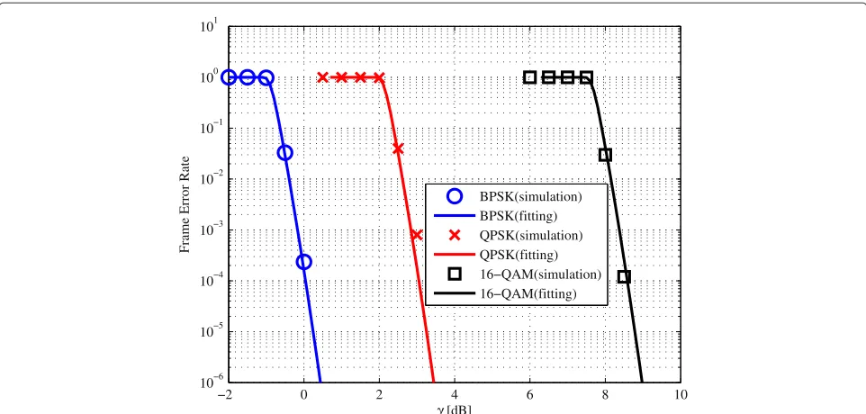
When we use half rate LDPC code and a modulation scheme among BPSK, QPSK, and 16-QAM, the FER obtained by simulations and the FER approximation (48) are compared with respect to γ in Figure 5. Here, the parametersaandbin Table 3 are used. The parametersa
andbare determined as least square solutions by consid-ering the shift and the slope of the simulated BER curve in logarithmic scale, respectively. It is shown that the fitting curve provides a good approximation for the simulated FER for each modulation.
Figure 6 compares the expression (60) with the param-etersaandbfor BPSK in Table 3, namely,A(r) = 3.11× 10¹²,B(r) = 47.9,r = 12, andN = 64, 800, with the sim-ulated FER of the basic message for various values ofα
andγSR. We can observe a certain gap between the
fit-ting curve and the simulated curve due to the Gaussian approximation of the interference fromxs. However, since
both the optimal power allocation parameter obtained by exhaustive search and the proposed power allocation parameterαˆSC16∗ obtained numerically from Equation 80 have values less than 0.3, the gap between the approxi-mated and simulated FER of the basic message is not so large. The throughput evaluations presented later show the validity of this approximation.
6.3 Performance comparison
Next, the proposed and reference schemes are evalu-ated in terms of average throughput for the uncoded and LDPC-coded cases under flat Rayleigh fading chan-nels. For each link, instantaneous SNR levels with average denoted byγiavg(i∈ {SD, SR, RD})are generated for each frame consisting of the two steps for the relaying schemes but are assumed to be constant during each frame.
6.3.1 Uncoded case
Figure 7 illustrates the throughput performance of the schemes for N = 500, γSDavg = 10 dB, and γRDavg =
19 dB. Legends SC-2/4QAM (exh.), SC-2/4QAM (num.), and SC-2/4QAM (const.) refer to the simulation curves of the proposed SC scheme using uncoded 2/4-QAM with
α given by exhaustive search, the proposed SC scheme with the optimized α determined numerically as αSC4∗
in Section 4, and the proposed SC scheme with fixed
α = 12, respectively. Note that fixingα = 12 corresponds to a standard QPSK constellation, as considered in [8]. Then, SC-2/4QAM (ana.) refers to the analytical through-put derived in (25) to (26) with optimized αSC4∗ . In this case, the throughput of the proposed SC scheme using 2/4-QAM outperforms the one using 4/16-QAM, which is why we omit the throughput curve of the latter case. Recall that in the analysis, node R only forwards the super-posed message when it had been correctly decoded, while in the simulations, it is always forwarded regardless of its decoding result.
Finally, SC-2/4QAM (Gaus.) refers to the proposed SC scheme but using the optimal α determined in [8] that assumes Gaussian channel capacities.
We can find that the proposed method using the numerical solution α∗SC4 for (39) closely approaches the throughput of the exhaustive searching case, although the uniqueness of the solution GSC4(α) = 0 in (39)
−2 0 2 4 6 8 10
10−6
10−5
10−4
10−3
10−2
10−1
100
101
γ [dB]
Frame Error Rate
BPSK(simulation) BPSK(fitting) QPSK(simulation) QPSK(fitting) 16−QAM(simulation) 16−QAM(fitting)
Figure 5FER with half rate LDPC-coded BPSK, QPSK, and 16-QAM in AWGN channel: fitting curve and simulation.
conventional relaying methods over 11 dB ≤ γSRavg ≤
18 dB, whenγSDavg = 10 dB andγRDavg = 19 dB. The large improvement over the fixed power allocation case is due to the fact that more power is allocated to the basic signal as the transmission over the SR link is virtually error-free in the range 13 dB≤γSRavg≤18 dB.
Figure 8 shows the throughput performance of the schemes for varying values ofγSRavgwhenN=500,γSDavg=
11 dB, andγRDavg = 19 dB. Legends SC-4/16QAM (exh.), SC-4/16QAM (num.), and SC-4/16QAM (const.) refer to the proposed SC scheme using uncoded 4/16-QAM with
α given by exhaustive search, the proposed SC scheme with the optimizedαdetermined numerically asαSC16∗ in Section 4, and the proposed SC scheme with fixedα = 15, respectively. Note that fixingα = 15 corresponds to the square 16-QAM constellation of 4/16-QAM as in [8].
2 4 6 8 10 12 14 16 18 20
10−4
10−3
10−2
10−1
100
γSR [dB]
Frame Error Rate
simulation (α = 0.10)
simulation (α = 0.15)
simulation (α = 0.20)
simulation (α = 0.25)
simulation (α = 0.30)
fitting (α = 0.10)
fitting (α = 0.15)
fitting (α = 0.20)
fitting (α = 0.25)
fitting (α = 0.30)
11 12 13 14 15 16 17 18 19 20 0
0.2 0.4 0.6 0.8 1 1.2 1.4 1.6 1.8 2
γSRavg
[dB]
Average Throughput [bits/symbol]
Di
MH
CD
SC − 2/4QAM (const.)
SC − 2/4QAM (Gaus.) SC − 2/4QAM (exh.)
SC − 2/4QAM (num.)
SC − 2/4QAM (ana.)
Figure 7Throughput of proposed and benchmark schemes forN=500,γavgSD=10dB,γavgRD=19dB.
Again, SC-4/16QAM (ana.) refers to the analytical throughput derived in (36) to (37) with optimizedαSC16∗ . Finally, SC-4/16QAM (Gaus.) refers to the proposed SC scheme but using the optimalαdetermined in [8] assumes Gaussian channel capacities.
We can observe that the proposed scheme, where
α∗SC16is found numerically from (44), achieves the same
throughput as the scheme whereαis obtained by exhaus-tive search forγSRavg ≥ 18 dB, proving the validity of our solution.b Moreover, the proposed method outperforms the conventional relaying methods for γSRavg ≥ 20 dB, whenγSDavg = 11 dB andγRDavg = 19 dB. This is because the proposed method takes advantage of both direct and relayed links by optimizing the power allocation
param-12 14 16 18 20 22 24 26 28 30
0 0.5 1 1.5 2 2.5
γSRavg [dB]
Average Throughput [bits/symbol]
Di MH CD
SC − 4/16QAM (const.) SC − 4/16QAM (Gaus.) SC − 4/16QAM (exh.) SC − 4/16QAM (num.) SC − 4/16QAM (ana.)
5 10 15 20 0
0.5 1 1.5 2 2.5 3 3.5 4
γSDavg [dB]
Average Throughput [bits/symbol]
Di MH CD
SC − 4/16QAM (const.) SC − 4/16QAM (exh.) SC − 4/16QAM (num.)
Figure 9Throughput of proposed and benchmark schemes forN=500,γavg
SR=30dB,γavgRD=19dB.
eter, as shown by the large improvement over the fixed SC method using the constant power allocation param-eter, α = 15. Again, the performance of SC-4/16QAM (Gaus.) based on [8] is poor, validating the proposed approach.
Figure 9 shows the throughput performance of the schemes compared with respect to γSDavg. When γSDavg is lower, CD scheme outperforms other relaying schemes,
while the direct transmission performs best forγSDavg ≥18. The proposed SC scheme using 4/16-QAM can bridge the gap between those two extreme cases, i.e., for 10≤γSDavg≤
18. Thus, the proposed scheme is most beneficial when the direct link is worse than the relayed links, as in other relaying schemes, yet not too bad since it should be of sufficient quality for enabling the decoding of the basic message at node D.
1 1.5 2 2.5 3 3.5 4 4.5 5
0 0.1 0.2 0.3 0.4 0.5 0.6 0.7 0.8
γSRavg [dB]
Average Throughput [bits/symbol]
7 7.5 8 8.5 9 9.5 10 0
0.2 0.4 0.6 0.8 1 1.2 1.4
γSRavg [dB]
Average Throughput [bits/symbol]
Figure 11Throughput of proposed and benchmark schemes forγavgSD=5dB,γavgRD=8dB.
Note that the best strategy in Figure 7 is to use the pro-posed SC scheme using 2/4-QAM withαSC4∗ for 11 dB≤
γSRavg ≤ 18 dB, then CD scheme for γSRavg > 18 dB. In Figure 8, we should use direct transmission for γSRavg ≤
18 dB, then the proposed SC scheme using 4/16-QAM with αSC16∗ , forγSRavg > 18 dB. In Figure 9, CD scheme should be selected forγSDavg ≤10 dB, then our SC scheme
using 4/16-QAM withα∗SC16for 10 dB < γSDavg ≤ 18 dB, and finally the direct transmission forγSDavg>18 dB.
6.3.2 LDPC-coded case
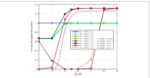
Figure 10 shows the throughput performance of the schemes for varying values of γSRavg when γSDavg = 2 dB and γRDavg = 8 dB. Here, we depict the throughput for
0.7 1 1.5 2 2.5 3 3.5 4
0.5 0.55 0.6 0.65 0.7 0.75 0.8 0.85 0.9 0.95 1
γSDavg [dB]
Average Throughput [bits/symbol]
Di [LDPC,1/2] MH [LDPC,1/2] CD [LDPC,1/2]
SC [LDPC,1/2] − 2/4QAM (num.)
both coding rates of 12 and 25. The throughput of the proposed SC scheme with 4/16-QAM is omitted here as 2/4-QAM achieves a better rate. We can observe that the proposed scheme, whereαˆSC4∗ is found numerically from (75), achieves much the same throughput as the scheme whereαis obtained by exhaustive search in the region of interest (γSRavg ≥ 2.5 dB), proving the validity of our solu-tion. The slight decrease of the analytical throughput SC [LDPC,1/2]-2/4 QAM (ana.) compared to the simulated throughput of the proposed scheme SC [LDPC,1/2]-2/4 QAM (num.) is both due to the assumption in the analysis of only forwarding correctly decoded messages at the relay and to the fact thatαˆ∗SC4is derived from the approximated FER expression.
It is also shown that the proposed method with 2/4-QAM outperforms the conventional relaying methods over most of theγSRavg range forγSDavg = 2 dB andγRDavg =
8 dB, by using a coding rate of 25 for 1 dB ≤ γSRavg ≤
2.8 dB, then the coding rate of 12 over γSRavg ≥ 2.8 dB. Moreover, it greatly enhances the performance of the constant power allocation case SC [LDPC,1/2]-2/4 QAM (const.). Once again, the performance of SC [LDPC,1/2]-2/4 QAM (Gaus.) based on [8] is extremely low, show-ing the necessity of our analysis in the LDPC-coded case, too.
Figure 11 shows the throughput performance of the schemes for varying values of γSRavg when γSDavg = 5 dB andγRDavg = 8 dB and coding rate of 12. In this case, we obtain the numerical solution of (80) αˆ∗SC16 within the range of 0.25 to 0.29, while we obtain the values of the optimal power allocation obtained by exhaustive search from 0.21 to 0.29. Accordingly, we see that the opti-mal throughput SC [LDPC,1/2]-4/16 QAM (exh.) with exhaustive search is closely approached by our scheme with numericalαˆSC16∗ , SC [LDPC,1/2]-4/16 QAM (num.) in the region of interest, namelyγSRavg ≥ 8 dB. Moreover, despite a certain gap due to the same reasons as in the previous case, the analytical throughput SC 4/16 QAM (ana.) is also close to that of SC [LDPC,1/2]-4/16 QAM (num.), showing the validity of the Gaussian approximation for interference. Moreover, the proposed method outperforms the conventional relaying methods forγSRavg ≥8 dB, withγSDavg = 5 dB andγRDavg = 8 dB. The best strategy in Figure 11 is to perform direct transmission for 7 dB ≤ γSRavg ≤ 8 dB, then the proposed SC scheme using 4/16-QAM withαˆSC16∗ , forγSRavg≥8 dB.
Figure 12 shows the throughput performance of the schemes with respect toγSDavg>0.7 dB to meet conditions (55) to (56), whenr = 12,γSRavg = 5 dB andγRDavg = 8 dB. Similar to the uncoded case, the proposed scheme fills well the gap between the conventional relaying schemes and the direct transmission. The proposed SC scheme using half rate LDPC-coded 2/4-QAM withαˆSC4∗ should
be chosen for 0.7 dB< γSDavg ≤2.4 dB, followed by direct transmission forγSDavg>2.4 dB.
Finally, we discuss about the required signaling over-head for implementing the proposed scheme in a practical system. Firstly, node S requires the channel state informa-tion feedback of the SR and SD links in order to optimize the power allocation parameterα∗, as shown in, e.g., (39), while node R requires CSI feedback for the RD link. How-ever, the reference CD scheme of [6] also requires the same amount of CSI feedback as it should adapt its AMC levels depending on the state of the three links. By then, the only additional information that is needed by the proposed scheme is the knowledge of the actual power allocation parameterα which should be sent from S to nodes R and D in step 1. Note that the proposed scheme may still be implemented without this overhead by fixing
α(corresponding to theconst.curves in the figures), but significant gains in throughput are achieved at the expense of some extra bits for control.
7 Conclusions
Considering a three-node wireless relay system with and without FEC, we have proposed an SC-based scheme using discrete HM. We have derived the achievable throughput by analysis, taking into account the decod-ing errors occurrdecod-ing durdecod-ing SIC. Although a closed-form expression of the optimal power allocation parameter could not be derived, we have obtained the necessary conditions of the optimal power allocation, providing the numerical solution used in the proposed scheme. The simulation results show that the proposed scheme closely approaches the throughput performance obtained by exhaustive search for the optimal power allocation, validating our approach. Moreover, it is shown that over a large range of SNRs, the proposed scheme outper-forms the conventional Direct, MH and CD schemes. Thus, relaying based on practical SC is proved to be very effective in a wireless relay system with various discrete modulations and FEC codings.
In the future work, we will extend the proposed SC scheme with discrete HM and coding for serving multiple relayed users in the context of scheduling in cellular relay systems.
Endnotes
aAlthough a total power constraint may be considered for studying the entire system efficiency, setting separate powers reflects the practical system constraints as S and R are distinct entities, each with a given power.
bAlthough there is a certain gap forγavg
SR <18 dB, this
region is not of interest since the best rate is achieved by direct transmission.
Competing interests
Acknowledgements
This work was supported by the Grants-in-Aid for Scientific Research no. 10595739 and no. 24560457 from the Ministry of Education, Science, Sports, and Culture of Japan.
Received: 2 April 2013 Accepted: 11 September 2013 Published: 22 September 2013
References
1. R Pabst, B Walke, DC Schultz, P Herhold, Relay-based deployment concepts for wireless and mobile broadband radio. IEEE Commun. Mag. 42(9), 80–89 (2004)
2. A Sendonaris, E Erkip, B Aazhang, User cooperation diversity part I: system description. IEEE Trans. Commun.51, 1927–1938 (2003)
3. JN Laneman, DNC Tse, GW Wornell, Cooperative diversity in wireless networks: efficient protocols and outage behavior. IEEE Trans. Inform. Theory.50(12), 3062–3080 (2004)
4. T Wang, A Cano, GB Giannakis, JN Laneman, High-performance cooperative demodulation with decode-and-forward relays. IEEE Trans. Commun.55(7), 1427–1438 (2007)
5. Y Zhang, Y Ma, R Tafazolli, Modulation-adaptive cooperation schemes for wireless networks, inProceedings of the IEEE 67th Vehicular Technology Conference (VTC Spring 2008), (Singapore, 11–14 May 2008), pp. 1320–1324 6. K Kimura, M Nakada, T Obara, F Adachi, Single-carrier cooperative DF relay
using adaptive modulation, inProceedings of the 8th IEEE Asia Pacific Wireless Communication Symposium (APWCS 2011), (Singapore, 22–23 August 2011)
7. P Popovski, E de Carvalho, Spectrally-efficient wireless relaying based on superposition coding, inProceedings of the IEEE 65th Vehicular Technology Conference (VTC Spring 2007), (Dublin, 22–25 April 2007), pp. 2936–2940 8. P Popovski, E de Carvalho, Improving the rates in wireless relay systems
through superposition coding. IEEE Trans. Wireless Commun.7(12), 4831–4836 (2008)
9. TM Cover, Broadcast channels. IEEE Trans. Inform. Theory.IT-18, 2–14 (1972)
10. PP Bergmans, TM Cover, Cooperative broadcasting. IEEE Trans. Inform. Theory.IT-20, 317–324 (1974)
11. PK Vittharadevuni, MS Alouini, BER computation of 4/M-QAM hierarchical constellations. IEEE Trans. Broadcasting.47(3), 228–239 (2001) 12. European Broadcasting Union, ETSI EN 300 744, V1.6.1. (2009-01)
European Standard (Telecommunications series), Digital Video Broadcasting (DVB); Framing structure, channel coding and modulation for digital terrestrial television. (2009)
13. H Yamaura, M Kaneko, K Hayashi, H Sakai, Superposition coding scheme with discrete adaptive modulation for wireless relay systems, in Proceedings of the IEEE 74th Vehicular Technology Conference (VTC Fall 2011), (San Francisco, 5–8 September 2011), pp. 1–5
14. J Proakis, M Salehi,Digital Communications, 5th Ed (McGraw-Hill, New-York, NY, 2007), p. 568
15. A Goldsmith,Wireless Communications, 1st Ed (Cambridge University Press, New-York, NY, 2005), p. 262
16. ST Chung, AJ Goldsmith, Degrees of freedom in adaptive modulation: a unified view. IEEE Trans. Commun.49(9), 1561–1571 (2001) 17. MK Simon, MS Alouini,Digital Communication Over Fading Channels:
a Unified Approach to Performance Analysis, 1st Ed (Wiley, Hoboken, New Jersey, 2000), p. 6
18. Q Liu, S Zhou, GB Giannakis, Cross-layer combining of adaptive modulation and coding with truncated ARQ over wireless links. IEEE Trans. Wireless Commun.3(5), 1746–1755 (2004)
doi:10.1186/1687-1499-2013-233
Cite this article as:Yamauraet al.:Adaptive hierarchical modulation and
power allocation for superposition-coded relaying.EURASIP Journal on
Wire-less Communications and Networking20132013:233.
Submit your manuscript to a
journal and benefi t from:
7 Convenient online submission
7 Rigorous peer review
7 Immediate publication on acceptance
7 Open access: articles freely available online
7 High visibility within the fi eld
7 Retaining the copyright to your article