R E S E A R C H
Open Access
Power allocation, bit loading and sub-carrier
bandwidth sizing for OFDM-based cognitive radio
Vinay Thumar
1*, Taskeen Nadkar
1, Tej Gopavajhula
1, Uday B Desai
2and Shabbir N Merchant
1Abstract
The function of the Radio Resource Management module of a Cognitive Radio (CR) system is to evaluate the available resources and assign them to meet the Quality of Service (QoS) objectives of the Secondary User (SU), within some constraints on factors which limit the performance of the Primary User (PU). While interference mitigation to the PU spectral band from the SU’s transmission has received a lot of attention in recent literature; the novelty of our work is in considering a more realistic and effective approach of dividing the PU into sub-bands, and ensuring that the interference to each of them is below a specified threshold. With this objective, and within a power budget, we execute the tasks of power allocation, bit loading and sizing the sub-carrier bandwidth for an orthogonal frequency division multiplexing (OFDM)-based SU. After extensively analyzing the solution form of the optimization problems posed for the resource allocation, we suggest iterative algorithms to meet the
aforementioned objectives. The algorithm for sub-carrier bandwidth sizing is novel, and not previously presented in literature. A multiple SU scenario is also considered, which entails assigning sub-carriers to the users, besides the resource allocation. Simulation results are provided, for both single and multi-user cases, which indicate the effectiveness of the proposed algorithms in a CR environment.
Keywords:cognitive radio, OFDM, interference mitigation, power allocation, bit loading, sub-carrier bandwidth sizing
I. Introduction
A new paradigm, called Cognitive Radio (CR), has emerged in the field of wireless communication, to alle-viate the imbalance between spectrum allocation and its use [1,2]. CR entails the temporary usage of unused por-tions of the spectrum (spectrum holes or white spaces), owned by the licensed users (Primary Users–PUs), to be
accessed by unlicensed users (Secondary Users–SUs).
Built on the platform ofsoftware-defined radio (SDR), a
CR node is renderedreconfigurable: the SDR allows the
operating parameters such as frequency range, modula-tion type or output power to be reconfigured in soft-ware, without making any alteration in the hardware [2].
It is anticipated that theNext-Generation(xG)
commu-nication networks will be based on CR [2]. These net-works will provide high bandwidth to mobile users via heterogenous wireless architectures and dynamic
spec-trum access techniques. Besides the tasks of spectrum
sensing, spectrum allocation, spectrum sharing and
spectrum mobility, one of the key functions of CR nodes
in spectrum-aware xG networks isspectrum utilization.
The spectrum utilization function entails efficient Radio Resource Management (RRM), the aim of which is to evaluate the available resources (power, time slots, band-width, etc) and assign them to meet the QoS objectives of the SU, within some constraints on factors (typically interference) which limit the performance of the PU [3]. Furthermore, for optimum spectrum utilization it is necessary to be adaptive to, one or more, time-varying characteristics of the system, such as the wireless chan-nel state, number of users, QoS requirements, etc.
OFDM is a widely-deployed multi-carrier modulation technology for various wireless application segments, besides being a popular choice for CR. Other than its ability to handle multi-path fading and inter-symbol interference, it offers flexibility of resource allocation (power, constellation size and bandwidth) of its indivi-dual sub-carriers. The two main impairments in OFDM are inter-symbol interference (ISI) and inter-carrier
* Correspondence: [email protected] 1Indian Institute of Technology, Bombay, 400076, India
Full list of author information is available at the end of the article
interference (ICI) [4]. ISI is mitigated by the addition of a guard interval (GI) which should be longer than that delay spread of the channel (also known as the cyclic prefix, since it is a cyclic copy of the original symbol). The loss of orthogonality between the sub-carriers of OFDM due to its sensitivity to frequency offsets results in ICI. Frequency errors which occur due to local oscil-lator errors can be easily compensated by frequency tracking, while those due to Doppler spread are poorly compensated for.
In conventional OFDM systems, optimum power allo-cation that maximizes the channel capacity under a total power budget is water-filling [4]. However, when OFDM is used for the SU system in a CR scenario, it’s side-lobes causes interference to the PUs, limiting their
per-formance. The Federal Communications Commission’s
(FCC) Spectrum Policy Task Force has recommended a metric called the interference temperature which when exceeded causes harmful interference to the PU band. The issue of interference mitigation in the PU band is receiving increasing attention in recent literature [5-14]. In an OFDM-based SU system, the amount of
interfer-ence to the PU band depends on the SU’s sub-carrier
parameters (power and bandwidth), the spectral distance between the SU’s sub-carriers and the PU band, as well as the channel between the SU and PU. Bit loading (or constellation sizing or modulation) for CR imposes an additional condition that a given performance should be achieved in every sub-carrier. The SNR gap is used to measure the reduction of SNR (signal to noise ratio) with respect to the capacity; it depends on the target error probability required in every sub-carrier when it carries log2(M ) bits per symbol, either QAM (quadra-ture amplitude modulation) or PSK (phase shift keying) modulated [15]. The sub-carrier bandwidth selection in OFDM is a trade-off between increasing the sub-carrier bandwidth to decrease the ICI, and reducing the band-width to mitigate ISI [16,22]. In CR, the interference to the PU band is a function of the SU sub-carrier band-width; the optimum sub-carrier bandwidth is, therefore, the one that maximizes the SU throughput while miti-gating the PU interference.
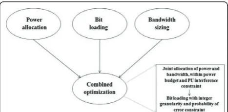
The contribution of this paper is in developing a hol-istic resource allocation scheme for an OFDM-based CR, which includes power allocation, bit loading and sub-carrier bandwidth sizing. First, we address each of these issues as independent problems; the objective
being - maximization of the SU’s throughput under a
power budget and an interference constraint for the PU spectral band. Then, a joint optimization problem is for-mulated, which encompasses the aforementioned indivi-dual problems (Figure 1). In each case, we consider a realistic and efficient strategy, wherein the PU is divided into bands, and the interference to each of its
sub-bands is separately constrained. In case of both single and multi-user scenarios, the optimization problems are difficult to solve due to either non-linearity of equations or their combinatorial nature. A rigorous examination of their solution form motivates the development of computationally simple, sub-optimum algorithms for the problems posed. The proposed strategies for power allo-cation and bit loading outperform those which have been previously presented in literature; while those for adaptive sub-carrier sizing for CR, are novel and have not been proposed earlier. (We would like to note here that the titles of some works of literature on CR suggest adaptive sub-carrier bandwidth/allocation[11,23,24], which actually refers to the assignment of sub-carriers
to users in a multiple SU scenario, and notsub-carrier
bandwidth sizing.)
To detail the proposed scheme, the paper has been organized as follows: Section 30 presents related litera-ture. Section 31 describes the system model and com-munication scenario for a single SU. Sections 33, 35, VI and VII describe the power allocation, bit loading, sub-carrier bandwidth sizing and combined optimization problems, respectively. Likewise, SectionsVIII-XII are dedicated to the corresponding multiple SU situation. It is followed by a complexity analysis of each of the pro-posed algorithms, in Section XIII. Section XIV presents exhaustive simulation results and their discussion, while Section XV concludes the paper.
II. Related work A. Power allocation
Weiss et al. [5] have characterized the mutual interfer-ence between the PU and SU in an OFDM-based CR. Bansal et al. [6] have formulated the power allocation problem for a single SU with the objective of maximiz-ing it’s throughput while maintaining the interference to the entire PU band below a threshold, however, without a total power constraint. The model of Wang et al. [7] considers a single SU and multiple PUs; the system bandwidth is divided into sub-channels, and different PUs co-exist with the SU on each sub-channel. A
loss model is used between the SU and PU to determine the peak power constraint of each sub-channel. Addi-tionally, a total power constraint is included and the
objective is to maximize the SU’s capacity. The
algo-rithm used is called iterative partitioned water-filling. The system model of Wang et al. [8] is similar to that of [7], however, they have additionally considered the side-lobe power in each SU sub-channel, contributed by the neighboring sub-carriers, in the optimization problem.
The situation for multiple SUs is more challenging, since it involves allotment of sub-carriers to users, besides power allocation, under the specified constraints. Münz et al. [25] and Jang et al. [26] have suggested stra-tegies for multi-user power allocation with the objective of maximizing the total data rate. Shen et al. [27] have proposed power allocation with proportional fairness among the users. Wong et al. [23] and Kivanc et al. [24] have provided bit-loading and power allocation algo-rithms to minimize the total transmit power in the multi-user scenario.
Power allocation for multiple SUs in the CR scenario has also received considerable attention in recent litera-ture. Chengshi et al. [9] have performed multi-user water-filling for CR. More recently, Shaat et al. [10] and Bansal et al. [11], have presented a Lagrangian formula-tion for maximizing the sum capacity of multiple SUs subject to a power budget and PU interference con-straints. Since the combinatorial optimization problem is computationally complex, both references have pro-posed sub-optimal schemes. First the users are allocated SU sub-carriers based on the best channel conditions, and the interference constrained maximum power limit
on each SU sub-carrier is computed; then acap-limited
water-filling is executed [10]. On the other hand, the users are allocated sub-carriers based on the channel-to-noise ratio (CNR), and the Lagrangian formulation is used to maximize the sum capacity of the SUs under the PU interference constraints [11].
B. Bit loading
Two main classes of bit loading problems are: rate
max-imization (RM)–maximizing the data rate within a
power budget; and margin maximization (MM)–
mini-mizing power consumption given a target data rate [28]. The implementation of bit loading algorithms in litera-ture fall into two broad categories. The first category of algorithms use numerical methods that employ Lagran-gian optimization, resulting in real numbers for the bit loading ([23,29,30]). However, for practical constellation sizing, the number of bits allocated per sub-carrier is restricted to integer values, which imposes a combina-torial structure in the loading optimization problem. The second category of algorithms employ a discrete
greedy method in order to obtain optimum integer bit allocation results ([31-38]). Bit loading for a multi-user OFDM scenario has been addressed by Wong et al. [23] and Huang et al. [39] for MM and RM problems, respectively.
In the CR context, the following work exists in litera-ture: Tang et al. [12] have formulated a bit loading pro-blem for multiple SUs, which is based on maximizing total system throughput under interference power con-straint to PUs, individual data rate concon-straints for the SUs and total transmission power constraint. Cheng et al. [13] have used a game-theoretic approach to formu-late a transmit power control game for CR, which jointly solves the bandwidth allocation, bit loading and power allocation problems. Budiarjo et al. [14] have used the Fischer and Huber algorithm [37] for bit-loading for a single SU, followed by Raised Cosine windowing to miti-gate the side lobe interference to the PU.
C. Sub-carrier bandwidth sizing
The most significant literature on sub-carrier bandwidth sizing is summarized in this section. Das et al. [16,17] have proposed an approach for adaptive bandwidth for sub-carriers for single user OFDM and a multi-user sce-nario [18]. Zhang and Ma [19] have also proposed the implementation of variable sub-carrier bandwidth for a multi-user OFDM down-link scenario. Steendam and Moeneclaey [20], Harvatin and Ziemer [21], and Tufves-son and Maseng [22] have demonstrated the impact of varying the sub-carrier bandwidth on the system perfor-mance in a time and frequency-selective channel (either in terms of interference power or in terms of BER), but do not discuss the gains from dynamically adjusting the bandwidth.
optimization and computational complexity. Similar considerations are applied for PU interference mitigation in the proposed bit loading and sub-carrier bandwidth sizing algorithms.
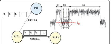
III. System Model and Communication Scenario: Single SU
In the current model, a single SU transceiver is consid-ered, and a PU exists in its radio range (Figure 2). OFDM is the communication technology of the SU, the use of which divides the available bandwidth into fre-quency-flat sub-carriers. When the PU claims a portion of the spectrum, the SU nulls the corresponding sub-carriers. Let Ns be the number of active sub-carriers for the SU. The transmission opportunity is detected by the SU in the spectrum sensing phase of its cognitive cycle
[1]. The channel power gain of the ith sub-carrier on
the link between the SU transmitter (Tx) and receiver (Rx) is denoted byhi. To efficiently control the
interfer-ence to the PU, the PU spectrum is divided into Np
sub-bands of equal width, and the gain of the jth
sub-band from the SU Tx to the PU Rx is given bygj. In the present work, we have considered an immobile SU, resulting in no Doppler spread. It is assumed that the frequency offset due to any other source is compensated [40], and consequently we ignore the effect of ICI. The mutual interference model between the PU and SU is assumed [5].
Resource allocation strategies in CR require that the channel state information (CSI) be known to the SU Tx. It is assumed that the SU Rx estimates the channel by measuring the received power of the pilot signals sent by the transmitter, and the CSI is fed back to the trans-mitter [41]. A robust and low-complexity protocol can be used for the feedback. A block fading propagation channel is assumed where the channel remains constant during the resource allocation and transmission process. The channel sensing and feedback is done once per coherence time. Estimating the channel between the PU Tx and SU Rx, as well as that between the SU Tx and PU Rx, is more challenging, and entails the use of blind estimation techniques [41].
The maximum achievable throughput of the SU, in bits/sec, is given by [16]
C= 1
in whichBis the sub-carrier bandwidth,Tgis the dura-tion of the guard interval, andPiis the power allocated to theith SU sub-carrier.σi2=σ2+Ji, wheres2
is the Addi-tive White Gaussian Noise (AWGN) variance, andJiis the
interference from the PU on the ith SU subcarrier. Ji
depends on the power spectral density (PSD) of the PU and the channel gain between the PU Tx and SU Rx.
The interference from the SU on thejth PU sub-band
is formulated as after adding the guard interval,Tsis the length of the sym-bol without the guard interval, andfirepresents the center frequency of theith subcarrier. Sinc(x) is the mathematical function commonly defined by Sin(πx)/(πx).
IV. Power allocation
In the power allocation problem, our objective is to maximize the SU throughput under a total node power constraint Pt, in such a way that the interference to the
jth PU sub-band is less than a thresholdIthj.Ijth=TthjBWj,
whereTthj is the interference temperature limit for thejth PU sub-band and BWjis its bandwidth. For simplicity of representation, we assume that the interference thresh-old is the same for all PU sub-bands and is denoted by Ith. The optimization problem can stated as
Problem P1
The Lagrangian for the above is formulated as
L(Pi,λj,μ,βi) =
−μ sion forC, is a constant in the power optimization pro-blem, and is ignored in the above expression and all the subsequent analysis in this section. lj,μ andbi are the Lagrangian multipliers. The problem is a convex optimi-zation problem, and Karush-Kuhn-Tucker (KKT) condi-tions [42] are applied to find the optimum solution. Also, since we requirePi≥0,bi is substituted as 0, due to the complementary slackness condition [42]. The optimum power allocation is given by [43] (which refers to our own previous work)
Pi∗= max
Though the above solution looks like water-filling, it is different from the conventional water-filling technique in the fact that each SU sub-carrier has a different water level. We would like to note here that the problem formula-tion in [7] and [8] appear similar to the above problem (P1). However, the system model of the current work and that of the aforementioned references are significantly dif-ferent–while the former considers the system bandwidth to be frequency division multiplexed by the PU and SU, the latter assumes the two entities to be spatially separate but occupying the same spectrum. In the problem formu-lation of [7], the inequality constraints are decoupled, making the problem simpler to solve using either an
exhaustive search-based approach or aniterative
parti-tioned water-filling. On the other hand, in the formulation of [8], the inequality constraints are coupled by the use of dependent variables. Its solution involves segregating the equality (binding) and inequality (non-binding) constraints for the given power budget using a search-based approach and computing the optimal solution from the equality constraints. This technique has a high computationally complexity. The proposed method attempts to find a low-complexity sub-optimum solution after a detailed analysis of the solution form.
As the optimization problem (P1) is convex with lin-ear constraints, at the optimum point some constraints are binding, while the others are non-binding. If the power budget of the SU (Pt) is too small, then that will
be a binding constraint and all interference constraints are non-binding; the corresponding Lagrange multipliers (lj) are zero and the solution looks like that of conven-tional water-filling with a constant water level:
Pi∗=max(1
If the power budget is very high, then only the inter-ference constraint will be binding. Generally, thejthPU sub-carrier which receives the maximum interference will be responsible for the binding constraint; and the solution looks like
To make it a general water-filling solution with a con-stant water-level, we can multiply bygjQj, i, to get
and the power allocation is
Pi∗= ϑi
Qj,igj (15)
If we consider the above solution as the peak power on each SU sub-carrier i.e.Pmax
i , under the PU
interfer-ence constraint (as in [10]), and then execute water-fill-ing, it is referred to as cap-limited water-filling. The solution takes the form
Pi∗= min(max
If the power budget is neither too high nor too low, the solution will take the form given by (9). On substi-tutingPi∗in the constraint of (4), we get
The solution to the above Np equations cannot be
obtained directly, and we propose an iterative algorithm (Algorithm 1) to achieve the objective ofP1, given the interference constraints on each PU sub-band and the power budget.
Algorithm 1
1)Initialize allljandμ.
2)Compute Piby substituting the aboveljandμin (9).
Compute the total power allocated as Ps=∑Pi
3) For each PU sub-band calculate the difference between the interference generated and the threshold, as diffj = Ij-Ith. Calculate the difference between the total
power allocated and the power budget, as diffp= Ps-Pt. 4)For each PU sub-carrier, If(diffj> 0)
lj=lj+ aj* diffj
end If If(diffp> 0)
μ=μ+ b * diffp
end If
5)If (diffj> 0) or (diffp> 0)
Goto Step2. Else
End Algorithm end If
In the first step of the algorithm, we initialize all lj andμ, such that the resultant power allocation violates one or all of the constraints. In the subsequent steps, we
update the Lagrange multipliers ljandμ in proportion
to diffjand diffprespectively.ajandb are the step sizes;
aj= diffj/max(diffj) andb = 1/Ns. The process is itera-tively repeated until all the constraints are satisfied.
V. Bit loading
The power allocation and bit-loading problems are closely related. However, in this section we treat bit-loading as an independent problem, and address the issue of practical constellation sizing with integer number of bits per sym-bol, under a power budget and PU interference constraint for an OFDM-based CR. The number of bits that can be transmitted on theithOFDM sub-carrier is given by [44]
bi= log2
1 + Pihi
σ2
i
(18)
where Γ is the SNR gap calculated according to the
gap approximationformula [44,15], based on the target
probability of error (Pe). M-ary QAM (M-QAM) is a
preferred choice of modulation, because it is more energy efficient than M-ary PSK (M-PSK) while retain-ing the same bandwidth-efficiency. When rectangular M-QAM is deployed (biÎ2, 4, 6, ...), we can write [45]
≥ 1
3
Q−1(Pe/4)2 (19)
whereQ -1is the inverse of the well-known Q
func-tion given by
Q= √1
2
∞
x
e−t2/2dt (20)
For non-rectangular QAM signal constellations (bi
Î 3, 5, 7, ...), the SNR gap is given by (19) without
the equality [45]. In the case of BPSK, the SNR gap is approximated by [Q-1(Pe/4)]
2
/2, which is slightly larger than the right hand side of (19). However, for simplicity and practicality, (19) with the equality
sign is used to approximate the SNR gap for bi Î
ℤ+ [45].
The optimization problem for bit-loading can stated as
Problem P2
obj= max
bi Ns
i=1
bi (21)
subject to
gj Ns
i=1
(2bi−1) αi
Qj,i≤Ith ∀j (22)
Ns
i=1
2bi−1
αi ≤
Pt (23)
bi∈Z+ (24)
where αi= σhi2
i. (22) and (23) represent the
interfer-ence and power budget constraints respectively. The constraint of (24) represents the integer constraint for practical constellation sizing. It turns out that the above
problem (P2) is a combinatorial optimization problem
[28]; to make it tractable, the integer constraint is relaxed to
bi≥0 (25)
and the following substitution is made
2bi−1
αi
=Pi (26)
The problem is now equivalent to the single user power allocation problem (P1), and the solution to it is characterized the way it has been done in Section IV. We propose a few iterative algorithms, with varying degrees of trade-off between optimality of solution and computational complexity.
The first of the proposed bit loading algorithms com-prises two steps; to start with, the power allocationPiis
computed usingAlgorithm 1, and the corresponding
executed till both the constraints are met. The complete algorithm operates as follows:
Algorithm 2
1)Compute the transmit power Pi using Algorithm 1,
and the corresponding bit-load bi using (18)
2) bi = ceil(bi), where ceil() represents rounding to the
nearest higher integer.
3) Calculate the transmit power Picorresponding to
the quantized biusing (25), and the interference caused
to each PU sub-band, Ij, using (2).
Compute the total power allocated as Ps=∑Pi
4)If{(Ps> Pt) OR (Ij> Ith(for any j))}
{
While{Ij> Ith∀j}Do {
Compute the power saved in removing one bit from the ithSU subcarrier as Pi=α1
i2
bi−1.
Compute the reduced interference in the jthPU
sub-band due to removal of one bit from every ith SU
sub-carrier as ΔIj, i=gjΔPiQj, i, which is a vector of
size Np×Ns.
Compute the maximum element of the vector ΔIj, i,
max{ΔIj, i}, and remove a bit from the sub-carrier
identified by the corresponding column index i. Update the bit allocation profile bi and the
corre-sponding power allocation profile Pi. }
While{Ps> Pt}Do {
Compute the power saved in removing one bit from the ithSU subcarrier as Pi=α1
i2
bi−1.
Remove one bit from the sub-carrier that corresponds to the highestΔPi.
Update the bit allocation profile bi, and the
corre-sponding power allocation profile Pi.
Compute the total power allocated as Ps=∑Pi. }
} end If.
Motivated by the need to reduce the computational
complexity associated with Algorithm 2 (due to the
iterative power allocation process ofAlgorithm 1 in its Step 1), we also propose a simple greedy bit allocation process with two passes. In the first pass bit-loading is executed till the power constraint is met; and in the second pass, bit-removal is performed till the interfer-ence constraint is satisfied. The algorithm is as follows:
Algorithm 3
1) Initialize the bits allocated to each sub-carrier bi to
zero.
Compute the corresponding power allocation Piusing
(25), and the total power allocation as Ps=∑Pi.
2)While{Ps< Pt}Do
{
Compute the power required to add one bit to the ith SU subcarrier as Pi= α1i2bi.
Add one bit to the sub-carrier that corresponds to the lowestΔPi.
Update the bit allocation profile bi and the
corre-sponding power allocation profile Pi.
Compute the total power allocated as Ps=∑Pi. }
3) Compute the interference caused to each PU
sub-band, Ij, using (2).
4)While{Ij> Ith ∀j}Do
{
Compute the power saved in removing one bit from the ithSU subcarrier as Pi=α1i2bi−1.
Compute the reduced interference in the jthPU
sub-band due to removal of one bit from every ith SU
sub-carrier asΔIj, i=gjΔPiQj, i, which is a vector of
size Np×Ns.
Compute the maximum element of the vectorΔIj, i,
max{ΔIj, i}, and remove a bit from the sub-carrier
identified by the corresponding column index i. Update the bit allocation profile bi, the corresponding
power allocation profile Pi, and the interference
caused to each PU sub-band, Ij }
The execution of two passes can be further condensed to a single loop, which executes till both the power and interference constraints are met. This is rendered possi-ble inAlgorithm 4, by the introduction of a new metric, viz, power weighted by the spectral distance from the PU band.
Algorithm 4
1) Initialize the bits allocated to each sub-carrier bi to
zero.
Compute the corresponding power allocation Pi, and
the total power allocation as Ps=∑Pi.
2)While{(Ps< Pt) AND (Ij< Ith∀j)}Do
{
Compute the metric ΔWPi=ΔPi/di, which represents
the power saved in removing one bit from the ithSU subcarrier weighted by the distance of the ith sub-carrier from the PU band.
Add one bit to the sub-carrier that corresponds to the lowestΔWPi.
Update the bit allocation profile bi, the corresponding
power allocation profile Pi, and the interference
caused to each PU sub-band, Ij
Compute the total power allocated as Ps=∑Pi. }
The proposed algorithms have been compared on the basis of their computational complexity and perfor-mance in Section XIII and XIV, respectively. Intuitively,
we can expectAlgorithm 2to give the best performance,
since its solution is obtained from the optimization problem. But it is associated with high complexity. Algorithm 3 entails bit-removal till the PU interference constraint is met without any compensatory bit-addition in some other sub-carrier to improve the throughput. Consequently its performance will be inferior to
Algorithm 2. Algorithm 4, though computational the
simplest, will result in poorer performance as compared to the previous two algorithms because of weightingΔPi with di, which may not always give the desired result. For instance, ifΔPiis very small anddiis small, it may result in an overall low value of the metric causing a bit to be added on that sub-carrier at the cost of increased PU interference.
VI. Sub-carrier bandwidth sizing
The OFDM sub-carrier bandwidth should be greater than the Doppler spread of the channel and less than the coherence bandwidth. An increase in the bandwidth results is a corresponding increase in the throughput (1) unto a certain point, after which the throughput falls due to a drop in the bandwidth efficiency. In a CR sce-nario, the sub-carrier bandwidth also impacts the PU interference. Increasing the bandwidth implies decreas-ing the number of sub-carriers, and thereby, the node power is distributed among lesser sub-carriers; a higher power in each sub-carrier generates higher side-lobe interference in the PU band. Consequently, as the band-width increases, the interference to the PU band increases, within a fixed power budget. This has been observed during simulation study and the results are plotted in Sect. XIV.
In the optimum sub-carrier bandwidth sizing problem for an OFDM-based CR, the objective is to maximize
the SU throughput under a power budget and PU interference constraint. It can be posed as follows:
Problem P3
obj= max
B C (27)
subject to
Ij≤Ith ∀j (28)
Ns
i=1
Pi≤Pt (29)
0≤B≤ fc (30)
The first two constraints are the same as those of Equations 4 and 5, but are repeated for completeness.
Δfc is the coherence bandwidth of the channel. Since
presently mobility is not considered, the bandwidth is lower bounded by 0 (in the case of mobile SUs, the
bandwidthBshould be greater than the Doppler spread
of the channel). To solve the above problem for the
optimum bandwidthB*, the sub-carrier power is
consid-ered to be uniform, i.e.Pi=Pt/Ns. However, it is possi-ble that none of the values of bandwidth satisfy the PU interference constraint within the given power budget, and consequently the solution to the above problem does not exist. Only if the power budget is very small, some value of bandwidth may satisfy the interference constraint. Therefore, both the sub-carrier bandwidth and power need to be varied to arrive at an optimum OFDM configuration which meets the interference con-straint, within the power budget, while maximizing the achievable throughput. The problem entails solving for B*andP∗i, and can be posed as
Problem P4
obj= max
B,Pi C (31)
subject to the same constraints as those of problem P3, and additionally
Pi≥0 (32)
Here the number of SU sub-carriers is a function of the bandwidthB, as follows:
Ns= 2∗BW
B −1 (33)
where BW is the total system bandwidth.
The objective function (31) is concave since its Hessian is positive semi-definite [42], and the problem
(polynomial in B) constraints. It has been analyzed to form a convex optimization problem (though the proof has not been included). Its Lagrangian will look like
L(B,Pi,κj,χ,ω,ψi) =
1
Tg+ 1B
Ns
i=1
log2
1 + Pihi
σ2
i
−(34)
Np
j=1
κj(Ij−Ith)−χ
N
s
i=1
Pi−Pt
−ω(B− fc) +
Ns
i=1
ψiPi (35)
wherej,c,ω andψiare the Lagrangian multipliers. Applying KKT conditions to solve the problem results in complex non-linear equations (as discussed in Appendix A), which cannot be solved directly. A graphical, as well as intuitive analysis of the variation of sub-carrier bandwidth (in discrete steps of Ns) with corresponding power allocation uniformly (Pi =Pt/Ns), by water-filling, and by Algorithm 1, reveals its relation with the achievable throughput. Unto a certain point, an increase in bandwidth results in a corresponding increase in throughput; after which, any further increase results in the symbol duration becoming relatively smal-ler than the guard interval, and the bandwidth efficiency reduces. The proposed iterative algorithm is motivated by this discussion; it is a search-based approach, in which, initially the throughput is computed in larger
steps of Ns, with the power allocation at every point
obtained fromAlgorithm 1(which ensures the PU
inter-ference constraint being met within the power budget). Then a finer search is executed to look for the global
optima. Ns (number of sub-carriers) is the preferred
choice of variable, as compared to B, due to its integer granularity. The two are related as given by (33). The algorithm is as follows:
Algorithm 5
1) Initialize the sub-carrier bandwidth to its maximum value, i.e. B =Δfc.
2)Calculate the corresponding number of sub carriers
asNsmin, using (33).
3) Initialize Cprev(Pi)=Cnew(Pi)=0 (where C(Pi)
represents the achievable throughput obtained from (1)).
Initialize the number of sub-carriers Ns=Nsmin
While{Cprev(Pi)<=Cnew(Pi)}Do {
Cprev(Pi)=Cnew(Pi)
Increment the number of sub-carriers with some suitable step-size s, i.e. Ns= Ns+s.
Find the power allocation Piusing Algorithm 1.
Calculate throughput Cnew(Pi)using (1). }
4)Ns= Ns-s.
Calculate the throughput for the number of sub-carriers Ns, Ns+1, Ns-1 and represent them CNs(Pi),
CNs+1(Pi), CNs-1(Pi), respectively, using Algorithm 1
and (1).
5) While {(CNs(Pi) < (CNs+1(Pi)) OR (CNs(Pi) <CNs-1 (Pi))}Do
{
s = ceil(s/2)
If{CNs(Pi) <CNs+1(Pi)}
Ns= Ns+s.
end If
If{CNs(Pi) <CNs-1(Pi)}
Ns= Ns-s.
end If
Calculate throughput for the number of sub-carriers Ns, Ns+1, Ns-1 and represent them as CNs(Pi), CNs+1 (Pi), CNs-1(Pi), respectively, using Algorithm 1 and (1). }
6) Nsopt = Ns, and the corresponding sub-carrier
bandwidth Bopt is obtained using (33).
VII. Sub-carrier power allocation, bandwidth sizing and bit loading
After having addressed the power allocation, bit loading and bandwidth sizing individually, we formulate the problem of doing all the three together, for an OFDM-based CR, with the objective of maximizing the SU throughput. It is as follows:
Problem P5
obj= ma
B,Pi xC (36)
subject to the PU interference constraint (4), power budget (23), the integer bit granularity (24), and bounds on the sub-carrier bandwidth (30).
The proposed algorithm first computes the power allocation and sub-carrier bandwidth using the strategy discussed in the previous section. The corresponding bit load are real values, which are rounded to the nearest higher integer, and a greedy bit removal is executed till the power and PU interference constraint are met.
Algorithm 6
1) Compute the optimum power allocation Pi and
sub-carrier bandwidth B using Algorithm 5.
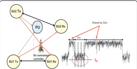
VIII. System Model and Communication Scenario: Multiple SUs
In this scenario, we assume that there are K SU
transceivers, and the PU is in the radio range of all of them (Figure 3). The assumptions on the propagation channel are the same as in the single user case (Sect. III). The multi-user scenario is more complex than the single user situation, since it involves assigning sub-car-riers to users, besides allocating power under the given constraints. The throughput of thekth user on theith sub-carrier is defined as
ck,i(pk,i) =log2
wherepk, i is the power allocated to theith sub carrier assigned to thekth user, andhk, iis channel power gain ofkth user onith sub carrier.
The Ns active SU sub-carriers will be assigned to
the various users, while optimizing the sum through-put under a power budget and an interference con-straint on each PU sub-band. The sum throughput is given by
All the CSI estimated at the receivers, is now required to be sent to a centralized controller, which is responsi-ble for coordinating the resource allocation in the multi-user CR network. A centralized mode involves considerable signaling overheads, especially in fast fading environments. In a slow fading environment as is assumed in this work, the centralized architecture will compensate for the overheads with near-optimum solutions.
Note: To avoid complexity of notations, we have used the same variables (for the Lagrangian multipliers) for the single and multi-user cases. Their values will, however, depend on the specific problem.
IX. Power allocation (Multiple SUs)
To formulate the power allocation problem for the multi-user CR scenario, (38) is re-written as
Cm= 1
1 if theithsub carrier is allocated tokthuser;
0 if theithsub carrier is not allocated tokthuser. (40)
Our objective is to maximize the sum throughput,
given the total power budget on all users Pt, and the
interference constraint on each PU sub-band. The pro-blem is posed as
Problem P6
wheregk, j is the channel power gain betweenkth SU andjthprimary band.
K
The Lagrangian for the above is formulated as
L(ζk,i,ρk,i,λj,μ,γi,βk,i) =C−
On applying KKT conditions to solve the convex optimization problem, we get (details in Appendix XV)
ζ∗
in which
Hk,i(λj,μ) =log(
hk,i
(Npj=1λjgk,jQj,i+μ)σ2)− (50)
(1− (
Np
j=1λjgk,jQj,i+μ)σ2
hk,i
) (51)
From the above analysis, we infer that there are two main steps in solving the multi-user power allocation problem within the power budget and the PU interfer-ence constraint. In the first step, we allocate sub-carriers to the users. This can be done by assigning
sub-carrier i to that user k that will maximize the
function Hk, i, i.e.
ρk,i∗ =
1Hk,i>Hk,i∀k;
0otherwise. (52)
Next, we compute the power on each SU sub-carrier using (48). This looks like a water-filling solution with different water levels, as in the case of a single user. But it can be inferred from (48)-(51), that for multiple SUs, the sub-carrier assignment and power allocation are not independent of each other and the solution to the equa-tions cannot be obtained directly.Hk, i is proportional to the ratio of the channel gain of the kthuser on the ith sub-carrier to the cumulative interference of all theNp PU bands, weighted by the corresponding Lagrangian multiplierslj. Hk, iwill be used as the metric to assign sub-carriers to users in the proposed power allocation
algorithm (Algorithm 7). The proposed algorithm is
devised to iteratively assign sub-carriers and allocate the powers till neither the interference or power constraints are violated.
Algorithm 7
1)Initialize allljandμ.
2)Initializeljoldandμoldto zero.
3)Assign each sub-carrier i to that user k that will maximize the function Hk, i.
4)Compute ξk, i by substituting the above lj and μ
in (48).
Compute the total power allocated as Ps=∑k∑iζk, i
Calculate the interference caused to each PU sub-band, Ij(from left hand side of (42)).
5) For each PU sub-band calculate the difference
between the interference generated and the threshold, as diffj = Ij-Ith. Calculate the difference between the
total power allocated and the power budget, as diffp=
Ps-Pt.
6)ljold=lj∀jandμold=μ
If(max(diffj) < 0) and (diffp< 0)
lj= (ljold+lj)/2∀j
μ= (μold+μ)/2
Goto Step3. end If
7)For each PU sub-carrier, If(diffj> 0)
lj=lj+ aj* diffj
end If If(diffp> 0)
μ=μ+ b * diffp
end If
8)If (diffj> 0) or (diffp> 0)
Goto Step3. Else
End Algorithm end If
The step sizesajandb are the same as those defined inAlgorithm 1.
X. Bit loading (Multiple SUs)
The objective of the bit loading problem is the same as the corresponding single user case, i.e.Problem P2, addi-tionally requiring the sub-carriers to be assigned to the
Kusers. The problem is posed as
Problem P7
obj=max
K
k=1 Ns
i=1
εk,i (53)
whereεk, i =bk, i*rk, i(rk, iis described in (40))
K
k=1 Ns
i=1
gk,j(2
εk,i−1) αk,i
Qj,i≤Ith ∀j (54)
wheregk, j is the channel power gain betweenkth SU andjthPU band.
K
k=1 Ns
i=1
(2εk,i−1)
αk,i ≤
Pt (55)
whereαk,i= σhk2i
i
K
k=1
ρk,i= 1 ∀i (56)
We relax the integer constraint to
εk,i≥0 (58)
and make the following substitution
(2εk,i−1) αk,i
=ζk,i (59)
The problem becomes equivalent to the multi-user power allocation problem (P6). Similar to the single user bit-loading, we propose iterative algorithms to arrive at the optimum integer bit allocation for practical
constel-lation sizing. The first such algorithm (Algorithm 8)
computes the power allocation usingAlgorithm 7 and
rounds the corresponding bit load to the nearest higher integer. Then a greedy bit-removal is executed till both the power and interference constraints are met.
Algorithm 8
1)Compute the transmit power,ζk’, i, using Algorithm 7.
Compute the corresponding bit-loadεk’, iusing (59).
The subscript k’indicates the optimum user assign-ment on the ith subcarrier usingrk, i.
2)εk’, i= ceil(εk’, i), where ceil() represents rounding to
the nearest higher integer.
3)Calculate the transmit power,ζk’, i, corresponding to
the quantized bk’, i using (59), and the interference
caused to each PU sub-band, Ij, using the left hand side
of (42).
Compute the total power allocated as Ps=∑iζk’, i
4)If{(Ps> Pt) OR (Ij> Ith)}
{
While{Ij> Ith∀j}Do {
Compute the power saved in removing one bit from the ith SU subcarrier as ζk,i=
1 αk,i2
εk,i−1, where
αk,i= σhk2,i
iCompute the reduced interference in the j th
PU sub-band due to removal of one bit from every ith SU sub-carrier as ΔIj, i=gk’, jΔζk’, iQj, i, which is a
vector of size Np×Ns.
Compute the maximum element of the vector ΔIj, i,
max{ΔIj, i}, and remove a bit from the sub-carrier
identified by the corresponding column index i. Update the bit allocation profile, εk’, iand the
corre-sponding power allocation profile,ζk’, i. }
While{Ps> Pt}Do {
Compute the power saved in removing one bit from the ithSU subcarrier as ζk,i= α1
k,i2 εk,i−1
.
Remove one bit from the sub-carrier that corresponds to the highestΔζk’, i.
Update the bit allocation profile,εk’, iand the
corre-sponding power allocation profile,ζk’, i.
Compute the total power allocated as Ps=∑iζk’, i. }
} end If.
The next algorithm (Algorithm 9), on the other hand, involves a greedy bit allocation which reduces the computational complexity. In its first pass, bit-loading is executed till the power constraint is met; and in the sec-ond pass, bit-removal is performed till the interference constraint is satisfied. The algorithm is as follows:
Algorithm 9
1)Compute the metric h(k, i)/∑jg(k, j), which is a vector
of size K×Ns.
2)Identify the maximum element of each column, and
corresponding row index k’ denotes the assignment of that user to the ithsub-carrier.
3) Initialize the bits allocated to each ithsub-carrier, bk’, ito zero.
Compute the corresponding power allocation pk’, i,
and the total power allocation as Ps=∑ipk’, i.
4)While{Ps< Pt}Do
{
Compute the power required to add one bit to the ith SU subcarrier as pk,i= α1
k,i2 b
k,i.
Add one bit to the sub-carrier that corresponds to the lowestΔpk’, i.
Update the bit allocation profile, bk’, iand the
corre-sponding power allocation profile, pk’, i.
Compute the total power allocated as Ps=∑ipk’, i. }
5) Compute the interference caused to each PU
sub-band, Ij, using left hand side of (42). 6)While{Ij> Ith∀j}Do
{
Compute the power saved in removing one bit from the ithSU subcarrier as pk,i=α1
k,i2 bk,i−1
.
Compute the reduced interference in the jth PU
sub-band due to removal of one bit from every ith SU sub-carrier as asΔIj, i=gk’, jΔpk’, iQj, i, which is a
Compute the maximum element of the vector ΔIj, i,
max{ΔIj, i}, and remove a bit from the sub-carrier
identified by the corresponding column index i. Update the bit allocation profile, bk’, i, the
corre-sponding power allocation profile, pk’, i, and the
inter-ference caused to each PU sub-band, Ij }
The execution of the two passes can be further con-densed to a single loop, which executes till both the
power and interference constraints are met. Algorithm
10achieves that by using the power weighted by the dis-tance from the PU band, as its metric.
Algorithm 10
1)Compute the metric h(k, i)/∑jg(k, j), which is a vector
of size K×Ns.
2)Identify the maximum element of each column, and
corresponding row index k’denotes the assignment of that user to the ithsub-carrier.
3) Initialize the bits allocated to each ithsub-carrier, bk’, ito zero.
Compute the corresponding power allocation pk’, i,
and the total power allocation as Ps=∑ipk’, i.
Compute the interference caused to each PU sub-band, Ij, using the right hand side of (42).
4)While{(Ps< Pt) AND (Ij< Ith)}Do
{
Compute the metric ΔW Pk’, i = Δpk’, i/di, which
represents the power spent in adding one bit to the ithSU subcarrier weighted by the distance of the ith sub-carrier from the PU band.
Add one bit to the sub-carrier that corresponds to the lowestΔW Pk’, i.
Update the bit allocation profile, bk’, i, the
corre-sponding power allocation profile, pk’, i, and the
inter-ference caused to each PU sub-band, Ij
Compute the total power allocated as Ps=∑ipk’, i. }
XI. Sub-carrier bandwidth sizing (Multiple SUs)
The sub-carrier bandwidth sizing problem for multiple SUs entails computing the assignment of sub-carriers to the users, and the optimum power and bandwidth that will maximize the sum throughput, subject to a net power budget and PU interference constraint. The pro-blem is formulated as
Problem P8
The Lagrangian for the above is formulated as
L(ζk,i,ρk,i,κj,χ,γi,ω,ψk,i) =Cm−
The non-linearity of the equations associated with the problem solution (as explained for the corresponding single user case in Appendix XV), coupled with the task of assigning sub-carriers to the multiple users, make the problem extremely complex. To make the problem tractable, a search-based algorithm is executed, in dis-crete steps ofNs, to identify that the value of the sub-carrier bandwidth, which will maximize the net through-put of the SUs, within the power budget, while mitigat-ing the PU interference. The algorithm is as follows:
Algorithm 11
1) Initialize the sub-carrier bandwidth to its maximum value, i.e. B =Δfc.
2)Calculate the corresponding number of sub carriers
asNsminusing 33.
3)InitializeCmprev(pk,i) =Cmnew(pk,i) = 0(where Cm(pk, i)
Initialize the number of sub-carriers Ns=Nsmin
While{Cmprev(pk,i)<=Cmnew(pk,i)}Do {Cmprev(pk,i) =Cmnew(pk,i)
Increment the number of sub-carriers with a suitable step-size s, i.e. Ns= Ns+s.
Find the assignment of sub-carriers to users and the power allocation using Algorithm 7.
Calculate throughputCmnew(pk,i)using (38). }
4)Ns= Ns-s.
Calculate the throughput for the number of sub-car-riers Ns, Ns+1, Ns-1 and represent them asCmNs(pk,i), CmNs−1(pk,i),CmNs−1(pk,i), respectively, using Algorithm
7 and (38).
5)While{(CNs(pk, i) <CNs+1(pk, i)) OR (CNs(pk, i) <CNs-1 (pk, i))}Do
{
s = ceil(s/2)
If{CNs(pk, i) <CNs+1(pk, i)}
Ns= Ns+s.
end If
If{CNs(pk, i) <CNs-1(pk, i)}
Ns= Ns-s.
end If
Calculate throughput for the number of sub-carriers Ns, Ns+1, Ns-1 and represent them as CmNs(pk,i), CmNs−1(pk,i),CmNs−1(pk,i), respectively, using Algorithm
7 and (39). }
6)Nsopt= Ns, and the corresponding sub-carrier
band-width Bopt is obtained using (33).
XII. Sub-carrier power allocation, bandwidth sizing and bit loading (Multiple SUs)
The joint problem of power allocation, bit loading and bandwidth sizing for the multiple SU scenario, is posed as follows:
obj=max Cm (69)
subject to the PU interference constraint (42), power budget (55), the integer bit granularity (57), bounds on the sub-carrier bandwidth (30), and the integer variable for assigning sub-carriers to users (44).
The iterative algorithm which is meant to solve for optimum power allocation, bit load and sub-carrier bandwidth, operates as follows:
Algorithm 12
1) Compute the optimum power allocation pk, i and
sub-carrier bandwidth B using Algorithm 11.
2)Compute the corresponding bit load bk, iusing (59),
andεk, i= bk, i*rk, i.
3)Execute Step 2 onwards of Algorithm 8.
XIII. Complexity Analysis
In this section, we analyze the worst-case computational complexity of each of the proposed algorithms.
A. Single User Algorithms
The computational complexity of single-user
water-fill-ing for conventional OFDM isO(Nlog N), whereNis
the number of sub-carriers that are sorted in the order of their channel gain-to noise ratio [28]. The proposed power allocation algorithm for a single SU in the CR
scenario (Algorithm 1) is an iterative process which
starts from some initial values of the Lagrangian
multi-pliers μ and lj, and converges when both the PU
interference constraint and power budget are satisfied. Let C1 andC2 represent the initial total power (∑Pi) and initial maximum interference among all the PU sub-bands (maxIj), respectively. Then, since each iteration
entails Np× Ns computations, the complexity of this
algorithm is given by
O(max(C1−Pt,C2−Ith)NpNs) (70)
The first of the proposed bit loading algorithms for CR (Algorithm 2) obtains non-real values of the bit allocation using Lagrangian multiplier optimization, followed by rounding to the nearest higher integer and then a greedy bit removal till both the PU interference constraint and power budget are satisfied. Each greedy
bit-removal from Ns SU sub-carriers involvesNp ×Ns
computations. Thus, the computational complexity is given by
O(|max(C1−Pt,C2−Ith)NpNs|+|NpNs2|) (71)
The complexity of greedy bit-addition and bit-removal
for conventional OFDM are given as O(BtarN) andO
((Bmax - Btar)N), respectively. In the proposed greedy
bit-addition algorithm for CR (Algorithm 3), we start
with an all zeros allocation and add bits till the power budget is met. This involves log(Pt×CNR) iterations, where CNR represents the maximum channel-to-noise ratio among all the SU sub-carriers. Then, the algorithm executes a greedy bit-removal till the PU interference
constraint is met. The complexity of Algorithm 3 is
given by
O(|log(Pt×CNR)Ns|+|log(Ith
As compared to Algorithm 3, Algorithm 4 has condensed the two passes into a single pass which exe-cutes till both the constraints are satisfied. Its complexity is given by
O(min(log(Pt×CNR),log(Ith×CNR))×NpNs) (73)
Out of the three proposed bit loading algorithms, Algorithm 2 has the highest computational complexity.
This is followed by Algorithm 4 and Algorithm 3 in
that order. It can be attributed to the following facts: Algorithm 2 involves calculation Piusing Algorithm 1, and hence the overall number of iterations are very high. Algorithm 3initially entails a conventional greedy bit-addition pass which has complexity O(Ns) in each iteration, and is followed by a greedy bit-removal pass with a complexity O(NpNs) in each iteration. The sec-ond pass will involve very few iterations, unless the
power budget is very high. On the other hand, in
Algo-rithm 4, each essential iteration requires a complexity O(NpNs).
The sub-carrier bandwidth sizing algorithm (Algorithm 5) involves two passes: in the first pass a crude search is
conducted with a relatively larger step size of Ns,
followed by a fine search to look for the global optima. The computational complexity of the complete algorithm is therefore given by
O(|X|+|Y|) (74)
in which X and Yrepresent the complexities of the
crude search and fine search respectively.
The algorithm involves computing the power allocation for eachNs usingAlgorithm 1. If we denote Nsmax−Nsmin
s asSN, then
X= max(C1−Pt,C2−Ith)×Np×(Nsmin+ (Nsmin+s)(75)
+(Nsmin+ 2s) +. . .(Nsmin+SNs)) (76)
which can be simplified as
X=max(C1−Pt,C2−Ith)NpSNNsmax (77)
The fine search involves computing the power alloca-tion three times corresponding to Ns, Ns+ 1 andNs- 1 in each iteration. Thus, we get
Y=max(C1−Pt,C2−Ith)×Np×(Nsmax+ (Nsmax+
s
2)+ (78)
(Nsmax+
s
2+
s
4) + (Nsmax+
s
2+
s
4+
s
8) +· · · ·(Nsmax+· · · ·+
s
2logs)) (79)
which can be simplified as
Y=max(C1−Pt,C2−Ith)×Np×logs×(Nsmax+ (
s
2)
logs) (80)
Algorithm 6 uses Algorithm 5 for power allocation
and bandwidth sizing, which is followed by greedy
bit-removal usingAlgorithm 2. Thus, its computational
complexity is given by
O(|X|+|Y|+|NpN2sopt|) (81)
whereNsoptrepresents the number of sub-carriers cor-responding to the optimum bandwidth.
B. Multiple User Algorithms
The multi-user power allocation algorithm (Algorithm 7) entails assigning sub-carriers to the KSUs, besides the power allocation. Hence, its complexity is given by
O(min(C−Pt,C−Ith)K NpNs) (82)
The complexity of the bit allocation algorithm (Algorithm 8) is given by
O(|max(C1−Pt,C2−Ith)K NpNs|+|NpN2s|) (83)
The complexity ofAlgorithm 9andAlgorithm 10 will
be the same as the corresponding single-user algorithms (Algorithm 3 andAlgorithm 4). As such, their complex-ities are given by (72) and (73), respectively. This is because, in these two algorithms assigning sub-carriers to users is not an iterative process, rather is computed once at the beginning of the algorithms.
Sub-carrier bandwidth sizing for multiple SUs (Algorithm 11) also involves assigning sub-carriers to the
KSUs, and its complexity is given by (referring to the
corresponding single-user algorithm complexity in (74))
O(|K X|+|K Y|) (84)
The complexity ofAlgorithm 12, which involves power
allocation, bandwidth sizing and bit loading for multiple SUs is given by (referring to the corresponding single-user algorithm complexity in (81))
O(|K X|+|K Y|+|NpN2sopt|) (85)
XIV. Simulation Results and Discussion A. Single user
Power Allocation
For the single user case, we assume that the total system bandwidth for the PU and SU is 6 MHz wide, of which the SU occupies a contiguous band of 5 MHz, while the PU occupies 1 MHz bandwidth. The SU transceiver uses 32 sub-carrier OFDM for communication. The channels undergo Rayleigh multi-path fading, defined in
the time domain by L−1
l=0
hlδ(t−lT)where hlis the
taps. The lth channel coefficient is distributed as N(0,
s2
), and the frequency domain channel is given by its Fourier Transform. The AWGN variance is assumed to
be s2 = 1e-4 and the guard interval length isTg = 1
μsec. The PU band is divided into 8 sub-bands, and we
attempt to mitigate the interference to each of them.
We set the interference temperature,Tth= 1e-5 W/Hz
for each PU sub-band. Without loss of generality, it is assumed that the interference induced by the PU to the SU is negligible.
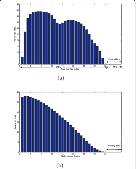
The power allocation profile of the SU is shown in Figure 4. For the result of Figure 4a, the power budget Pt= 100 mW. This value being very small, the interfer-ence constraint is non-binding, and it is observed (though the channel gains have not been plotted) that the solution closely resembles that of conventional water-filling: better channels are allocated higher powers as compared to the poorer ones. As the power budget is increased to 1 W (Figure 4b), the interference constraint becomes binding. The graph tapers towards the PU band because lesser power is allocated in the SU sub-carriers spectrally closer to the PU.
The SU throughput versus power budget is plotted in Figure 5. Conventional water-filling gives the highest SU throughput, since it is unconstrained by the PU interference threshold. It is closely followed by uniform
power allocation. The cap-limitedscheme [10] is only
partially interference constrained by the closest PU sub-band. On the other hand, the proposed scheme (Algorithm 1) considers the interference threshold to each PU sub-band. The SU throughput achieved is the optimum result within the given power budget and interference constraints. It is observed that when the power budget is very low, the solution is very close to that of conventional water-filling since only the power constraint is binding. Furthermore, after a certain
power budget (Pt= 700 mW), the throughput hardly
increases, since only the interference constraint is binding. Any further increase in the power budget, cannot increase the SU sub-carrier power allocation without violating the interference constraint. These results have been averaged over 100 independent reali-zations of the channel.
We have also provided the interference profile to the 8 PU sub-bands on execution of the various power allo-cation schemes (Figure 6). The proposed algorithm maintains the interference to each PU sub-band under
the threshold. The cap-limitedscheme is successful in
keeping only the interference to the closest PU sub-band under the threshold. We have also included for comparison, the power allocation scheme which consid-ers the entire PU as a single band for mitigating
0 4 8 12 16 20 24 28 32
0 1.0 1.5 2.0 2.5 3.0 3.5 4.0 4.5 5.0
Subícarrier Index
Power in mW
Primary Band
5 MHz 1 MHz
(a)
0 4 8 12 16 20 24 28 32
0 10 20 30 40 50 60
Subícarrier Index
Power in mW
Primary Band
(b)
Figure 4Power profile:(a)Pt= 100 mW;(b)Pt= 1 W.
0.1 0.2 0.3 0.4 0.5 0.6 0.7 0.8 0.9 1.0 1.5
2 2.5 3 3.5 4 4.5 5 5.5 6
Primary power budget ( Pt ) in Watts
Throughput in Bits/sec/Hz
Proposed scheme (Algo 1) Waterfillingíbased allocation Uniform allocation Capílimited scheme
Figure 5Secondary user throughput versus power budget.
1 2 3 4 5 6 7 8
0 0.2 0.4 0.6 0.8 1 1.2 1.4x 10
í4
Primary subíband Index
Interference power in watts/Hz
Proposed scheme ( Algo 1 ) Capílimited scheme Waterfilling based allocation Uniform allocation Considering single PU band
Ith
interference, as is done in literature [6]. It can be observed that it is not as effective as dividing the PU
into sub-bands, as is proposed in Algorithm 1. These
results are reported for a power budgetPt= 1 W, and a single instance of the channel.
The proposed power allocation algorithm is verified for five different positions of the PU within the given system bandwidth of 6 MHz, and a power budget of 1 W in each case. As observed in Figure 7, each profile tapers towards the PU band.
Bit loading
The simulation parameters for bit loading are the same as those assumed for power allocation. The SNR gap is computed considering an error probabilityPe= 10-6.
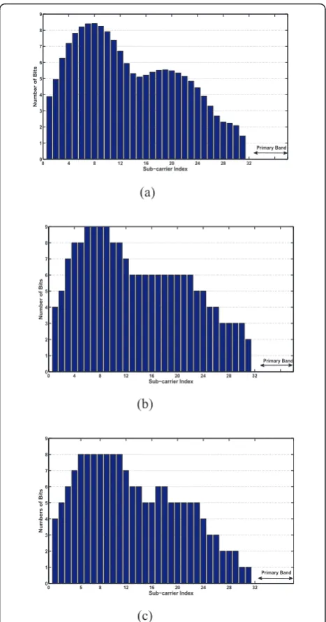
The result of Algorithm 2is depicted in Figure 8. Fig-ure 8a demonstrates the results of executing the Lagran-gian optimization problem, which yields real numbers for the bit allocation. This is followed by integer quanti-zation to the nearest higher integer (Figure 8b), causing the interference to the PU to increase beyond the speci-fied threshold (Ith), or the power constraint (Pt) to be violated. A greedy bit-removal is executed, resulting in the final allocation of bits (Figure 8c). It can be observed that the interference constraint causes the profile to
taper towards the PU band. A power budget Ptof 1 W
is considered for these graphs.
The bit allocation profile achieved with the proposed algorithms, i.e.Algorithm 2, Algorithm 3andAlgorithm
4 are shown together in Figure 9; while those obtained
with the schemes proposed in literature are depicted in
Figure 10. A power budget Ptof 1 W is considered in
each of these cases. Though much cannot be concluded from Figure 9, the SU throughput for various algo-rithms, averaged over 100 independent realizations of the channel (Figure 11), reveals more about their
Figure 7Power profile for different positions of the primary user.
0 4 8 12 16 20 24 28 32
0 1 2 3 4 5 6 7 8 9
Subícarrier Index
Number of Bits
Primary Band
(a)
0 4 8 12 16 20 24 28 32
0 1 2 3 4 5 6 7 8 9
Subícarrier Index
Number of Bits
Primary Band
(b)
0 5 8 12 16 20 24 28 32
0 1 2 3 4 5 6 7 8 9
Subícarrier Index
Numbers of Bits
Primary Band
(c)
Figure 8 Bit profile for Algorithm 2: (a) After Lagrangian; (b) rounding; (c) bit removal.
0 4 8 12 16 20 24 28 32
0 1 2 3 4 5 6 7 8
Subícarrier Index
Number of Bits
Proposed scheme ( Algo 2 ) Proposed scheme ( Algo 3 ) Proposed Scheme ( Algo 4 )
Primary Band
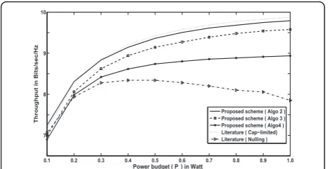
performance: the highest throughput is achieved by the cap-limited scheme proposed in literature [10], since it only mitigates interference to the closest PU band. It is followed closely by that obtained from the proposed Algorithm 2.Algorithm 3and Algorithm 4follow, in that order. The scheme from literature which is based on sub-carrier nulling [14] gives the lowest throughput.
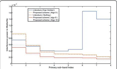
The interference profile to the 8 PU sub-bands on execution of the aforementioned bit allocation schemes is depicted in Figure 12. While the proposed algorithms, Algorithm 2-4, are successful in mitigating the interfer-ence to each of the PU sub-bands, the cap-limited scheme only does so for the spectrally closest PU sub-band. The subcarrier-nulling scheme, however, generates the lowest interference profile, since it nulls sub-carriers till interference to each band is mitigated.
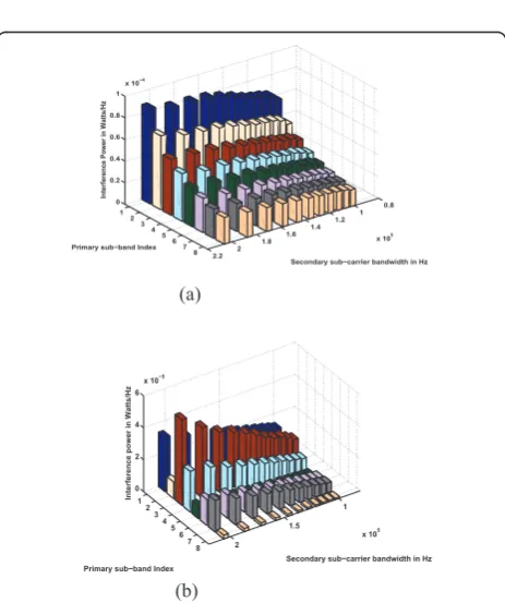
Sub-carrier bandwidth sizing
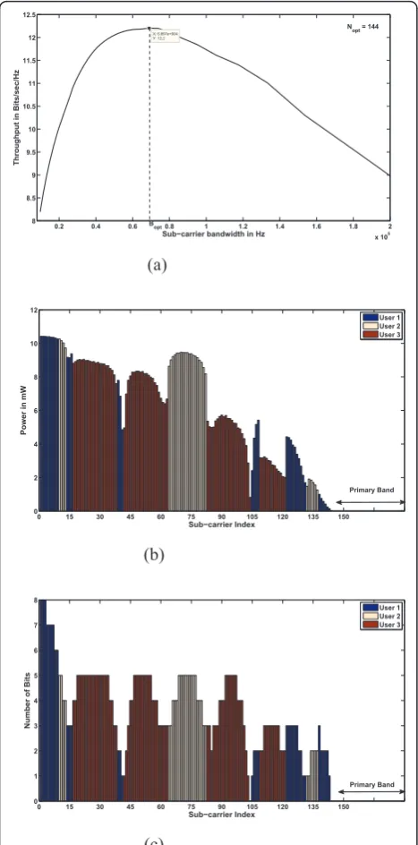
The simulation parameters are the same as those described for the power allocation and bit loading pro-blems. However, the 5 MHz SU bandwidth is not divided into 32 sub-carriers anymore. Instead, the pro-blem entails searching for that sub-carrier bandwidth which will maximize the SU throughput, while mitigat-ing the interference to the PU band. The coherence bandwidth isΔfc = 200 KHz (Δfc= 1 = 5sτ[46], where
sτis the rms delay spread, and assumed to be 1μsec).
The power budget at the SU Tx isPt= 1 W.
In Figure 13, we analyze the SU throughput, while increasing the sub-carrier bandwidth unto the
coher-ence bandwidth Δfc. Although not plotted, it is
expected that the SNR will increase with an increase in the sub-carrier bandwidth, however, the same cannot be said about the throughput. It is observed (Figure 13) that unto a certain point, an increase in bandwidth results in a corresponding increase in throughput; after which, any further increase results in the symbol dura-tion becoming relatively smaller than the guard inter-val, and the throughput reduces. Initially, a crude
search was conducted by varying Ns in a step size of
10 as indicated by the markers in Figure 13. Then a fine search was conducted to look for the global
optima. The execution of Algorthm 5 yielded Nsoptas
101 and the corresponding Bopt as 99.01 Khz. The
optimum SU sub-carrier bandwidth should also main-tain the interference to the PU band below the speci-fied threshold. To understand the effect of varying sub-carrier bandwidth on the PU interference, we have plotted Figures 14 and 15 by dividing the PU band into 4 and 8 sub-bands, respectively, and allocating the power uniformly. In both cases, the following 0 4 8 12 16 20 24 28 32
0 1 2 3 4 5 6 7 8
Subícarrier Index
Number of Bits
Literature ( Capílimited ) Literature ( Nulling )
Primary Band
Figure 10Bit profile (literature).
0.1 0.2 0.3 0.4 0.5 0.6 0.7 0.8 0.9 1.0 7
8 9 10
Power budget ( Pt ) in Watt
Throughput in Bits/sec/Hz
Proposed scheme ( Algo 2 ) Proposed scheme ( Algo 3 ) Proposed scheme ( Algo4 ) Literature ( Capílimited) Literature ( Nulling )
Figure 11Secondary user throughput versus power budget (all bit loading schemes).
1 2 3 4 5 6 7 8
0 0.5 1 1.5 2 2.5 3 3.5 4
4.5x 10
í5
Primary subíband Index
Interference Power in Watts/Hz
Literature ( Capílimited ) Proposed scheme ( Algo 4 ) Proposed sheme ( Algo 2 ) Literature ( Nulling ) Proposed scheme ( Algo 3 )
Ith
Figure 12Primary user interference profile (all bit loading schemes).
0 0.2 0.4 0.6 0.8 1 1.2 1.4 1.6 1.8 2
x 105
3 4 5 6 7 8 9
X: 9.901e+004 Y: 8.732
Subícarrier Bandwidth in Hz
Throughput in Bits/sec/Hz
Nopt = 101
Bopt
Figure 13 Secondary user throughput vs. sub-carrier