Release 4.3
Update
Comcode 108158080
Issue 1
Copyright 1997, Lucent Technologies All Rights Reserved
Printed in U.S.A. Notice
Every effort was made to ensure that the information in this book was com-plete and accurate at the time of printing. However, information is subject to change.
Your Responsibility for Your System’s Security
Toll fraud is the unauthorized use of your telecommunications system by an unauthorized party, for example, persons other than your company’s employees, agents, subcontractors, or persons working on your company’s behalf. Note that there may be a risk of toll fraud associated with your tele-communications system and, if toll fraud occurs, it can result in substantial additional charges for your telecommunications services.
You and your system manager are responsible for the security of your sys-tem, such as programming and configuring your equipment to prevent unauthorized use. The system manager is also responsible for reading all installation, instruction, and system administration documents provided with this product in order to fully understand the features that can introduce risk of toll fraud and the steps that can be taken to reduce that risk. Lucent Technologies does not warrant that this product is immune from or will pre-vent unauthorized use of common-carrier telecommunication services or facilities accessed through or connected to it. Lucent Technologies will not be responsible for any charges that result from such unauthorized use.
Lucent Corporate Security
Whether or not immediate support is required, all toll fraud incidents involving Lucent products or services shoud be reported to Lucent Corpo-rate Security at 1 800 821-8235. In addition to recording the incident, Lucent Corporate Security is available for consultation on security issues, investigation support, referral to law enforcement agencies, and educational programs.
Lucent Technologies Fraud Intervention
If you suspect that you are being victimized by toll fraud and you need tech-nical support or assistance, call the Lucent Technologies National Customer Care Center Toll Fraud Intervention Hotline at 1 800 643-2353.
Federal Communications Commission Statement
Part 15: Class A Statement. This equipment has been tested and found to
comply with the limits for a Class A digital device, pursuant to Part 15 of the FCC Rules. These limits are designed to provide reasonable protection against harmful interference when the equipment is operated in a commer-cial environment. This equipment generates, uses, and can radiate radio-fre-quency energy and, if not installed and used in accordance with the instruction manual, may cause harmful interference to radio communica-tions. Operation of this equipment in a residential area is likely to cause harmful interference in which case the user will be required to correct the interference at his own expense.
Part 68: Network Registration Number. This equipment is registered
with the FCC in accordance with Part 68 of the FCC Rules. It is identified by an FCC registration number.
Part 68: Answer-Supervision Signaling. Allowing this equipment to be
operated in a manner that does not provide proper answer-supervision sig-naling is in violation of Part 68 Rules. This equipment returns answer-supervision signals to the public switched network when:
• Answered by the called station • Answered by the attendant
• Routed to a recorded announcement that can be administered by the CPE user
This equipment returns answer-supervision signals on all DID calls for-warded back to the public switched telephone network. Permissible excep-tions are:
• A call is unanswered • A busy tone is received • A reorder tone is received
Canadian Department of Communications (DOC) Interference Information
This digital apparatus does not exceed the Class A limits for radio noise emissions set out in the radio interference regulations of the Canadian Department of Communications.
Le Présent Appareil Nomérique n’émet pas de bruits radioélectriques dépassant les limites applicables aux appareils numériques de la class A préscrites dans le reglement sur le brouillage radioélectrique édicté par le ministére des Communications du Canada.
Trademarks
See the section titled “About This Book.”
Ordering Information
Call: Lucent Technologies Publications Center
Voice 1 800 457-1235 International Voice 317 361-5353 Fax 1 800 457-1764 International Fax 317 361-5355
Write: Lucent Technologies Publications Center P.O. Box 4100
Crawfordsville, IN 47933
Order: Comcode 108158080 Issue 1, October 1997
You can be placed on a standing order list for this and other documents you may need. Standing order will enable you to automatically receive updated versions of individual documents or document sets, billed to account infor-mation that you provide. For more inforinfor-mation on standing orders, or to be put on a list to receive future issues of this document, contact the Lucent Technologies Publications Center.
Warranty
Lucent Technologies provides a limited warranty on this product. Refer to the “Limited Use Software License Agreement” card provided with your package.
European Union Declaration of Conformity
Lucent Technologies Business Communications Systems declares that the equipment specified in this document conforms to the referenced European Union (EU) Directives and Harmonized Standards listed below:
EMC Directive 89/336/EEC Low-Voltage Directive 73/23/EEC
The “CE” mark affixed to the equipment means that it conforms to the above directives.
Comments
To comment on this document, return the comment card at the front of the document.
Acknowledgment
About This Document
iii■ Overview iii
■ Purpose iii
■ Intended Audiences iv
■ Release History iv
■ How to Use This Update iv
■ Safety and Security Alert Labels v
■ Trademarks and Service Marks v
■ Related Resources vii
Documentation vii
Technical Assistance vii
1
Update for MAP/5P System Installation
1-1■ Overview 1-1
■ Purpose 1-1
■ Setting Frequencies and Frequency
Groups for Call Progress Tones 1-2
Example 1-7
Special Considerations for Dial Tone Training 1-7
■ Setting Parameters for Basic Call Progress Tones 1-8
Examples 1-12
■ Setting Additional Call Progress Tones 1-12 ■ Determining Call Progress Tones 1-16
Examples 1-19
2
Update for MAP/40P System Installation
2-1■ Overview 2-1
■ Purpose 2-1
■ Tone Customization Update 2-2
Contents
3
Update for MAP/100 System Installation
3-1■ Overview 3-1
■ Purpose 3-1
■ Tone Customization Update 3-2
■ Frequency Specification Update 3-2
4
Update for Integration with MERLIN LEGEND
Communications System
4-1■ Overview 4-1
■ Purpose 4-1
■ Disconnect Tone Is Not Recognized 4-2
Tone Capture and Analysis 4-2
Frequency Specification 4-10
Tone Specification 4-14
First Additional Tone Screen 4-18
■ Dial Tone Is Not Detected 4-21
■ Outcalling Functions Do Not Work 4-22
■ Calls Are Not Transferred 4-22
Overview
This chapter describes:
■ Intended audiences ■ Release history
■ How to use this update
■ Safety and security alert labels ■ Trademarks and service marks ■ Related resources
Purpose
About This Document
Intended Audiences
This document is intended primarily as an update for the on-site technical personnel who are responsible for installing the Lucent INTUITY system or for integrating the system with a MERLIN LEGEND® switch. Secondary audiences include the following from Lucent Technologies:
■ Field support ■ Helpline personnel ■ Sales support ■ Design support ■ Factory ALT personnel
■ Provisioning project managers
We assume that the primary users of this book have completed the Lucent INTUITY hardware installation training course.
Release History
This is the first release of this update.
How to Use This Update
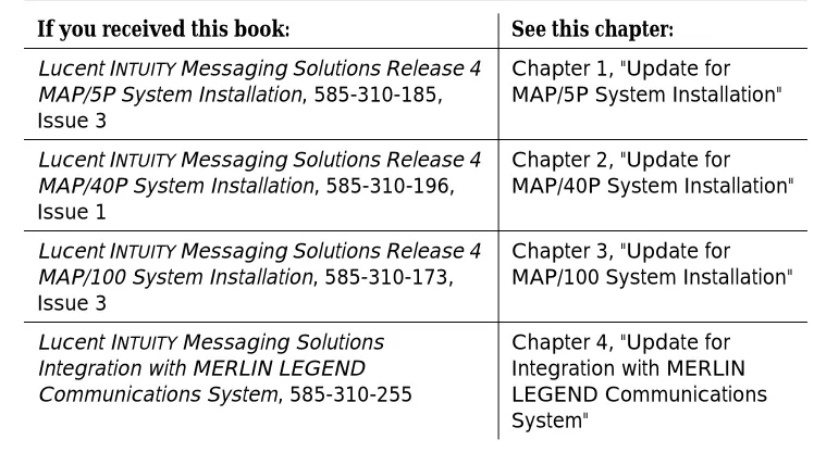
If you have received any of the following books, see Table 1 for the corresponding chapters in this update:
Table 1. Books Impacted by This Update
If you received this book: See this chapter:
Lucent INTUITY Messaging Solutions Release 4
MAP/5P System Installation, 585-310-185, Issue 3
Chapter 1, "Update for MAP/5P System Installation"
Lucent INTUITY Messaging Solutions Release 4
MAP/40P System Installation, 585-310-196, Issue 1
Chapter 2, "Update for MAP/40P System Installation"
Lucent INTUITY Messaging Solutions Release 4
MAP/100 System Installation, 585-310-173, Issue 3
Chapter 3, "Update for MAP/100 System Installation"
Lucent INTUITY Messaging Solutions
Integration with MERLIN LEGEND Communications System, 585-310-255
Safety and Security Alert Labels
This update uses the following symbols to call your attention to potential problems that could cause personal injury, damage to equipment, loss of data, or service interruptions:
!
CAUTION:
Indicates the presence of a hazard that if not avoided can or will cause minor personal injury or property damage, including loss of data.
!
WARNING:
Indicates the presence of a hazard that if not avoided can cause death or severe personal injury.
!
DANGER:
Indicates the presence of a hazard that if not avoided will cause death or severe personal injury.
Trademarks and Service Marks
The following trademarked products are mentioned in this update:
■ AUDIX is a registered trademark of Lucent Technologies. ■ DEFINITY is a registered trademark of Lucent Technologies. ■ DMS-100 is a trademark of Northern Telecom Limited. ■ Dterm is a trademark of NEC Telephones, Inc.
■ INTUITY is a trademark of Lucent Technologies.
■ Lucent is a trademark of Lucent Technologies.
■ MERLIN LEGEND is a registered trademark of Lucent Technologies. ■ Microsoft is a registered trademark of Microsoft Corporation.
■ MS is a registered trademark of Microsoft Corporation. ■ MS-DOS is a registered trademark of Microsoft Corporation. ■ Mitel is a trademark of Mitel Corporation.
■ NEAX is a trademark of NEC Telephone, Inc.
■ NEC is a registered trademark of NEC Telephones, Inc.
About This Document
■ Rolm is a registered trademark of International Business Machines. ■ SX-100 is a trademark of Mitel Corporation.
■ SX-200 is a trademark of Mitel Corporation. ■ SX-2000 is a trademark of Mitel Corporation.
Related Resources
This section describes additional documentation and technical assistance available for you to learn more about the installation of your Lucent INTUITY system.
Documentation
NOTE:
See the appropriate book for specific information on planning, installing, administering, or maintaining a Lucent INTUITY system. See the Lucent INTUITY online catalog for more information on other books in the set.
Use the following books in conjunction with this update:
■ Lucent INTUITY Messaging Solutions Release 4 installation book specific to your platform for a detailed source of complete installation procedures and troubleshooting information
■ Lucent INTUITY Messaging Solutions Release 4 maintenance book specific to your platform for a detailed source of complete maintenance
procedures and troubleshooting information
■ Lucent INTUITY Messaging Solutions Integration with MERLIN LEGEND Communications System, 585-310-255, for more detailed instructions for integrating the MERLIN LEGEND with the Lucent INTUITY system
See the inside front cover for information on how to order Lucent INTUITY documentation.
Technical Assistance
The following numbers are available for technical assistance with Lucent Technologies products and services:
■ Within the United States
— For systems integrated with a MERLIN LEGEND switch, call 1-800-628-2888.
— For systems integrated with any other switch, call 1-800-242-2121 x85474.
■ Within Canada
— For all systems, call 1-800-242-1234.
■ Within any other country
1
Update for MAP/5P System
Installation
Overview
This chapter is an update to Appendix C, “Troubleshooting Procedures”, in Lucent INTUITY™ Messaging Solutions Release 4 MAP/5P System Installation, 585-310-185.
Purpose
The purpose of this chapter is to provide updated troubleshooting procedures for switch integration.
!
CAUTION:
Before you begin these troubleshooting procedures, you must have already completed all relevant procedures in Chapter 6, "Initial Administration for Switch Integration". See your switch administrator to verify the correct settings for your switch, if necessary, before beginning these
troubleshooting procedures.
You may need to complete the following procedures if:
■ Outcalling functions, including fax outcalling, do not work ■ Disconnect tone is not recognized
Due to the frequency limitations of the Lucent INTUITY system, there may be some problems in detecting the far-end disconnect in some countries. Additional administration may be required on the switch to ensure that the far-end disconnect is recognized.
By default, most switches use U.S. parameter settings for different switch tones in all countries. Therefore, all dial tone, busy tone detection, and reorder tones are based on U.S. settings. These tones do not create any problems in the internal call answer function. Problems arise in countries where the disconnect (usually busy) tone is provided by the network.
Therefore, when the voice is being coded or recorded from an external call and the external caller disconnects the call, the Lucent INTUITY system might not be able to do call progress tone detection or to detect the disconnect tone. In this case, the disconnect tone is recorded with the message until Lucent INTUITY finally times out.
NOTE:
This problem does not occur if the public switch network gives a polarity disconnect or wink disconnect. The polarity disconnect or wink disconnect option needs to be ordered from the central office, if possible.
Setting Frequencies and Frequency
Groups for Call Progress Tones
Use this procedure to set the country-specific and switch-specific frequencies and frequency groups that the Lucent INTUITY system uses to recognize call progress tones that the switch sends.
Each call progress tone is made up of one or two frequencies. Accordingly, a frequency group is either a single frequency or a set of two frequencies that you define as a group so the group can then be assigned to a particular type of tone.
The frequencies and frequency groups set on this window are also displayed on the following windows used to set the parameters for call progress tones. See "Setting Parameters for Basic Call Progress Tones" and "Setting Additional Call Progress Tones".
■ Windows for basic call progress tones:
— Dial Tone window
— Busy Tone window
— Reorder Tone window
— Ring Tone window
Setting Frequencies and Frequency Groups for Call Progress Tones
■ Windows for custom-specified call progress tones
— First Additional Tone window
— Second Additional Tone window
— Third Additional Tone window
The required frequencies may differ for the five types of call progress tones, though in general each country (or switch) uses a small number of frequencies to define all tones. In some cases a single frequency is used for all tones.
NOTE:
Besides frequency, call progress tones are also distinguished by cadence, that is the number and duration of ON/OFF cycles that compose the tone. The cadence is set on the various tone windows. See "Setting Parameters for Basic Call Progress Tones" and below.
For ease of administration of the call progress tones, you can assign as many as three distinct frequency groups that contain appropriate sets of frequencies (one, two, or three frequencies) to cover all the types of tones your system uses.
This procedure also allows you to enable dial tone training. In dial tone training, the system analyzes the dial tone that the switch sends to determine its
constituent frequencies. If the frequencies obtained from the analysis differ from the frequencies set in your Lucent INTUITY system, these settings are
automatically overwritten with the values obtained from analysis. (See "" following Table 1-1 for more information.)
Complete the following procedure to set call frequencies and call frequency groups for call progress tones:
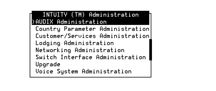
1. Start at the Lucent INTUITY main menu (Figure 1-1).
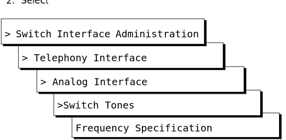
2. Select
The system displays the Frequency Specification window (Figure 1-2) with defaults for your integration. If the parameters have been previously administered, the system displays the current values instead.
Figure 1-2. Frequency Specification Window
3. Enter values in the Frequency used fields, as necessary to represent all the frequencies used for all the tones in your system (see Table 1-1).
NOTE:
You must enter disconnect tone frequencies first. If only one frequency is used for disconnect tone, enter it in the first Frequency used field. If two frequencies are used, enter them first and second.
Frequency Specification >Switch Tones
> Analog Interface > Telephony Interface
Setting Frequencies and Frequency Groups for Call Progress Tones
If all the Frequency used fields are filled and there is no vacant field, the Ringtone frequency field can be deleted and replaced with some other field. If there is a field with no entry, then the disconnect tone entry should be placed in the first Frequency Used field and the ringtone frequency should be deleted.
NOTE:
If you have already completed a tone capture analysis, these values should match the values from the Frequency 1 field and the Frequency 2 field on the "Tone Capture and Analysis Window".
4. In the Group used row, enter frequencies in the Frequency 1 and Frequency 2 fields for frequency group 1 (see Table 1-1).
5. Repeat Step 4 for additional frequency groups that you want to set (see Table 1-1).
6. Enter n in the Dialtone training? field.
7. Press (Save).
The system displays the following message:
Your changes have been saved. You need to restart the Voice System to make these changes active.
8. Press (Acknowledge Message).
9. Press (Cancel) five times to return to the Lucent INTUITY main menu (Figure 1-1).
F3
F1
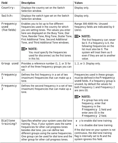
Table 1-1. Frequency Specification Window — Field Descriptions
Field Description Values
Country: Displays the country set on the Switch Selection window.
Display only.
Switch: Displays the switch type set on the Switch Selection window.
Display only.
Frequency used
(five fields)
Enables you to list up to five different frequencies used in the country for which you are setting tones. The values you enter here are displayed on the Busy Tone, Dial Tone, Reorder Tone, Ring Tone, Stutter Tone, First Additional Tone, Second Additional Tone, and Third Additional Tone windows.
NOTE:
You must specify the frequencies used for disconnect as the first tones in this list.
Range 300-4000 Hz. Unused frequency fields are indicated by 0 (zero).
NOTE:
The first frequency can never be 0. If a frequency is 0, the following frequencies on the list must also be 0. The system will treat them as 0 even if they are set to another value.
Group used Provides a reference number (1, 2, or 3) for each of the three frequency groups you can set.
1, 2, or 3. Display only.
Frequency 1
Defines the first frequency in a set of two (maximum) frequencies that can make up a tone.
Frequencies used in these groups
must be defined in the Frequency
used fields. If a frequency group is
unused, by default the values for both Frequency 1 and Frequency 2 are zero (0).
NOTE:
If a group has only one frequency, enter that frequency in the
Frequency 1 field and enter zero (0) in the
Frequency 2 field.
Frequency 2
Defines the second frequency in a set of two (maximum) frequencies that can make up a tone.
Dialtone training?
Specifies whether your system uses dial tone training. Thus, if your system uses the same frequencies for other call progress tones besides dial tone, you can define two different groups using the same frequencies. One group can be used for dial tone and the other group for other call progress tones.
■ y to enable dial tone training
■ n to disable dial tone training
Setting Frequencies and Frequency Groups for Call Progress Tones
Example
Suppose dial tone is 440 Hz + 480 Hz, and you want to assign Group 1 for dial tone. To do so, enter 440 in the Frequency 1 field and 480 in the Frequency 2 field for Group 1. Later when defining dial tone on the Dial Tone window, you can simply specify that it uses Group 1 and the system will recognize the correct frequencies.
Special Considerations for Dial Tone Training
If dial tone training is enabled, the system overwrites the frequencies assigned for dial tone with whatever frequencies dial tone training analysis detects. The system is configured to expect the first frequency or frequencies on the list on the Frequency used field to be for dial tone. If dial tone training detects only one frequency in the dial tone, the system overwrites the first frequency specified. If it detects two frequencies in the dial tone, the system overwrites the first two frequencies.
!
CAUTION:
Any changes to the frequencies made through dial tone training are not indicated on the windows in the user interface.
Problems may arise, however, if the switch tones for in dial tone are not precisely tuned. For example, suppose your system is configured to expect the single frequency of 440 Hz for dial tone and all other tones and that 440 Hz is listed as the first and only frequency in the Frequency Used field. Suppose further that dial tone training detects 441 Hz as the actual frequency sent by the switch. The system overwrites 440 Hz with 441 Hz. In this case, the system will recognize dial tone but not any of the other switch tones.
To ensure that this sort of problem does not occur, it is recommended that you enter the frequency or frequencies used for dial tone more than once in the Frequency used field. In the example above, then entry would be:
If your system uses 350 and 440 Hz, the recommended entry would be:
Setting Parameters for Basic Call
Progress Tones
Use this procedure to set the frequencies and cadence your system recognizes for call progress tones that the switch sends. Parameters can be set for the five basic call progress tones — busy tone, dial tone, reorder tone, ring tone, and stutter tone. Each tone is made up of one or two frequencies and consists of a series of ON and OFF timing cycles, called the cadence.
This procedure also allows you to specify whether the Lucent INTUITY system should interpret the tone you are setting as a disconnect signal (if call progress tones are used for disconnects in your system).
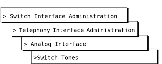
1. Starting at the Lucent INTUITY main menu (Figure 1-1), select
The system displays the Switch Tones menu (Figure 1-3).
Figure 1-3. Switch Tones Menu
2. Select one of the following menu items corresponding to the tone you want to set:
■ Busy Tone
■ Dial Tone
■ Reorder Tone
>Switch Tones > Analog Interface > Telephony Interface
Setting Parameters for Basic Call Progress Tones
■ Ring Tone
■ Stutter Tone
The system displays the appropriate window for the tone you selected with defaults for your integration. If the parameters have been previously administered, the system displays the current values instead. The window also displays the frequency groups set in the Frequency Specification window (Figure 1-2).
NOTE:
Figure 1-4 shows the Dial Tone window. Windows for the other basic tones are identical except for their titles.
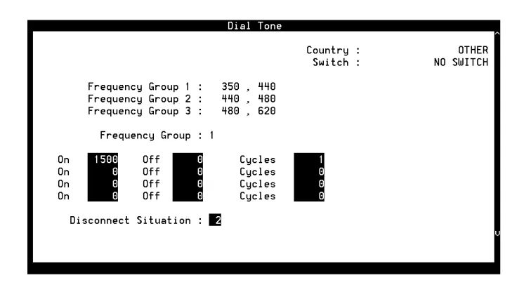
Figure 1-4. Example of Switch Tone Window — Dial Tone
3. In the Frequency group field, select one of the frequency groups (1, 2, or 3) displayed at the top of the window for the system to use for this tone.
NOTE:
4. Enter values in the On, Off, and Cycles fields (see Table 1-2), as necessary to represent the tone cadence. (See the examples following Table 1-2 for information on how to represent the cadence.)
NOTE:
If you set stutter tone, be sure the timing used for continuous tone (minimum on duration) matches the timing used for continuous tone on the dialtone screen. For example, if dialtone is set as continuous tone, minimum 2 seconds, then stutter tone might be 200 msec ON, 200 msec OFF (3 cycles) followed by continuous tone, minimum 2 seconds.
5. Enter the appropriate value in the Disconnect Situation field, depending on whether your system interprets this type of tone as a disconnect signal (see Table 1-2).
6. Press (Save).
The system displays the following message:
Do you wish to continue with this change (Y/N)?
7. Enter y
The system displays the following message:
Your changes been saved. You need to stop and start the Voice System to make these changes active.
8. Press (Acknowledge Message).
9. Do you want to set the frequency and cadence for another tone?
■ If no, press (Cancel) five times to return to the Lucent INTUITY main menu (Figure 1-1). You have completed this procedure.
■ If yes, do the following:
a. Press (Cancel) to return to the Switch Tones menu.
b. Repeat Steps 2 through 9 for the tone you select.
F3
F1
F6
Setting Parameters for Basic Call Progress Tones
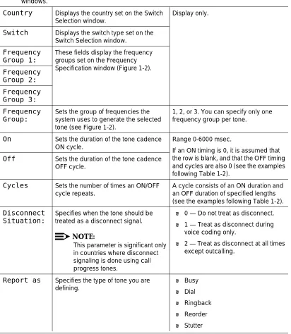
Table 1-2. Basic Tone Windows – Field Descriptions
Field Description Values
NOTE:
These field descriptions apply to all the windows used for setting the five basic call progress tones, including the Busy Tone, Dial Tone, Reorder Tone, Ring Tone, and Stutter Tone windows.
Country Displays the country set on the Switch Selection window.
Display only.
Switch Displays the switch type set on the Switch Selection window.
Frequency Group 1:
These fields display the frequency groups set on the Frequency Specification window (Figure 1-2).
Frequency Group 2: Frequency Group 3: Frequency Group:
Sets the group of frequencies the system uses to generate the selected tone (see Figure 1-2).
1, 2, or 3. You can specify only one frequency group per tone.
On Sets the duration of the tone cadence
ON cycle.
Range 0-6000 msec.
If an ON timing is 0, it is assumed that the row is blank, and that the OFF timing and cycles are also 0 (see the examples following Table 1-2).
Off Sets the duration of the tone cadence
OFF cycle.
Cycles Sets the number of times an ON/OFF cycle repeats.
A cycle consists of an ON duration and an OFF duration of specified lengths (see the examples following Table 1-2).
Disconnect Situation:
Specifies when the tone should be treated as a disconnect signal.
NOTE:
This parameter is significant only in countries where disconnect signaling is done using call progress tones.
■ 0 — Do not treat as disconnect.
■ 1 — Treat as disconnect during
voice coding only.
■ 2 — Treat as disconnect at all times
except outcalling.
Examples
The ON/OFF cycles that make up the cadence of a call progress tone must be specified in order. These examples illustrate how the cadence is set on the basic call progress tone windows.
■ Four rows are needed to specify the following tone:
250 msec ON, 250 msec OFF 500 msec ON, 500 msec OFF 250 msec ON, 250 msec OFF 500 msec ON, 500 msec OFF
■ Three rows are needed for the following tone. Since the first two cycles
repeat exactly (250 msec ON, 250 msec OFF), their setting can be entered once and specified as repeating twice (2 cycles).
250 msec ON, 250 msec OFF 250 msec ON, 250 msec OFF 500 msec ON, 500 msec OFF 250 msec ON, 250 msec OFF
Setting Additional Call Progress Tones
In some cases you may need to assign more than one set of parameters for a certain call progress tone. For example, if your switch and the switch at your public telephone network office use different dial tone parameters, you may need to set both in your INTUITY system.
Use this procedure to set the frequencies and cadence the INTUITY system recognizes for additional call progress tones. As many as three additional tones can be specified as either busy tone, dial tone, reorder tone, ring tone, or stutter tone. Like the basic tones (see "Setting Parameters for Basic Call Progress Tones"), each additional tone is made up of one or two frequencies and consists of a series of on and off timing cycles (cadence).
NOTE:
Unlike for basic tones, here you cannot enable any additional tone you set to be recognized as a disconnect signal.
Setting Additional Call Progress Tones
1. Starting at the Lucent INTUITY main menu (Figure 1-1), select
The system displays the Switch Tones menu (Figure 1-5).
Figure 1-5. Switch Tones Menu
2. Select one of the following menu items corresponding to the additional tone you want to set:
■ First Additional Tone
■ Second Additional Tone
■ Third Additional Tone
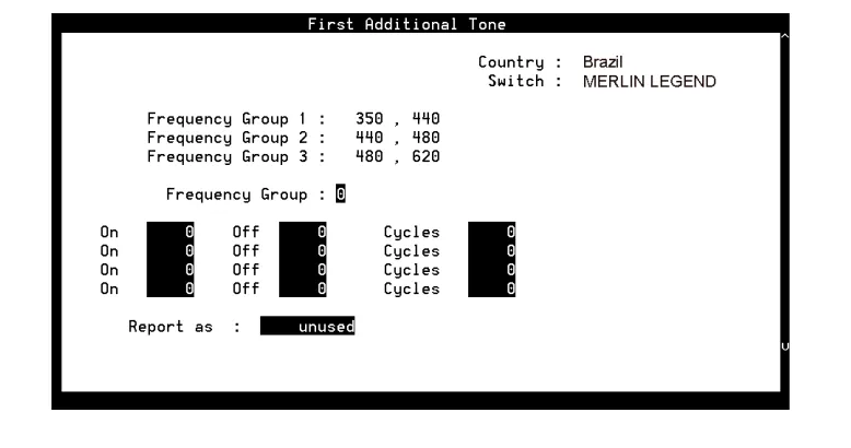
The system displays the appropriate window for the tone you selected. If the parameters have been previously administered, the system displays the current values instead. If the parameters have not been previously administered, the value in the Report as field is unused. The window also displays the frequency groups set in the Frequency Specification window (Figure 1-2).
Figure 1-6 shows the First Additional Tone window. Windows for the other additional tones are identical except for their titles.
>Switch Tones > Analog Interface
Figure 1-6. Example of Additional Tone Window — First Additional Tone
3. In the Frequency Group: field, select one of the frequency groups (1, 2, or 3) displayed at the top of the window for the system to use for this tone (See Table 1-2).
NOTE:
These groups are assigned on the Frequency Specification window.
4. Enter values in the On, Off, and Cycles fields (see Table 1-2), as necessary to represent the tone cadence.
See the examples following Table 1-2 for information on how to represent the cadence.
NOTE:
If you set stutter tone, be sure the timing used for continuous tone (minimum on duration) matches the timing used for continuous tone on the dialtone screen. For example, if dialtone is set as continuous tone, minimum 2 seconds, then stutter tone might be 200 msec ON, 200 msec OFF (3 cycles) followed by continuous tone, minimum 2 seconds.
5. Enter the appropriate tone name in the Report as: field (see Table 1-3), corresponding to the additional basic tone you are defining.
For example, if you are defining an additional dial tone, enter dial
6. Press (Save).
The system displays the following message:
Do you wish to continue with this change (Y/N)?
Setting Additional Call Progress Tones
7. Enter y
The system displays the following message:
Your changes been saved. You need to stop and start the Voice System to make these changes active.
8. Press (Acknowledge Message).
9. Do you want to define another additional tone?
■ If no, press (Cancel) five times to return to the Lucent INTUITY main menu (Figure 1-1). You have completed this procedure.
■ If yes, do the following:
a. Press (Cancel) to return to the Switch Tones menu.
b. Repeat Step 2 through Step 9 for the tone you selected.
10. Press (Cancel) four times to return to the Lucent INTUITY main menu (Figure 1-1).
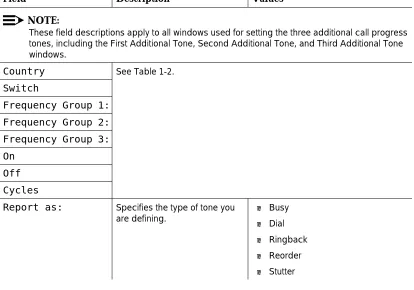
Table 1-3. Additional Tone Windows— Field Descriptions
Field Description Values
NOTE:
These field descriptions apply to all windows used for setting the three additional call progress tones, including the First Additional Tone, Second Additional Tone, and Third Additional Tone windows.
Country See Table 1-2.
Switch
Frequency Group 1:
Frequency Group 2:
Frequency Group 3:
On
Off
Cycles
Report as: Specifies the type of tone you are defining.
■ Busy
■ Dial
■ Ringback
■ Reorder
■ Stutter
F1
F6
F6
Determining Call Progress Tones
Use the Tone Capture and Analysis Screen (Figure 1-7) to evaluate call progress tones on various switches in cases where the system defaults must be tuned. This tool enables you to:
■ Use a set of OPCODE commands to simulates a call scenario that makes
the switch generate a tone
■ Capture the tone
■ Analyze the tone to determine its frequency and cadence
After analysis, you can tune the tone parameters set in the Lucent INTUITY system to match the actual switch parameters by accessing the appropriate window in the telephony interface: Dial Tone, Busy Tone, Reorder Tone, Ringback Tone or Stutter Tone window.
1. Starting at the Lucent INTUITY main menu (Figure 1-1), select
The system displays the Tone Capture and Analysis window (Figure 1-7).
Figure 1-7. Tone Capture and Analysis Window
> Tone Capture and Analysis > Telephony Interface
Determining Call Progress Tones
2. Enter a name for the tone you are to capture (see Table 1-4).
3. Enter commands in the OPCODE, CH No., and PARAMETER fields (see Table 1-5 and the examples following the table.)
NOTE:
Once the cursor is in the commands fields, you can press
(Change Keys) to access keys that allow you to delete a command line (Delete Line), insert a command line (Insert Line), or move the cursor to the Tone field (Home).
Press (Change Keys) again to change to the original keys. Or, if you move the cursor out of the commands fields, the keys
automatically change back.
4. Press (Capture).
The system captures the tone generated by the OPCODE commands.
5. Press (Analyze).
The system analyzes the captured tone and displays its frequency and cadence in the output fields on the window (see Table 1-4).
6. Do you want to save the commands for future use?
■ If no, go to Step 7. ■ If yes, do the following:
a. Press (Save).
The system displays the following message:
Do you wish to continue with this change (y/n)?
b. Enter y
NOTE:
To delete a tone name and its associated commands, position the cursor in the Tone field and press (Delete Tone).
7. Press (Cancel) three times to return to the Lucent INTUITY main menu (Figure 1-1).
F8
F4 F5
F7
F8
F4
F5
F3
F8
.
Table 1-4. Tone Capture and Analysis Window — Input Fields
Field Description Values
TONE Allows you to enter a name for the
tone. Commands for capturing the tone are read from a file using this name. All output files are also generated using this name.
If you save the OPCODE commands associated with this name, they are displayed whenever you enter the name in this field.
Maximum of 10 characters.
FREQUENCY 1: These fields display the result of the tone frequency analysis, which can contain one or two frequency components. Frequency 1 is the lower frequency and Frequency 2 is the upper frequency.
■ If only one component is present,
the Frequency 2 field is blank.
■ If no frequency is detected, both
fields are blank. This may be a result of improper capturing of the tone.
FREQUENCY 2:
ENERGY LEVEL: (two fields)
These fields display the results of analysis of the energy level of each frequency component.
Displayed in dBm.
ON TIME (four fields)
These fields display the results of analysis of the tone cadence ON time.
Displayed in msec.
OFF TIME (four fields)
These fields display the results of analysis of the tone cadence OFF time in.
Displayed in msec.
CYCLES (four fields)
These fields display the results of analysis of the number of
occurrences of the ON time/OFF time cycles.
Integer.
OPCODE Allows you to enter the OPCODE
portion of the OPCODE command syntax.
Specifies the operation to be performed on the channel (seeTable 1-5).
CH. No. Allows you to enter the required
<CH_No.> portion of the OPCODE command syntax.
The port number on the Tip/Ring card.
PARAMETER Allows you to enter the
<PARAMETER> portion of the OPCODE command syntax.
An OPCODE-dependent qualifier. Not required for all OPCODE commands (see Table 1-5). Possible values are:
■ <duration> — Specifies the
number of msec for the operation to be performed.
Determining Call Progress Tones
The system recognizes the following OPCODE commands (Table 1-5).
Examples
The command sequence shown in the window in Figure 1-7 captures dial tone.
The following command sequence captures a busy tone:
Another way to capture busy tone is to do the following:
1. Identify a valid extension number (switch station).
2. Take the station offhook manually. Table 1-5. OPCODE Commands
Command Description
OFFHK <CH_No.> Seizes the specified line.
ONKH <CH_No.> Emulates an on-hook condition on the specified line.
DIAL <CH_No.> <digit_string> Dials out dual-tone multifrequency (DTMF) digits through the specified line.
FLASH <CH_No.> <duration> Performs hook flash on the channel for the specified number of msec.
RECORD <CH_No.> <duration> Captures the pulse code modulation (PCM) data of the voice on the line and stores it in a file. The duration is specified in seconds and should be suitably chosen to capture a sufficient number of on/off cycles of the tone.
PLAY <CH_No.> Plays the stored tone on the specified channel.
WAIT <CH_No.> <duration> Introduces a number of seconds of delay in execution of the next command. This command can be introduced anywhere in the command sequence.
OFFHK 01 124 Make line 01 busy.
DIAL 01 1234 Dial extension number of line 01.
OFFHK 02 126 Cause the switch to inject busy tone on line 02.
DIAL 02 127 Dial extension number of line 02.
RECORD 02 3 Record the tone for 3 seconds.
3. Use the following command sequence:
The following command sequence captures a stutter tone:
The following command sequence captures a ringback tone: OFFHK 01 Make line 01 busy.
DIAL 01 <number that you busied out by taking offhook>
Dial extension <number>.
RECORD 01 10 Record the tone for 10 seconds.
ONHK 01 Unbusy line 01.
OFFHK 01 Make line 01 busy.
RECORD 01 3 Record the tone for 3 seconds.
ONHK 01 Unbusy line 01.
OFFHK 01 Make line 01 busy.
DIAL 01 1234 Dial extension 1234.
RECORD 01 10 Record the tone for 10 seconds.
2
Update for MAP/40P System
Installation
Overview
This chapter is an update to Appendix C, “Troubleshooting Procedures”, in Lucent INTUITY™ Messaging Solutions Release 4 MAP/40P System Installation, 585-310-196.
Purpose
The purpose of this chapter is to provide updated troubleshooting procedures for switch integration.
!
CAUTION:
Tone Customization Update
Due to the frequency limitations of the Lucent INTUITY system, there may be some problems in detecting the far-end disconnect in some countries. Additional administration may be required on the switch to ensure that the far-end disconnect is recognized.
By default, most switches use U.S. parameter settings for different switch tones in all countries. Therefore, all dial tone, busy tone detection, and reorder tones are based on U.S. settings. These tones do not create any problems in the internal call answer function. Problems arise in countries where the disconnect (usually busy) tone is provided by the network.
Therefore, when the voice is being coded or recorded from an external call and the external caller disconnects the call, the Lucent INTUITY system might not be able to do call progress tone detection or to detect the disconnect tone. In this case, the disconnect tone is recorded with the message until Lucent INTUITY finally times out.
NOTE:
This problem does not occur if the public switch network gives a polarity disconnect or wink disconnect. The polarity disconnect or wink disconnect option needs to be ordered from the central office, if possible.
Frequency Specification Update
1. Starting at the Lucent INTUITY main menu (Figure 1-1), select
The system displays the Frequency Specification window (Figure 1-2) with defaults for your integration. If the parameters have been previously administered, the system displays the current values instead.
Frequency Specification >Switch Tones
> Analog Interface > Telephony Interface
Frequency Specification Update
2. Enter values in the Frequency used fields, as necessary to represent all the frequencies used for all the tones in your system (see Table 1-1).
NOTE:
You must enter disconnect tone frequencies first. If only one
frequency is used for disconnect tone, enter it in the first Frequency used field. If two frequencies are used, enter them first and second.
If all the Frequency used fields are filled and there is no vacant field, the Ringtone frequency field can be deleted and replaced with some other field. If there is a field with no entry, then the disconnect tone entry should be placed in the first Frequency Used field and the ringtone frequency should be deleted.
NOTE:
If you have already completed a tone capture analysis, these values should match the values from the Frequency 1 field and the Frequency 2 field on the “Tone Capture and Analysis Window” in Appendix C, “Troubleshooting Procedures”, in Lucent INTUITY
3
Overview
This chapter is an update to Appendix C, “Troubleshooting Procedures”, in Lucent INTUITY™ Messaging Solutions Release 4 MAP/100 System Installation, 585-310-173.
Purpose
The purpose of this chapter is to provide updated troubleshooting procedures for switch integration.
!
CAUTION:
Update for MAP/100 System Installation
Tone Customization Update
Due to the frequency limitations of the Lucent INTUITY system, there may be some problems in detecting the far-end disconnect in some countries. Additional administration may be required on the switch to ensure that the far-end disconnect is recognized.
By default, most switches use U.S. parameter settings for different switch tones in all countries. Therefore, all dial tone, busy tone detection, and reorder tones are based on U.S. settings. These tones do not create any problems in the internal call answer function. Problems arise in countries where the disconnect (usually busy) tone is provided by the network.
Therefore, when the voice is being coded or recorded from an external call and the external caller disconnects the call, the Lucent INTUITY system might not be able to do call progress tone detection or to detect the disconnect tone. In this case, the disconnect tone is recorded with the message until Lucent INTUITY finally times out.
NOTE:
This problem does not occur if the public switch network gives a polarity disconnect or wink disconnect. The polarity disconnect or wink disconnect option needs to be ordered from the central office, if possible.
Frequency Specification Update
1. Starting at the Lucent INTUITYINTUITY main menu (Figure 1-1), select
The system displays the Frequency Specification window (Figure 1-2) with defaults for your integration. If the parameters have been previously administered, the system displays the current values instead.
Frequency Specification >Switch Tones
> Analog Interface > Telephony Interface
2. Enter values in the Frequency used fields, as necessary to represent all the frequencies used for all the tones in your system (see Table 1-1).
NOTE:
You must enter disconnect tone frequencies first. If only one
frequency is used for disconnect tone, enter it in the first Frequency used field. If two frequencies are used, enter them first and second.
If all the Frequency used fields are filled and there is no vacant field, the Ringtone frequency field can be deleted and replaced with some other field. If there is a field with no entry, then the disconnect tone entry should be placed in the first Frequency Used field and the ringtone frequency should be deleted.
NOTE:
If you have already completed a tone capture analysis, these values should match the values from the Frequency 1 field and the Frequency 2 field on the "Tone Capture and Analysis Window" in Appendix C, “Troubleshooting Procedures”, in the Lucent INTUITY
4
Update for Integration with MERLIN
LEGEND Communications System
Overview
This chapter contains additional troubleshooting procedures for switch integration with the MERLIN LEGEND® outside of the U.S. You may need to complete the following procedures if:
■ Disconnect tone is not recognized ■ Dial tone is not detected
■ Outcalling functions, including fax outcalling, do not work ■ Calls are not transferred
NOTE:
See your switch administrator to verify the correct settings for your switch if necessary.
Purpose
Disconnect Tone Is Not Recognized
Due to the frequency limitations of the Lucent INTUITY system, there may be some problems in detecting the far-end disconnect in some countries. Additional administration may be required on the switch to ensure that the far-end disconnect is recognized.
By default, the MERLIN LEGEND uses U.S. parameter settings for different switch tones in all countries. Therefore, all dial tone, busy tone detection, and reorder tones are based on U.S. settings. These tones do not create any problems in the internal call answer function. Problems arise in countries where the disconnect (usually busy) tone is provided by the network.
Therefore, when the voice is being coded or recorded from an external call and the external caller disconnects the call, the Lucent INTUITY system might not be able to do call progress tone detection or to detect the disconnect tone. In this case, the disconnect tone is recorded with the message until Lucent INTUITY system finally times out.
NOTE:
This problem does not occur if the public switch network gives a polarity disconnect or wink disconnect. The polarity disconnect or wink disconnect option needs to be ordered from the central office, if possible.
Additional administration of the switch tones is required for the central
office-based disconnect recognition. This administration can be done on-site for specific cases. This work around could involve a trade-off between detecting MERLIN LEGEND ring tones versus the network disconnects.
The following procedures need to be completed if calls are not disconnected:
■ Tone capture and analysis ■ Frequency specification ■ Tone specification
■ First additional tone specification
Tone Capture and Analysis
There are two methods for Tone Capture and Analysis. These methods are:
■ External call
Disconnect Tone Is Not Recognized
External Call Method
Under this method, a call is made from an outside number to a number on INTUITY AUDIX. This call is received on the channel selected for tone capture. The caller then disconnects and the disconnect tone frequency and cadence is recorded on the Tone Capture and Analysis Screen.
Complete the following procedures for the external call method:
1. Speak to the telephone service providers and get information about the disconnect tone and disconnect frequencies.
2. Starting at the Lucent INTUITY main menu (Figure 1-1), select
The system displays the Tone Capture and Analysis window (Figure 4-1).
Figure 4-1. Tone Capture and Analysis Window
3. Enter a name for the tone you want to capture in the Tone: field. For example, for disconnect not recognized enter disconnect or for dial tone not recognized, enter dial.
> Tone Capture and Analysis > Telephony Interface
4. Under the Commands section enter OFFHK under the OPCODE column. In the Channel Number column enter the channel for which the tone capture and analysis test is to be conducted, example 0.
5. In the next row enter WAIT under the OPCODE column and the same channel number specified in the previous line. Under the parameter column, enter an approximate amount of waiting time, example 2 seconds.
NOTE:
For Dial tone capture and analysis do not enter the Wait OPCODE command.
6. In the consecutive row, enter RECORD under the OPCODE column and the same channel number specified in the previous line. Under the parameter column enter an approximate amount of recording time, example 5 seconds.
7. In the next row, enter ONHK under the OPCODE column and the same channel number specified in the previous line.
8. Get connected to an external telephone line and dial into INTUITY AUDIX. Ensure that the call is received on the channel number on which the tone capture is to be done.
9. Press (Capture). Hang-up on the external call. The system captures the public switch network disconnect tone generated by the central office. The steps that are followed are in the order of the defined OPCODE commands.
10. Press (Analyze). The system analyzes the captured tone and displays its frequency and cadence in the output fields of the window. (See Table 4-1).
NOTE:
If the frequency and the cadence displayed in the output fields match those given by your telephone service provider, save the commands. If the frequency and cadence displayed in the output fields do not match those of your telephone service provider, contact your telephone service provider for additional assistance.
If you do not want to save the commands go to Step 11. If you want to save the commands for future use, do the following:
a. Press (Save).
The system displays the following message:
Do you wish to continue with this change (y/n)?
F4
F5
Disconnect Tone Is Not Recognized
b. Enter y
NOTE:
To delete a tone name and its associated commands, position the cursor in the Tone field and press (Delete Tone).
11. Press (Cancel) three times to return to the Lucent INTUITY main menu (Figure 1-1).
Call Through I
NTUITYAUDIX
Under this method, a call is made from one INTUITY AUDIX channel to another. An external link is established from the specified channel and a call is placed to a number on INTUITY AUDIX. This call is received on the channel selected for tone capture. The caller then disconnects and the disconnect tone frequency and cadence is recorded on the Tone Capture and Analysis Screen.
Complete the following procedures for the calls through INTUITY AUDIX method:
1. Speak to the telephone service providers and get information about the disconnect tone and disconnect frequencies.
2. Starting at the Lucent INTUITY main menu (Figure 1-1), select
The system displays the Tone Capture and Analysis window (Figure 4-2).
F8
F6
> Tone Capture and Analysis > Telephony Interface
Figure 4-2. Tone Capture and Analysis Window for Call Through INTUITY AUDIX Method
3. Enter a name for the tone you want to capture in the Tone: field. For example, for disconnect not recognized enter disconnect or for dial tone not recognized, enter dial.
4. Under the Commands section enter OFFHK under the OPCODE column. In the Channel Number column enter the channel for which the tone capture and analysis test is to be conducted, example 0.
5. In the next row enter DIAL under the OPCODE column and the same channel number specified in the previous line. In the parameter column enter a telephone number which is connected to an INTUITY AUDIX group. Ensure that the digit which is required to connect the user to the external line is also entered, example 9-999 (city code) - 999 (area code) - 9999 (INTUITY AUDIX number). This call should be received on Channel 1 as per example.
6. In the following row enter WAIT under the OPCODE column and the same channel number specified in the previous line, that is 0. Under the parameter column enter an approximate amount of waiting time, example 3 seconds.
NOTE:
For Dial tone capture and analysis do not enter the Wait OPCODE command.
Disconnect Tone Is Not Recognized
8. In the following row enter WAIT under the OPCODE column and the same channel number specified in the previous line, that is 1. Under the parameter column enter an approximate amount of waiting time, example 1 second.
NOTE:
For dial tone capture and analysis do not enter the Wait OPCODE command.
9. In the next row, enter ONHK under the OPCODE column and the same channel number specified in the previous line.
10. In the consecutive row, enter RECORD under the OPCODE column and the same channel number specified for the tone capture and analysis which in this case is 0. Under the parameter column enter an approximate amount of recording time, example 5 seconds.
11. In the next row, enterONHK under the OPCODE column and the same channel number specified in the previous line which, in the example, is 0.
12. Press (Capture).
The system captures the public switch network disconnect tone generated by the central office. The steps that are followed are in the order of the defined OPCODE commands.
13. Press (Analyze).
14. The system analyzes the captured tone and displays its frequency and cadence in the output fields of the window. (See Table 4-1).
NOTE:
If the frequency and the cadence displayed in the output fields match those given by your telephone service provider, save the commands. If the frequency and cadence displayed in the output fields do not match those of your telephone service provider, contact your telephone service provider for additional assistance.
a. If you do not want to save the commands, go to Step 18. If you want to save the commands for future, do the following: Press (Save).
The system displays the following message:
Do you wish to continue with this change (y/n)?
b. Enter y
NOTE:
To delete a tone name and its associated commands, position the cursor in the Tone field and press (Delete Tone).
F4
F5
F3
15. Press (Save).
The system displays the following message:
Do you wish to continue with this change (y/n)?
16. Enter y
17. To delete a tone name and its associated commands, position the cursor in the Tone field and press (Delete Tone).
18. Press (Cancel) three times to return to the Lucent INTUITY main menu (Figure 1-1).
Table 4-1. Tone Capture and Analysis Window
Field Description Values
TONE Allows you to enter a name for the
tone. Commands for capturing the tone are read from a file using this name. All output files are also generated using this name.
If you save the OPCODE commands associated with this name, they are displayed whenever you enter the name in this field.
Maximum of 10 characters.
FREQUENCY 1: These fields display the result of the tone frequency analysis, which can contain one or two frequency components. Frequency 1 is the lower frequency and Frequency 2 is the upper frequency.
■ If only one component is
present, the Frequency 2 field is blank.
■ If no frequency is detected,
both fields are blank. This may be a result of improper capturing of the tone.
FREQUENCY 2:
ENERGY LEVEL: (two fields)
These fields display the results of analysis of the energy level of each frequency component.
Displayed in dBm.
ON TIME (four fields)
These fields display the results of analysis of the tone cadence ON time.
Displayed in msec.
OFF TIME (four fields)
These fields display the results of analysis of the tone cadence OFF time in.
Displayed in msec.
CYCLES (four fields)
These fields display the results of analysis of the number of occurrences of the ON time/OFF time cycles.
Integer.
Continued on next page
F3
F8
Disconnect Tone Is Not Recognized
The system recognizes the following OPCODE commands (Table 4-2). OPCODE Allows you to enter the OPCODE
portion of the OPCODE command syntax.
Specifies the operation to be performed on the channel (seeTable 4-2).
CH. No. Allows you to enter the required
<CH_No.> portion of the OPCODE command syntax.
The port number on the Tip/Ring card.
PARAMETER Allows you to enter the
<PARAMETER> portion of the OPCODE command syntax.
An OPCODE-dependent qualifier. Not required for all OPCODE commands (see Table 4-2). Possible values are:
■ <duration> — Specifies the
number of msec for the operation to be performed.
■ <digit_string> — Specifies a dial string. Valid characters are 0-9, #, and *.
Table 4-2. OPCODE Commands
Command Description
OFFHK <CH_No.> Seizes the specified line.
ONKH <CH_No.> Emulates an on-hook condition on the specified line.
DIAL <CH_No.> <digit_string> Dials out dual-tone multifrequency (DTMF) digits through the specified line.
FLASH <CH_No.> <duration> Performs hook flash on the channel for the specified number of msec.
RECORD <CH_No.> <duration> Captures the pulse code modulation (PCM) data of the voice on the line and stores it in a file. The duration is specified in seconds and should be suitably chosen to capture a sufficient number of on/off cycles of the tone.
PLAY <CH_No.> Plays the stored tone on the specified channel.
WAIT <CH_No.> <duration> Introduces a number of seconds of delay in execution of the next command. This command can be introduced anywhere in the command sequence.
Table 4-1. Tone Capture and Analysis Window — Continued
Field Description Values
Frequency Specification
Complete the following procedure for frequency specification administration:
1. Starting at the Lucent INTUITY main menu (Figure 1-1), select
The system displays the Frequency Specification window (Figure 4-3)
Figure 4-3. Frequency Specification Window
>Frequency Specification
>Switch Tones
>Analog Interface
>Telephony Interface
Disconnect Tone Is Not Recognized
2. Enter values in the Frequency used fields, as necessary to represent all the frequencies used for all the tones in your system (see Table 4-3). These values should be the values from the Frequency 1 and Frequency 2 fields in Figure 4-1.
If all the Frequency used fields are filled and there is no vacant field, the Ringtone frequency field can be deleted and replaced with some other field. If there is a field without an entry, then the disconnect tone entry should be made in the first Frequency used field and the ringtone frequency should be deleted.
NOTE:
You must enter disconnect frequencies first. If the disconnect tone is same as the dial tone, then the dial tone can be entered first. If only one frequency is used for the disconnect tone, enter it in the first Frequency used field. If two frequencies are used, enter them first and second. You can enter the other frequencies your system uses in any order. (See "Example" following Table 4-3 for more
information.)
3. In the Group used row, enter frequencies in the Frequency 1 and Frequency 2 fields for frequency group 1 (see Table 4-3).
Repeat Step 3 for and more frequency groups that you want to set (see Table 4-3).
NOTE:
No more than two frequencies can be specified for disconnect. If more than two frequencies are required, the disconnect tone will not be recognized by the MERLIN LEGEND.
4. The entry in the dialtone training field should be n.
5. Press (Save).
The system displays the following message:
Your changes have been saved. You need to restart the Voice System to make these changes active.
6. Press (Acknowledge Message).
7. Press (Cancel) five times to return to the Lucent INTUITY main menu (Figure 1-1).
F3
F1
Table 4-3. Frequency Specification Window — Field Descriptionse
Field Description Values
Country: Displays the country set on the Switch Selection window.
Display only.
Switch: Displays the switch type set on the Switch Selection window.
Display only.
Frequency used
(five fields)
Enables you to list up to five different frequencies used in the country for which you are setting tones. The values you enter here are displayed on the Busy Tone, Dial Tone, Reorder Tone, Ring Tone, Stutter Tone, First Additional Tone, Second Additional Tone, and Third Additional Tone windows.
NOTE:
You must specify the frequencies used for disconnect as the first two tones in this list. However, if the dial tone frequencies and the disconnect frequencies are the same, then the dial tone frequencies can be placed first.
Range 300-4000 Hz. Unused frequency fields are indicated by 0 (zero).
NOTE:
The first frequency can never be 0. If a frequency is 0, the following frequencies on the list must also be 0. The system will treat them as 0 even if they are set to another value.
Group used Provides a reference number (1, 2, or 3) for each of the three frequency groups you can set.
1, 2, or 3. Display only.
Disconnect Tone Is Not Recognized
Example
Suppose dial tone is 440 Hz + 480 Hz, and you want to assign Group 1 for dial tone. To do so, enter 440 in the Frequency 1 field and 480 in the Frequency 2 field for Group 1. Later when you define dial tone on the Dial Tone window, you can simply specify that it uses Group 1 and the system will recognize the correct frequencies.
Frequency 1
Defines the first frequency in a set of two (maximum) frequencies that can make up a tone.
Frequencies used in these groups must be defined in the
Frequency used fields. If a frequency group is unused, by default the values for both Frequency 1 and Frequency 2 are zero (0).
NOTE:
If a group has only one frequency, enter that frequency in the
Frequency 1 field and enter zero (0) in the Frequency 2 field. Frequency
2
Defines the second frequency in a set of two (maximum) frequencies that can make up a tone.
Dialtone training?
Specifies whether your system uses dial tone training. Thus, if your system uses the same frequencies for other call progress tones besides dial tone, you can define two different groups using the same
frequencies. One group can be used for dial tone and the other group for other call progress tones.
■ y to enable dial tone training
■ n to disable dial tone training
If the dial tone on your system is not continuous, the dial tone training flag is internally set to N and the system ignores this field.
Table 4-3. Frequency Specification Window — Field Descriptionse — Continued
Field Description Values
Tone Specification
Complete the following procedure for dial tone, busy tone, or re-order specification:
1. Starting at the Lucent INTUITY main menu (Figure 1-1), select
The system displays the Switch Tone options menu (Figure 4-4).
Figure 4-4. Switch Tones Menu
From the above menu, select dial tone, busy tone, or reorder tone as required to set the disconnect frequency and cadence. If none of the above options are suitable to set the disconnect frequency cadence, the first additional tone screen can be used.
All of the tone specification screens follow the same format as the Dial Tone screen (Figure 4-5).
Switch Tones
>Analog Interface
>Telephony Interface
Disconnect Tone Is Not Recognized
F
Figure 4-5. Example of Switch Tone Window, Dial Tone
2. In the Frequency group field, select one of the frequency groups (1, 2, or 3) displayed at the top of the window for the system to use for this tone. See Table 4-4 for more information.
NOTE:
These groups are assigned on the Frequency Specification window. See "Frequency Specification".
3. Enter values in the On, Off, and Cycles fields (see Table 4-4) with the values in the "Tone Capture and Analysis Window". The figures need to be rounded off to ensure that if there are minor differences between the frequencies recorded and the frequencies used, the system does not ignore them because the figures are not a perfect match. (See the examples following Table 4-4 for information on how to represent the cadence.)
NOTE:
If you set stutter tone, be sure the timing used for continuous tone (minimum on duration) matches the timing used for continuous tone on the Dial Tone screen. For example, if dial tone is set as
4. Enter the appropriate value in the Disconnect Situation field, depending on whether your system interprets this type of tone as a disconnect signal (see Table 4-4).
5. Press (Save).
The system displays the following message:
Do you wish to continue with this change (Y/N)?
6. Enter y
The system displays the following message:
Your changes been saved. You need to stop and start the Voice System to make these changes active.
7. Press (Acknowledge Message).
8. Do you want to set the frequency and cadence for another tone?
■ If no, press (Cancel) five times to return to the Lucent INTUITY main menu (Figure 1-1). You have completed this procedure.
■ If yes, do the following:
a. Press (Cancel) to return to the Switch Tones menu.
b. Repeat Step 2 through Step 6 for each tone you select.
F3
F1
F6
Disconnect Tone Is Not Recognized
Table 4-4. Basic Tone Windows – Field Descriptions
Field Description Values
NOTE:
These field descriptions apply to all the windows used for setting the five basic call progress tones, including the Busy Tone, Dial Tone, Reorder Tone, Ring Tone, and Stutter Tone windows.
Country Displays the country set on the Switch Selection window.
Display only.
Switch Displays the switch type set on the Switch Selection window.
Frequency Group 1:
These fields display the frequency groups set on the Frequency Specification window (Figure 4-3).
Frequency Group 2: Frequency Group 3: Frequency Group:
Sets the group of frequencies the system uses to generate the selected tone (see Figure 4-3).
1, 2, or 3. You can specify only one frequency group per tone.
On Sets the duration of the tone cadence
ON cycle.
Range 0-6000 msec.
If an ON timing is 0, it is assumed that the row is blank, and that the OFF timing and cycles are also 0 (see the examples following Table 4-4).
Off Sets the duration of the tone cadence
OFF cycle.
Cycles Sets the number of times an ON/OFF cycle repeats.
A cycle consists of an ON duration and an OFF duration of specified lengths (see the examples following Table 4-4).
Disconnect Situation:
Specifies when the tone should be treated as a disconnect signal.
NOTE:
This parameter is significant only in countries where disconnect signaling is done using call progress tones.
■ 0 — Do not treat as disconnect.
■ 1 — Treat as disconnect during
voice coding only.
■ 2 — Treat as disconnect at all times
except outcalling.
Examples
The ON/OFF cycles that make up the cadence of a call progress tone must be specified in order. These examples illustrate how the cadence is set on the basic call progress tone windows.
■ Four rows are needed to specify the following tone:
250 msec ON, 250 msec OFF 500 msec ON, 500 msec OFF 250 msec ON, 250 msec OFF 500 msec ON, 500 msec OFF
■ Three rows are needed for the following tone. Since the first two cycles
repeat exactly (250 msec ON, 250 msec OFF), their setting can b