MERLIN LEGEND
Voice Messaging System
for the MERLIN LEGEND® Communications System
Installation and Upgrade
Lucent Technologies
Document 555-600-100
formerly the communications
Comcode 107734709
systems and technology
Issue 1
Copyright 1996, Lucent Technologies Document 555-600-100
All Rights Reserved Comcode 107734709
Printed in U.S.A. Issue 1
November 1996
Notice
Every effort was made to ensure that the information in this book was complete and accurate at the time of printing. However, information is subject to change.
Your Responsibility for Your System’s Security
Toll fraud is the unauthorized use of your telecommunications system by an unauthorized party, for example, persons other than your company’s employees, agents, subcontractors, or persons working on your company’s behalf. Note that there may be a risk of toll fraud associated with your telecommunications system, and if toll fraud occurs, it can result in substantial additional charges for your telecommunications services.
You and your System Manager are responsible for the security of your system, such as programming and configuring your equipment, to prevent unauthorized use. The System Manager is also responsible for reading all installation, instruction, and system administration documents provided with this product in order to fully understand the features that can introduce risk of toll fraud and the steps that can be taken to reduce that risk. Lucent Technologies does not warrant that this product is immune from or will prevent unauthorized use of common-carrier telecommunication services or facilities accessed through or connected to it. Lucent Technologies will not be responsible for any charges that result from such unauthorized use.
Lucent Technologies Fraud Intervention
If you suspect you are being victimized by toll fraud and you need technical support or assistance, call Technical Service Center Toll Fraud Intervention Hotline at 1 800 643-2353.
Federal Communications Commission Statement
This equipment has been tested and found to comply with the limits for a Class A digital device, pursuant to Part 15 of the FCC Rules. These limits are designed to provide reasonable protection against harmful interference when the equipment is operated in a commercial environment. This equipment generates, uses, and can radiate radio frequency energy and, if not installed and used in accordance with the instruction manual, may cause harmful interference to radio communications. Operation of this equipment in a residential area is likely to cause harmful interference, in which case the user will be required to correct the interference at his own expense.
Canadian Department of Communications (DOC) Interference Information
This digital apparatus does not exceed the Class A limits for radio noise emissions set out in the radio interference regulations of the Canadian Department of Communications.
Le Présent Appareil Numérique n’émet pas de bruits radioélectriques dépassant les limites applicables aux appareils numériques de la class A préscrites dans le reglement sur le brouillage radioélectrique édicté par le ministère des Communications du Canada.
Trademarks
MERLIN LEGEND, MERLIN, MERLIN MAIL, MLX-10, MLX-10D, MLX-10DP, MLX-28D, and MLX-20L are registered trademarks and MLX-16DP is a trademark of Lucent Technologies in the U.S. and other countries.
Ordering Information
Call: Lucent Technologies Publications Center
Voice 1 800 457-1235 International Voice 317 361-5353 Fax 1 800 457-1764 International Fax 317 361-5355
Write: Lucent Technologies Publications Center P.O. Box 4100
Crawfordsville, IN 47933
Order: Document No. 555-600-100, Issue 1, November 1996, Comcode 107734709 Support Telephone Number
In the continental U.S., Lucent Technologies provides a toll-free customer helpline 24 hours a day. Call the Lucent Technologies Helpline at
1 800 628-2888 or your Lucent Technologies authorized dealer if you need assistance when installing, programming, or using your system. Consultation charges may apply. Outside the continental U.S., contact your local Lucent Technologies authorized representative.
Heritage Statement
Lucent Technologies — formed as a result of AT&T’s planned restructuring — designs, builds, and delivers a wide range of public and private networks, communication systems and software, consumer and business telephone systems, and microelectronics components. The world-renowned Bell Laboratories is the research and development arm for the company.
Disclaimer
Intellectual property related to this product and registered to AT&T Corporation has been transferred to Lucent Technologies, Inc.
!
WARNING:This book is intended for trained technicians only.
ONLY an authorized Lucent Technologies technician or authorized dealer shall install, set hardware options, or repair this product.
DO NOT attempt to install or remove this product.
Contents
i
1
Introduction
1-1Overview of the MERLIN LEGEND MAIL System 1-1
Using This Guide 1-9
Related Documents 1-11
2
Installing the MERLIN LEGEND MAIL
System
2-1Overview 2-1
Prepare for Installation 2-1
Installation 2-3
3
Upgrading the MERLIN LEGEND MAIL
System
3-1Overview 3-1
Installing a Voice-Port Card 3-2
Replacing the Disk Drive 3-4
Replacing a Two-Port or Four-Port Voice-Port
Card 3-6
Replacing a MERLIN LEGEND MAIL Module 3-7 Replacing an existing MERLIN MAIL VMS with a
MERLIN LEGEND MAIL Module 3-9
4
Acceptance Tests and Troubleshooting
4-1Overview 4-1
Performing Acceptance Tests 4-2
Troubleshooting 4-3
A
Ordering Codes
A-1Overview A-1
Contents
B
Busying Out/Restoring the Module
B-1Overview B-1
Busying Out the Module B-1
Restoring the Module B-3
C
Installing/Removing the Module
C-1Overview C-1
Installing the Module C-2
Removing the Module C-2
D
Using the Serial Number Utility
D-1Overview D-1
Re-Serializing the Disk Drive D-2
E
Resetting the System
E-1Overview E-1
Resetting the MERLIN LEGEND MAIL Module E-1 Resetting the Remote Maintenance Device E-2
F
Changing the Far-End Disconnect Setting
and Adding a 3 db Boost
F-1Overview F-1
Changing the Far-End Disconnect Setting F-1
Adding a 3 db Boost F-4
Figures
iii
1
Introduction
1-11-1. MERLIN LEGEND MAIL Module with a Four-Port
Expansion Voice-Port Card 1-3
1-2. Two-Port Voice-Port Expansion Card 1-5 1-3. Four-Port Voice-Port Expansion Card 1-6
3
Upgrading the MERLIN LEGEND MAIL
System
3-13-1. Sliding Voice-Port Card into Module 3-3
3-2. Removing Disk Drive Assembly 3-4
3-3. Disk Drive Assembly 3-5
F
Changing the Far-End Disconnect Setting
and Adding a 3 db Boost
F-1F-1. Removing Disk Drive Assembly F-2
F-2. Location of Switches for Far-End Disconnect
Introduction
1
Overview of the MERLIN LEGEND
MAIL System
The MERLIN LEGEND® MAIL Voice Messaging System provides the same features and functionality as the MERLIN MAIL® Voice Messaging System Release 3.0. However, its integrated design houses both the station port and the voice mail functionality in a single module that plugs into the MERLIN LEGEND backplane.
This new module replaces the hardware previously required to provide the same voice messaging service: an 012 module, separate MERLIN MAIL R3 system, and remote maintenance device. Figure 1-1 shows the MERLIN LEGEND MAIL module with a four-port expansion voice-port card.
System Compatibility
The MERLIN LEGEND MAIL system is compatible with all domestic and international releases of the MERLIN LEGEND Communications System. The MERLIN LEGEND MAIL system is not compatible with MERLIN II systems.
NOTE:
The MERLIN LEGEND system must have a 391A3 or newer power supply module.
System Capacities
Introduction
1-2
Introduction
System Components
The MERLIN LEGEND MAIL system consists of one module that resembles a MERLIN LEGEND system 012 module with no modular jacks and resides in the MERLIN LEGEND system carrier. The MERLIN LEGEND MAIL system module consists of three subassemblies and their components:
a base module (which provides two touch-tone receivers and a 1200-baud remote maintenance device)
Similar to an 012 module, the MERLIN LEGEND MAIL module is equipped with two touch tone receivers (TTRs) that are available as MERLIN LEGEND system resources.
The internal remote maintenance device (RMD) is used for answering inbound remote maintenance calls. It is connected to port 7 of the MERLIN LEGEND MAIL module and to the COM serial port of the voice mail central processing unit. The default settings for the RMD are Auto Answer ON, 1200 baud, 8 data bits, 1 stop bit, and no parity.
The base module also contains the following components:
a nine-pin serial port that enables you to connect a PC to the MERLIN LEGEND MAIL module
The COM port can be accessed from the front edge of the MERLIN LEGEND MAIL module with a DCE DB-9 connector. When a nine-pin straight-through cable is attached to the DB-9 connector, the module automatically switches the COM port from the modem to the DB-9 connector.
LEDs
The green LED on the bottom of the module is the system status LED. It is ON when the MERLIN LEGEND MAIL system is operating
properly. It blinks when there is a problem with the MERLIN LEGEND MAIL system (for example, a problem with the disk drive on which the system software resides). Additional LEDs associated with the voice mail ports are explained in the following sections describing the two-port, four-two-port, and six-port systems.
two reset buttons
There are two reset buttons on the MERLIN LEGEND MAIL module (see Figure 1-1). One button controls the system, and the other controls the modem. The VM Reset button (System Reset button) causes the voice mail system to reboot and reinitialize the voice mail functions. It has no effect on the modem. Conversely, the RMD Reset button causes only the modem to reset. You can use a straightened paper clip or other similar pointed instrument to press the reset button. a detachable disk drive that stores all of the voice mail messages for the MERLIN LEGEND MAIL system
Introduction
1-4
Description of the Two-Port MERLIN LEGEND MAIL System
The two-port MERLIN LEGEND MAIL system includes the base module, hard disk, which provides 21 hours of message storage, and two voice ports.
Port Assignments
The ports on the two-port MERLIN LEGEND MAIL system are assigned as follows:
port 1 - voice mail port 2 - voice mail
port 7 - remote maintenance device
Ports 8 through 12 are not installed, and ports 3, 4, 5, and 6 are not equipped.
NOTE:
The ports on a MERLIN LEGEND MAIL module are numbered from top to bottom (that is, port 1 is the top-most port on the module).
LED Meanings
Table 1-1 summarizes the meaning of the five LEDs on the two-port base unit.
NOTE:
The green LED on the bottom of the module is the system status LED. It is ON when the MERLIN LEGEND MAIL system is operating properly.
The additional two pairs of GREEN-RED LEDs (labeled VM1 and VM2) are the same as those for MERLIN MAIL.
Table 1-1. MERLIN LEGEND MAIL LED Meanings
Red LED Green LED Meaning
OFF ON On-hook; waiting for a call
ON OFF Off hook; speaking or recording
ON ON/BLINK
(momentarily)
Off hook; receiving touch tone
OFF OFF Fault condition
Introduction
Description of the Four-Port MERLIN LEGEND MAIL System
The four-port MERLIN LEGEND MAIL system includes the base module, hard disk, which provides 21 hours of message storage, and four voice ports. The two-port voice-port card required for this system is shown in Figure 1-2.
Figure 1-2. Two-Port Voice-Port Expansion Card
Port Assignments
The ports on the four-port MERLIN LEGEND MAIL system are assigned as follows:
port 1 - voice mail port 2 - voice mail port 3 - voice mail port 4 - voice mail
port 7 - remote maintenance device
Ports 8 through 12 are not installed, and ports 5 and 6 are not equipped.
NOTE:
The ports on a MERLIN LEGEND MAIL module are numbered from top to bottom (that is, port 1 is the top-most port on the module).
LED Meanings
Introduction
1-6
Description of the Six-Port MERLIN LEGEND MAIL System
The six-port MERLIN LEGEND MAIL system includes the base module, hard disk, which provides 21 hours of message storage, and voice ports. The four-port expansion voice-four-port card required for this system is shown in Figure 1-3.
Figure 1-3. Four-Port Voice-Port Expansion Card
Port Assignments
The ports on the six-port MERLIN LEGEND MAIL system are assigned as follows:
port 1 - voice mail port 2 - voice mail port 3 - voice mail port 4 - voice mail port 5 - voice mail port 6 - voice mail
port 7 - remote maintenance device
Ports 8 through 12 are not installed.
NOTE:
Introduction
LED Meanings
On the six-port MERLIN LEGEND MAIL system, the four-port expansion voice-port card has four pairs of LEDs (labeled VM3, VM4, VM5, and VM6). The meaning of these LEDs is the same as for the LEDs labeled VM1 and VM2. (See Table 1-1.)
The MERLIN LEGEND MAIL System Advantages
The new integrated design of the MERLIN LEGEND MAIL system offers several advantages. For example, it
eliminates the need to cable two, four, or six voice mail ports as well as the remote maintenance device, which are now hard-coded within the module;
simplifies remote maintenance because the station number associated with the remote maintenance device can be deduced by examining MERLIN LEGEND translations;
eliminates the need to provide surge/lightning protection for the voice mail system;
Introduction
1-8
MERLIN LEGEND MAIL System Specifications
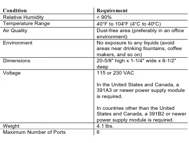
Before installing the MERLIN LEGEND MAIL module, be sure that your installation site meets the environmental requirements provided in Table 1-2.
Table 1-2. MERLIN LEGEND MAIL System Specifications
Condition Requirement
Relative Humidity < 90%
Temperature Range 40°F to 104°F (4°C to 40°C)
Air Quality Dust-free area (preferably in an office
environment)
Environment No exposure to any liquids (avoid
areas near drinking fountains, coffee makers, and so on)
Dimensions 20-5/8" high x 1-1/4" wide x 8-1/2" deep
Voltage 115 or 230 VAC
In the United States and Canada, a 391A3 or newer power supply module is required.
In countries other than the United States and Canada, a 391B2 or newer power supply module is required.
Weight 4.1 lbs.
Introduction
Using This Guide
This guide provides the installation, upgrade, troubleshooting, and ordering information for the MERLIN LEGEND MAIL system. The information in this guide replaces the existing installation, upgrade, and ordering information in Chapter 2, Chapter 7, and Appendix G of the MERLIN MAIL® Voice Messaging
System Release 3 Planning, Installation, and Use (AT&T 585-320-142). This
guide also includes acceptance test procedures that supplement those provided in the MERLIN MAIL® Voice Messaging System Release 3 Planning, Installation,
and Use. Be sure to use this guide with your MERLIN MAIL Voice Messaging
System Release 3 documentation.
NOTE:
This guide is intended only for qualified technicians. This guide is not intended for customers.
This guide consists of the following chapters: Chapter 1: Introduction
This chapter provides an overview of the MERLIN LEGEND MAIL system.
Chapter 2: Installing the MERLIN LEGEND MAIL System
This chapter describes how to install the MERLIN LEGEND MAIL module. This chapter replaces the information in Chapter 2 of the MERLIN MAIL® Voice Messaging System Release 3 Planning, Installation, and Use
(AT&T 585-320-142).
Chapter 3: Upgrading the MERLIN LEGEND MAIL System
This chapter describes how to upgrade the number of voice mail ports. It includes instructions for installing the expansion module and for replacing the hard disk in the MERLIN LEGEND MAIL module, the module itself, and any defective expansion modules. This chapter replaces the
information in Chapter 7 of the MERLIN MAIL® Voice Messaging System Release 3 Planning, Installation, and Use
(AT&T 585-320-142).
Chapter 4: Performing Acceptance Tests and Troubleshooting
This chapter describes how to perform acceptance tests to verify proper operation of the RMD, disk drive, and voice ports. These tests are intended only to supplement the instructions for performing acceptance tests detailed in Chapter 6 of the MERLIN MAIL® Voice Messaging
System Release 3 Planning, Installation, and Use (AT&T 585-320-142).
Introduction
1-10
Appendix A: Ordering Information
This appendix provides the ordering codes for the MERLIN LEGEND MAIL system. This appendix replaces the information in Appendix G of
the MERLIN MAIL® Voice Messaging System Release 3 Planning,
Installation, and Use (AT&T 585-320-142).
Appendix B: Busying Out/Restoring the Module
This appendix provides the step-by-step instructions for busying out and restoring the MERLIN LEGEND MAIL module. These instructions are cross-referenced in the installation procedures provided in Chapter 2 of this guide.
Appendix C: Installing/Removing the Module
This appendix provides the step-by-step instructions for installing and removing the MERLIN LEGEND MAIL module. These instructions are cross-referenced throughout upgrade procedures provided in Chapter 3 of this guide.
Appendix D: Using the Serial Number Utility
This appendix provides the step-by-step instructions for re-serializing the disk drive. These instructions are cross-referenced in the upgrade procedures provided in Chapter 3 of this guide.
Appendix E: Resetting the System
This appendix provides the step-by-step instructions for resetting the MERLIN LEGEND MAIL module and RMD. These instructions are cross-referenced throughout the upgrade procedures provided in Chapter 3 of this guide.
Appendix F: Changing the Far-End Disconnect Setting and Adding a 3 db Boost
This appendix provides the step-by-step instructions for changing the far-end disconnect setting and adding a 3 db boost.
NOTE:
Introduction
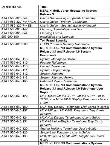
Related Documents
The documents listed below are MERLIN MAIL Voice Messaging System documents or part of the MERLIN LEGEND Communications System documentation set. These documents can be ordered from the Lucent Technologies Publications Center by calling 1-800-457-1235.
Table 1-3. MERLIN MAIL Voice Messaging System Release 3 and MERLIN LEGEND Communications System Release 3.1 and Release 4.1 Documentation Set
Document No. Title
MERLIN MAIL Voice Messaging System Release 3
AT&T 585-320-744 User's Guide—English (North American)
AT&T 585-320-744FRCA User's Guide—French (Canadian)
AT&T 585-320-744ES User's Guide—Spanish (Latin American)
AT&T 585-320-142 Planning, Installation, and Use
AT&T 585-320-544 Planning Forms
555-600-100 Installation and Upgrade
Toll Fraud Security
AT&T 555-025-600 GBCS Products Security Handbook
MERLIN LEGEND Communications System Release 3.1 and Release 4.0 System
Documents
AT&T 555-640-118 System Manager's Guide
AT&T 555-640-110 Feature Reference
AT&T 555-640-116 Pocket Reference
AT&T 555-640-111 System Programming
AT&T 555-640-112 System Planning
AT&T 555-640-113 System Planning Forms
AT&T 555-640-105 Data and Video Reference
MERLIN LEGEND Communications System Release 3.1 and Release 4.0 Telephone User Support
AT&T 555-640-122 10D®, 10DP™, 16DP™, MLX-28D®, and MLX-20L® Display Telephones User's Guide
AT&T 555-640-150 MLX-10D Display Telephone Tray Cards (5 cards)
AT&T 555-640-152 MLX-28D and MLX-20L Telephone Tray Cards (5 cards)
AT&T 555-640-124 MLX Non-Display Telephones User's Guide
AT&T 555-640-151 MLX-10® Non-Display Telephone Tray Cards (6 cards)
AT&T 555-640-120 Analog Multiline Telephone User's Guide
AT&T 555-640-126 Single-Line Telephone User's Guide
AT&T 555-640-138 MDC 9000 and MDW 9000 Telephones User's Guide
Introduction
1-12
Release 3.1 and Release 4.0 Operator Support AT&T 555-640-134 MLX Direct-Line Console Operator's Guide
AT&T 555-640-132 Analog Direct-Line Console Operator's Guide
AT&T 555-640-136 MLX Queued Call Console Operator's Guide
MERLIN LEGEND Communications System Release 3.1 and Release 4.0 Miscellaneous User Support
AT&T 555-640-130 Calling Group Supervisor's Guide
MERLIN LEGEND Communications System Release 3.1 and Release 4.0 Documentation for Qualified Technicians
Installing the MERLIN
LEGEND MAIL System
2
Overview
This chapter describes how to install a new MERLIN LEGEND MAIL module.
!
WARNING:The procedures in this chapter are intended for qualified technicians only.
Prepare for Installation
Before you begin, verify that you have:
the required MERLIN LEGEND MAIL system components (see "System Components" in Chapter 1)
an installation site that meets the environmental requirements for MERLIN LEGEND MAIL (see "MERLIN LEGEND MAIL System Specifications" in Chapter 1)
the MERLIN LEGEND Communications system equipment required, including
a domestic release of the MERLIN LEGEND Communications System that is functioning properly and has a 391A3 or newer power supply module
Installing the MERLIN LEGEND MAIL System
2-2
The MERLIN LEGEND system treats the MERLIN LEGEND MAIL module like an 012 module. When installed, the module has a default of 12 extension numbers that are based on the carrier slot in which the module is located. Though the MERLIN LEGEND MAIL module provides 12 ports, only ports 1 through 7 are used by the MERLIN MAIL system. See Chapter 1 for a description of the port assignments.
NOTE:
Installing the MERLIN LEGEND MAIL System
Installation
When installing the MERLIN LEGEND MAIL module, keep in mind the following: Make sure the MERLIN LEGEND system has a 391A3 or newer power supply module. MERLIN LEGEND MAIL does not support the 391A1 and 391A2 power supply modules.
Install the MERLIN LEGEND MAIL module in the first available slot following the installation of other modules in the MERLIN LEGEND system carrier to avoid gaps in the customer's extension dial plan. Do not leave an empty slot between the right-most module and the MERLIN LEGEND MAIL module. The MERLIN LEGEND system will ignore modules installed beyond any empty slot.
!
CAUTION:To prevent damage from electrostatic discharge (ESD), avoid touching leads, connectors, pins, and other components. Use a properly grounded wrist strap.
To install MERLIN LEGEND MAIL:
1. Install a completely configured MERLIN LEGEND MAIL module (that is, the correct number of ports physically installed) into the first empty slot in the MERLIN LEGEND system carrier. See Appendix C.
2. Program the MERLIN LEGEND module by following the instructions in Chapter 3 of the MERLIN MAIL® Voice Messaging System Release 3
Planning, Installation, and Use (AT&T 585-320-142).
3. Program the MERLIN LEGEND system by following instructions in Chapter 4 of the MERLIN MAIL® Voice Messaging System Release 3
Planning, Installation, and Use (AT&T 585-320-142). When programming
the RMD, remember that the RMD is port 7 and uses the corresponding extension.
4. Program the internal remote maintenance device by performing the following steps:
a. (Key mode only) Remove all lines from the RMD. To do this, enter programming mode, select Extensions, then Lines/Trunks and follow the prompts. For Hybrid/PBX mode, skip this step.
b. Restrict the RMD from making outside calls. To do this, enter MERLIN LEGEND System Programming, select Extensions then
Restriction and follow the prompts. For Restriction Type, choose
Outward Restrict .
!
Security Alert:Installing the MERLIN LEGEND MAIL System
2-4
5. Perform the acceptance tests in Chapter 4 of this document and also the acceptance tests in Chapter 6 of the MERLIN MAIL® Voice Messaging
Upgrading the MERLIN
LEGEND MAIL System
3
Overview
This chapter describes how to
upgrade the number of voice mail ports in the MERLIN LEGEND MAIL module
replace the disk drive in the MERLIN LEGEND MAIL module replace the voice-port card in the MERLIN LEGEND MAIL module replace the MERLIN LEGEND MAIL module
replace an existing MERLIN MAIL Voice Messaging System with a MERLIN LEGEND MAIL module
!
WARNING:The procedures in this chapter are intended for qualified technicians only.
!
CAUTION:Upgrading the MERLIN LEGEND MAIL System
3-2
Installing a Voice-Port Card
Customers with a two-port or four-port configuration may want to upgrade to a four-port or six-port configuration to support more subscribers or a greater volume of calls. The MERLIN LEGEND MAIL system can have a maximum of six ports. Depending on your system, you can make the following upgrades:
upgrade from a two-port system to a four-port system upgrade from a two-port system to a six-port system upgrade from a four-port system to a six-port system
The two-port MERLIN LEGEND MAIL module can be upgraded with a two-port voice-port card to provide four ports or upgraded with a four-port voice-port card to provide six ports. The four-port MERLIN LEGEND MAIL module can be upgraded by replacing the two-port voice card with a four-port voice card to provide six ports.
!
CAUTION:To prevent damage from electrostatic discharge (ESD), avoid touching leads, connectors, pins, and other components. Use a properly grounded wrist strap.
To install a voice-port card:
1. Examine the module to determine its current configuration.
If there are no "holes" (for LEDs) in the voice-port card cover, there is no voice-port card installed. You can install either a two-port or a four-port voice-four-port card. Proceed to Step 2.
If there are 4 LEDs in the voice-port card cover, a two-port voice-port card is installed already. To upgrade, you must remove the two-port voice-port card and replace it with a four-port voice-port card. Proceed to Step 2.
If there are eight LEDs in the port card cover, a four-port voice-port card is installed already. No further upgrade is possible.
2. Busy out the slot in which the MERLIN LEGEND MAIL module is installed. See Appendix B.
3. Remove the MERLIN LEGEND MAIL module. See Appendix C. 4. Pull out both pushpin-like "handles" on the voice-port card cover
approximately 1/8 of an inch to the next position. 5. Remove the cover.
If a voice-port card is installed already, proceed to Step 6.
Upgrading the MERLIN LEGEND MAIL System
6. Unplug the voice-port card by sliding it out all of the way.
7. Install the upgrade voice-port card by sliding the card into the card slots, and seating it in the MERLIN LEGEND MAIL module (Figure 3-1). Do not push on the two handles; instead, push on the center of the plastic cover. NOTE:
The voice-port card must be correctly oriented to be installed properly. If the card stops about 3/8 of an inch prior to being seated, it is not installed properly. (It is probably installed upside down.) If this occurs, remove the voice-port card, rotate it, and then try to install the voice-port card again.
Figure 3-1. Sliding Voice-Port Card into Module
8. After the voice-port card is seated correctly, push down on the two plastic handles. You should hear a click when each handle is in place.
9. Reinstall the MERLIN LEGEND MAIL module. See Appendix C. 10. Restore the slot. See Appendix B.
11. Administer the new ports on the MERLIN LEGEND system. Refer to Chapter 4 of the MERLIN MAIL® Voice Messaging System Release 3
Upgrading the MERLIN LEGEND MAIL System
3-4
Replacing the Disk Drive
This section describes how to replace the disk drive in the MERLIN LEGEND MAIL module.
!
CAUTION:Before touching leads, connectors, pins, and other components when handling the disk drive, use a properly grounded wrist strap to prevent damage from electrostatic discharge (ESD).
To replace the disk drive:
1. Busy out the slot in which the MERLIN LEGEND MAIL module is installed. See Appendix B.
2. Remove the MERLIN LEGEND MAIL module. See Appendix C. 3. Place the MERLIN LEGEND MAIL module on its side with the six-sided
cutout (with two metal handles) facing up (Figure 3-2).
4. Grasp the two metal handles and gently wriggle the part attached to the handles out of its connectors (Figure 3-2). This is the disk drive assembly (Figure 3-3).
Upgrading the MERLIN LEGEND MAIL System
Figure 3-3. Disk Drive Assembly
5. Plug the new disk drive assembly into the MERLIN LEGEND MAIL module.
6. Reinstall the MERLIN LEGEND MAIL module. See Appendix C. 7. Restore the slot. See Appendix B.
8. Using the Serial Number Utility, re-serialize the disk drive to match the serial number that is listed on the bar code label on the top of the MERLIN LEGEND MAIL module. See Appendix D.
9. Reprogram the voice mail system. See Chapter 3 of the MERLIN MAIL® Voice Messaging System Release 3 Planning, Installation, and Use (AT&T
Upgrading the MERLIN LEGEND MAIL System
3-6
Replacing a Two-Port or Four-Port
Voice-Port Card
This section describes how to replace a two-port or four-port voice-port card (if it is defective) in a MERLIN LEGEND MAIL module.
!
CAUTION:To prevent damage from electrostatic discharge (ESD), avoid touching leads, connectors, pins, and other components. Use a properly grounded wrist strap.
To replace a defective two-port or four-port voice-port card: 1. Determine which voice port is defective.
If the defective voice port is port 3, 4, 5, or 6, proceed to Step 2.
If the defective voice port is port 1 or 2, the MERLIN LEGEND MAIL module must be replaced. Proceed to "Replacing a MERLIN LEGEND MAIL Module."
2. Busy out the slot in which the MERLIN LEGEND MAIL module is installed. See Appendix B.
3. Remove the MERLIN LEGEND MAIL module. See Appendix C. 4. Pull out both pushpin-like "handles" on the voice-port card cover
approximately 1/8 of an inch to the next position.
5. Unplug the voice-port card attached by sliding it out all of the way. 6. Install the replacement voice-port card by sliding the card into the card
slots, and seating it in the MERLIN LEGEND MAIL module (Figure 3-1). Do not push on the two handles; instead, push on the center of the plastic cover.
NOTE:
The voice-port card must be correctly oriented to be installed properly. If the card stops about 3/8 of an inch prior to being seated, it is not installed properly. (It is probably installed upside down.) If this occurs, remove the voice-port card, rotate it, and then try to install the voice-port card again.
7. After the voice-port card is seated correctly, push down on the two plastic handles. You should hear a click when each handle is in place.
Upgrading the MERLIN LEGEND MAIL System
Replacing a MERLIN LEGEND MAIL
Module
This section describes how to replace a MERLIN LEGEND MAIL module that is defective (for example, port 1 or port 2 is defective or the clock battery is bad). You will want to retain the disk drive from the defective unit so that the
customer's messages, greetings, and programming are not lost.
!
CAUTION:Before touching leads, connectors, pins, and other components when handling the disk drive, use a properly grounded wrist strap to prevent damage from electrostatic discharge (ESD).
!
CAUTION:Although the system is designed for modules to be removed and replaced without affecting call processing, there is still a possibility that partially removing or inserting a module can cause a cold start of the MERLIN LEGEND system.
To replace a MERLIN LEGEND MAIL module:
1. Busy out the slot in which the MERLIN LEGEND MAIL module is installed. See Appendix B.
2. Remove the MERLIN LEGEND MAIL module. See Appendix C.
3. Place the MERLIN LEGEND MAIL module on its side with the six-sided cutout (with two metal handles) facing up (Figure 3-2).
4. Grasp the two metal handles and gently wriggle the part attached to the handles out of its connectors (Figure 3-2). This is the disk drive assembly (Figure 3-3). Place the disk drive to the side. Later, you will install the disk drive into the replacement MERLIN LEGEND MAIL module.
5. Examine the module to determine its current configuration.
If there are no "holes" (for LEDs) in the voice-port card cover, there is no voice-port card installed. Proceed to Step 6.
If there are LEDs in the voice-port card cover, a voice-port card is installed already. To remove the voice-port card:
a. Pull out both pushpin-like "handles" on the voice-port card cover approximately 1/8 of an inch to the next position.
Upgrading the MERLIN LEGEND MAIL System
3-8
6. Take the replacement MERLIN LEGEND MAIL module out of its bag.
If you are not installing a voice-port card, proceed to Step 7.
If you are installing a voice-port card (that is, either a new voice-port card or the voice-port card from the old MERLIN LEGEND MAIL module), perform the following steps:
a. Pull out both pushpin-like "handles" on the voice-port card cover approximately 1/8 of an inch to the next position.
b. Install the upgrade or replacement voice-port card by sliding the card into the card slots, and seating it in the MERLIN LEGEND MAIL module (Figure 3-1). Do not push on the two handles; instead, push on the center of the plastic cover.
NOTE:
The voice-port card must be correctly oriented to be installed properly. If the card stops about 3/8 of an inch prior to being seated, it is not installed properly. (It is probably installed upside down.) If this occurs, remove the voice-port card, rotate it, and then try to install the voice-port card again.
c. After the voice-port card is seated correctly, push down on the two plastic handles. You should hear a click when each handle is in place.
7. Place the replacement MERLIN LEGEND MAIL module on its side with the six-sided cutout (with two metal handles) facing up (Figure 3-2). 8. Grasp the two metal handles and pull up (Figure 3-2).
9. Plug the disk drive assembly from the old MERLIN LEGEND MAIL module into the replacement module.
10. Install the replacement MERLIN LEGEND MAIL module. See Appendix C.
11. Restore the slot. See Appendix B.
Upgrading the MERLIN LEGEND MAIL System
Replacing an existing MERLIN MAIL
VMS with a MERLIN LEGEND MAIL
Module
To replace an existing MERLIN MAIL Voice Messaging System with a MERLIN LEGEND MAIL module:
1. Install a completely configured MERLIN LEGEND MAIL module (that is, the correct number of ports physically installed) into the first empty slot in the MERLIN LEGEND system carrier. See Appendix C.
2. Following the instructions in Chapter 3 of the MERLIN MAIL® Voice Messaging System Release 3 Planning, Installation, and Use
(AT&T 585-320-142), program the MERLIN LEGEND MAIL module using
a temporary VMI group and the first port.
3. When you are finished programming the sample VMI group, remove it. 4. Determine which VMI calling group is used for mail.
5. Remove the “old” MERLIN MAIL system extensions from the VMI group. 6. Add the new extensions associated with the mail system by following the instructions in “Preparing the MERLIN LEGEND Communications System for MERLIN MAIL System Programming” in Chapter 3 of the MERLIN MAIL® Voice Messaging System Release 3 Planning, Installation, and
Use(AT&T 585-320-142).
7. Perform each procedure in Chapter 4 of the MERLIN MAIL® Voice Messaging System Release 3 Planning, Installation, and Use
(AT&T 585-320-142) and verify that the system is operating properly.
When programming the RMD, remember that the RMD is port 7 and uses the corresponding extension.
You must update the following items for the new mail ports, and then redefault these items for the old mail ports:
Restriction of System Ports
Automatic Route Selection Restriction
8. Program the internal remote maintenance device by performing the following steps:
Upgrading the MERLIN LEGEND MAIL System
3-10
b. Restrict the RMD from making outside calls. To do this, enter MERLIN LEGEND System Programming, select Extensions then
Restriction and follow the prompts. For Restriction Type, choose
Outward Restrict .
!
Security Alert:This step must be followed to limit the possibility of toll fraud abuse.
9. Perform the acceptance tests in Chapter 4 of this document and also the acceptance tests in Chapter 6 of the MERLIN MAIL® Voice Messaging
Acceptance Tests and
Troubleshooting
4
Overview
This chapter describes how to perform the acceptance test to verify proper operation of the Remote Maintenance Device (RMD). This test is intended only to supplement the instructions for performing acceptance tests detailed in Chapter 6 of the MERLIN MAIL® Voice Messaging System Release 3 Planning,
Installation, and Use (AT&T 585-320-142). Instructions for troubleshooting
problems with the MERLIN LEGEND MAIL system are also included in this chapter.
!
WARNING:Acceptance Tests and Troubleshooting
4-2
Performing Acceptance Tests
After you finish programming the MERLIN LEGEND MAIL system, perform the following acceptance test. You should also perform the acceptance tests detailed in Chapter 6 of the MERLIN MAIL® Voice Messaging System
Release 3 Planning, Installation, and Use (AT&T 585-320-142) to verify proper
operation of each applicable service, including voice mail, automated attendant, and call answer service.
Verifying the Remote Maintenance Device
To verify the RMD, dial the extension of the RMD. The modem should answer the call and provide a high-pitch tone. If the RMD does not answer, reset the RMD.
!
WARNING:If you must reset the RMD, press the RMD Reset button. Do not press the VM Reset button.
RMD does not answer
To verify whether the RMD is working properly:
1. Make sure no terminal is connected to the serial port on the MERLIN LEGEND MAIL module.
2. Reset the RMD.
!
WARNING:Acceptance Tests and Troubleshooting
Troubleshooting
This section provides procedures for troubleshooting the MERLIN LEGEND MAIL module. You should also perform the troubleshooting procedures detailed in Chapter 6 of the MERLIN MAIL® Voice Messaging System Release 3
Planning, Installation, and Use (AT&T 585-320-142).
MERLIN LEGEND MAIL does not answer
Verify whether the voice ports on the MERLIN LEGEND MAIL are operating properly:
1. Look at the LED at the bottom of the module.
If the bottom LED is blinking, the system cannot boot up. Perform the following steps:
a. Connect a PC/terminal to the COM port on the MERLIN LEGEND MAIL module.
b. Press the System Reset button using a straightened paper clip or other similar pointed instrument.
c. Verify that the MERLIN LEGEND MAIL module boots up properly. The Merlin Mail administration menu should appear.
If the LED continues to blink, call NSAC.
If the bottom LED is OFF, make sure the MERLIN LEGEND MAIL module is installed properly. Reseat the module and repeat Steps a through c. If the bottom LED is still OFF, the module is defective.
If the bottom LED is ON, proceed to Step 2.
2. Check the translations on the MERLIN LEGEND system to make sure that the port being called is the correct extension being called.
3. Make sure the slot in which the MERLIN LEGEND MAIL module resides is not busied out.
4. Perform an 012 test using the MERLIN LEGEND test procedure.
5. Perform a speech port test using the Merlin Mail Terminal Administration program:
a. From the Merlin Mail administration menu, type b.
The system shuts down. When the shut down is complete, the message “Merlin Mail is down” is displayed.
b. Type f.
The speech cards test is performed. When the test is complete, the results are displayed.
Acceptance Tests and Troubleshooting
4-4
The Disk Drive is not Working Properly
To verify whether the disk drive is working properly:
1. From the Merlin Mail administration menu, type b to shut down the system.
When the shut down is complete, the following message appears:
Merlin Mail is down.
2. Type g to perform a disk drive test. The following message appears:
Do you want to continue? (Y/N)
3. Type y.
The disk test is performed. When the test is completed, the results are displayed.
4. At the DOS prompt, type mm and press the ENTER key. The Merlin Mail administration menu appears.
Ordering Codes
A
Overview
This appendix provides the ordering codes for the MERLIN LEGEND MAIL system. This appendix replaces the information in Appendix G of the
MERLIN MAIL® Voice Messaging System Release 3 Planning, Installation,
and Use (AT&T 585-320-142).
Ordering Codes
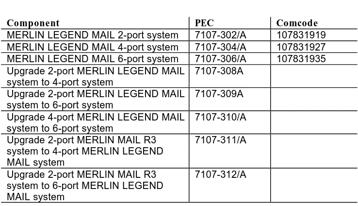
Table A-1 provides the ordering codes for the MERLIN LEGEND MAIL System.
Table A-1. Ordering Codes
Component PEC Comcode
MERLIN LEGEND MAIL 2-port system 7107-302/A 107831919 MERLIN LEGEND MAIL 4-port system 7107-304/A 107831927 MERLIN LEGEND MAIL 6-port system 7107-306/A 107831935 Upgrade 2-port MERLIN LEGEND MAIL
system to 4-port system
7107-308A
Upgrade 2-port MERLIN LEGEND MAIL system to 6-port system
7107-309A
Upgrade 4-port MERLIN LEGEND MAIL system to 6-port system
7107-310/A
Upgrade 2-port MERLIN MAIL R3 system to 4-port MERLIN LEGEND MAIL system
7107-311/A
Upgrade 2-port MERLIN MAIL R3 system to 6-port MERLIN LEGEND MAIL system
Ordering Codes
A-2
Upgrade 4-port MERLIN MAIL R3 system to 6-port MERLIN LEGEND MAIL system
7107-313/A
MERLIN LEGEND MAIL 2-port voice-port card
107831893
MERLIN LEGEND MAIL 4-port voice-port card
107831901
MERLIN LEGEND MAIL Base Module (without disk drive)
107831851
Busying Out/Restoring the
Module
B
Overview
This appendix provides the step-by-step instructions for busying out and restoring the MERLIN LEGEND MAIL module. These instructions are cross-referenced in the procedures provided in Chapter 3 of this guide.
Busying Out the Module
!
CAUTION:Although the system is designed for modules to be removed and replaced without affecting call processing, there is still a possibility that partially removing or inserting a module can cause a cold start of the MERLIN LEGEND system.
Before removing the MERLIN LEGEND MAIL module, you must busy out the slot where the MERLIN LEGEND MAIL module resides. This procedure discontinues service from module.
To busy out the module:
1. At the SPM Main Menu, select Maintenance. 2. At the Maintenance menu, select Slot. 3. Type the slot number and select Enter. 4. Select Busy-Out.
5. Select Yes.
Busying Out/Restoring the Module
B-2
Restoring the Module
After installing the MERLIN LEGEND MAIL module, you must restore it to terminate the busy-out condition.
To restore the module:
1. At the SPM Main Menu, select Maintenance. 2. At the Maintenance menu, select Slot. 3. Type the slot number and select Enter. 4. Select Restore.
5. Select Yes.
Installing/Removing the
Module
C
Overview
This appendix provides the step-by-step instructions for installing and removing the MERLIN LEGEND MAIL module. These instructions are cross-referenced throughout upgrade procedures provided in Chapter 3 of this guide.
!
CAUTION:Installing/Removing the Module
C-2
Installing the Module
To install the MERLIN LEGEND MAIL module:
1. Lower the module onto the rod on the top of the carrier in the appropriate slot.
2. Be sure that the connector on the module mates properly with the connector on the carrier.
3. Swing the module into the slot and firmly push the module into the carrier until it locks into place.
!
CAUTION:To avoid damage, do not force the module. If the module does not insert easily, press the bottom-rear locking tab, remove the module, and inspect the module and carrier for damage or obstruction.
If there is no damage and no obstruction, re-insert the module.
A damaged carrier or module must be replaced.
Removing the Module
To remove the MERLIN LEGEND MAIL module from the MERLIN LEGEND system:
1. Push up firmly on the tab at the bottom rear of the MERLIN LEGEND MAIL module.
2. While holding up the tab, swing the bottom of the module toward you, away from the carrier.
Using the Serial Number
Utility
D
Overview
This appendix provides the step-by-step instructions for re-serializing the disk drive in the MERLIN LEGEND MAIL module. These instructions are cross-referenced in the upgrade procedures provided in Chapter 3 of this guide.
!
WARNING:Using the Serial Number Utility
D-2
Re-Serializing the Disk Drive
To re-serialize the disk drive:
1. At the MERLIN LEGEND MAIL administration menu, type b.
2. Enter the password to shut down the MERLIN LEGEND MAIL system. 3. When prompted, type y to verify that you want to shut down the system. 4. When the MERLIN LEGEND MAIL administration menu reappears, press
the ESC key.
5. At the prompt, type mmsz, press the SPACEBAR once, and then type the six-digit serial number from the bar code label on the top of the disk drive. An example of what you type is:
mmsz 123456
where 123456 is the six-digit serial number from the bar code label on the top of the disk drive.
6. Press the ENTER key.
7. Type mm and then press the ENTER key.
The MERLIN LEGEND MAIL administration menu appears. 8. Type a.
You are prompted to enter the password. 9. Enter the password.
Resetting the System
E
Overview
This appendix provides the instructions for resetting the MERLIN LEGEND MAIL module and RMD.
Resetting the MERLIN LEGEND
MAIL Module
You should perform a system reset when any of the following conditions occur: the MERLIN LEGEND MAIL ports are “locked up” (that is, not answering calls on specific ports).
the MERLIN LEGEND MAIL system answers calls but does not respond in any other way as it should.
the red and green LEDs for a MERLIN LEGEND MAIL port remain on constantly (that is, the LEDs do not blink). This indicates that the port is locked.
None of the LEDs for the MERLIN LEGEND MAIL ports are on.
!
WARNING:This procedure should be performed by qualified technicians only.
Resetting the System
E-2
Resetting the Remote Maintenance
Device
You should reset the RMD only if instructed by the BCS National Service Assistance Center (NSAC). Typically, you will be asked to reset the RMD if the modem does not answer.
!
WARNING:This procedure should be performed by qualified technicians only.
Changing the Far-End
Disconnect Setting and
Adding a 3 db Boost
F
Overview
This appendix provides the step-by-step instructions for changing the far-end disconnect setting and adding a 3 db boost.
NOTE:
These settings should not have to be modified. These settings may only need to be changed if the system is operating in countries other than the United States and Canada.
Changing the Far-End Disconnect
Setting
NOTE:
This setting should not have to be modified. The far-end disconnect setting may only need to be changed if the system is operating in countries other than the United States and Canada.
Switch 1, which is located inside the MERLIN LEGEND MAIL base module, specifies the far-end disconnect signal. If Switch 1 is set to OFF, the far-end disconnect is set to reliable forward disconnect signal (that is, the CO sends a reliable forward disconnect signal). If Switch 1 is set to ON, the far-end
Changing the Far-End Disconnect Setting and Adding a 3 db Boost
F-2
To change the far-end disconnect signal:
!
CAUTION:Before touching leads, connectors, pins, and other components when handling the disk drive, use a properly grounded wrist strap to prevent damage from electrostatic discharge (ESD).
1. Busy out the slot in which the MERLIN LEGEND MAIL module is installed. See Appendix B.
2. Remove the MERLIN LEGEND MAIL module. See Appendix C.
3. Place the MERLIN LEGEND MAIL module on its side with the six-sided cutout (with two metal handles) facing up (Figure F-1).
4. Grasp the two metal handles and gently wriggle the part attached to the handles out of its connectors (Figure F-1). This is the disk drive assembly.
Changing the Far-End Disconnect Setting and Adding a 3 db Boost
Figure F-2 shows the location of the switch for changing the far-end disconnect signal.
Figure F-2. Location of Switches for Far-End Disconnect and 3 db Boost
5. Set Switch 1 to the appropriate setting:
ON: the CO sends busy tone to signal far-end disconnect.
OFF: the CO sends a reliable forward disconnect signal. (This is the default.)
Changing the Far-End Disconnect Setting and Adding a 3 db Boost
F-4
Adding a 3 db Boost
Switch 2, which is located inside the MERLIN LEGEND MAIL base module, specifies whether a 3 db boost is applied. If Switch 2 is set to OFF, a 3 db boost is not applied. If Switch 2 is set to ON, a 3 db boost is applied. By default, Switch 2 is set to OFF.
To add a 3 db boost:
!
CAUTION:Before touching leads, connectors, pins, and other components when handling the disk drive, use a properly grounded wrist strap to prevent damage from electrostatic discharge (ESD).
1. Busy out the slot in which the MERLIN LEGEND MAIL module is installed. See Appendix B.
2. Remove the MERLIN LEGEND MAIL module. See Appendix C.
3. Place the MERLIN LEGEND MAIL module on its side with the six-sided cutout (with two metal handles) facing up (Figure F-1).
4. Grasp the two metal handles and gently wriggle the part attached to the handles out of its connectors (Figure F-1). This is the disk drive assembly. Figure F-2 shows the location of the switch for adding a 3 db boost. 5. Set Switch 2 to the appropriate setting:
ON: a 3 db boost is applied.
OFF: a 3 db boost is not applied. (This is the default.)
Index
A
Acceptance tests overview, 4-1, 4-2
verifying the Remote Maintenance Device, 4-2
B
Base module busy out, B-1 description, 1-3 installation, C-2 remove, C-2 replacing, 3-7 resetting, E-1 restore, B-2 troubleshooting, 4-3 Busy out module, B-1 Busy tone signal, F-1
C
COM port, 1-3
D
db boost, F-4 Disk drive installation, 3-4 overview, 1-3 replacing, 3-4 re-serializing, D-1 troubleshooting, 4-4
E
Expansion carddescription of four-port card, 1-6 description of two-port card, 1-5 installing a four-port card, 3-2 installing a two-port card, 3-2 replacing a four-port card, 3-6 replacing a two-port card, 3-6 troubleshooting, 4-3
F
Far-end disconnect signal overview, F-1
setting, F-1 Four-port system
LED meanings, 1-5 overview, 1-5
port assignments, 1-5
replacing two-port voice-port card, 3-6 troubleshooting, 4-3
upgrading to, 3-2
Four-port voice-port expansion card description, 1-6
replacing, 3-6 troubleshooting, 4-3 upgrading to, 3-2
I
Installation
base module, C-2 preparation, 2-1 procedures, 2-3
L
LEDs meanings, 1-4 overview, 1-3M
MERLIN LEGEND MAIL module busy out, B-1
description, 1-3 installation, C-2 remove, C-2 restore, B-2
MERLIN LEGEND MAIL system advantages, 1-7
components, 1-3 four-port system, 1-5 installation preparation, 2-1 installation procedures, 2-3 ordering codes, A-1 overview, 1-1
replacing a MERLIN MAIL VMS, 3-9 replacing base module, 3-7
Reset button, 1-3 resetting, E-1 six-port system, 1-6 specifications, 1-8 system capacities, 1-1 system compatibility, 1-1 troubleshooting, 4-3 two-port system, 1-4 upgrading, 3-2 MERLIN MAIL VMS
Index
IN-2
Modem
default settings, 1-3 overview, 1-3 Reset button, 1-3 resetting, E-2 verifying, 4-2
O
Ordering codes, A-1
P
Port assignments four-port system, 1-5 six-port system, 1-6 two-port system, 1-4
R
Related documentation, 1-11
Reliable forward disconnect signal, F-1 Remote Maintenance Device
default settings, 1-3 overview, 1-3 Reset button, 1-3 resetting, E-2 verifying, 4-2 Removal
base module, C-2
Re-serializing the disk drive, D-1 Reset buttons, 1-3
Resetting modem, E-2
Remote Maintenance Device, E-2 RMD, E-2
system, E-1 Restore module, B-2 RMD
default settings, 1-3 overview, 1-3 Reset button, 1-3 resetting, E-2 verifying, 4-2 RMD Reset button, 1-3
S
Serial port, 1-3 Six-port system
LED meanings, 1-7 overview, 1-6
port assignments, 1-6
replacing two-port voice-port card, 3-6 troubleshooting, 4-3
upgrading to, 3-2 Specifications, 1-8 System capacities, 1-1 System compatibility, 1-1 System components, 1-3 System module
description, 1-3 System Reset button, 1-3 System specifications, 1-8 System status LED, 1-3
T
Touch tone receivers (TTRs), 1-3 Troubleshooting
overview, 4-1, 4-3 Two-port system
LED meanings, 1-4 overview, 1-4
port assignments, 1-4 troubleshooting, 4-3
Two-port voice-port expansion card description, 1-5 installing, 3-2 replacing, 3-6 troubleshooting, 4-3
U
Upgrades, 3-2V
VM Reset button, 1-3 Voice-port expansion card
007 MLM 6 Internal V
oice Mail Ports
1 Internal Modem Port (5 Unused Ports)
RMD Reset VM1 VM2 VM Reset C O M M VM3 VM4 VM5 VM6 RMD Reset VM1 VM2 VM Reset C O M M VM3 VM4 VM5 VM6
RMD Reset Button
LEDs for Port 1
LEDs for Port 2
System Reset Button
9-Pin Serial Port (Female)
4-Port Expansion Voice-Port Card
LEDs for Port 3
LEDs for Port 4
LEDs for Port 5
LEDs for Port 6
VM3
VM3
RMD Reset
COMM
Status
VM1 VM2
VM Reset
VM3 VM4 VM5 VM6