Dual Nx 56/64 Module
User Manual
901 Explorer Boulevard P.O. Box 140000 Huntsville, AL 35814-4000
Federal Communications Commission (FCC) Radio Frequency Interference Statement
This equipment has been tested and found to comply with the limits for a Class A digital device, pur-suant to Part 15 of the FCC Rules. These limits are designed to provide reasonable protection against harmful interference when the equipment is operated in a commercial environment. This equipment generates, uses, and can radiate radio frequency energy and, if not installed and used in accordance with the instruction manual, may cause harmful interference to radio frequencies. Operation of this equipment in a residential area is likely to cause harmful interference in which case the user will be re-quired to correct the interference at his own expense.
Shielded cables must be used with this unit to ensure compliance with Class A FCC limits.
Warranty and Customer Service
ADTRAN will replace or repair this product within five years from the date of shipment if the product does not meet its published specification, or if it fails while in service. For detailed warranty, repair, and return information, refer to the ADTRAN Equipment Warranty and Repair and Return Policy Proce-dure (see the last page of this manual).
A return material authorization (RMA) is required prior to returning equipment to ADTRAN.
For service, RMA requests, or more information, see the last page of this manual for the toll-free contact number.
Limited Product Warranty
ADTRAN warrants that for five (5) years from the date of shipment to Customer, all products manu-factured by ADTRAN will be free from defects in materials and workmanship. ADTRAN also warrants that products will conform to the applicable specifications and drawings for such products, as con-tained in the Product Manual or in ADTRAN's internal specifications and drawings for such products (which may or may not be reflected in the Product Manual). This warranty only applies if Customer gives ADTRAN written notice of defects during the warranty period. Upon such notice, ADTRAN will, at its option, either repair or replace the defective item. If ADTRAN is unable, in a reasonable time, to repair or replace any equipment to a condition as warranted, Customer is entitled to a full refund of the purchase price upon return of the equipment to ADTRAN. This warranty applies only to the original purchaser and is not transferable without ADTRAN's express written permission. This warranty be-comes null and void if Customer modifies or alters the equipment in any way, other than as specifically authorized by ADTRAN.
EXCEPT FOR THE LIMITED WARRANTY DESCRIBED ABOVE, THE FOREGOING CONSTITUTES THE SOLE AND EXCLUSIVE REMEDY OF THE CUSTOMER AND THE EXCLUSIVE LIABILITY OF ADTRAN AND IS IN LIEU OF ANY AND ALL OTHER WARRANTIES (EXPRESSED OR IMPLIED). ADTRAN SPECIFICALLY DISCLAIMS ALL OTHER WARRANTIES, INCLUDING (WITHOUT LIM-ITATION), ALL WARRANTIES OF MERCHANTABILITY AND FITNESS FOR A PARTICULAR PUR-POSE. SOME STATES DO NOT ALLOW THE EXCLUSION OF IMPLIED WARRANTIES, SO THIS EXCLUSION MAY NOT APPLY TO CUSTOMER.
Table of Contents
List of Figures ... ix
List of Tables... xi
Chapter 1 Introduction ... 1-1
Dual Nx 56/64 Module overview ... 1-1 Features ... 1-1 Interfaces ... 1-1 Module Specifications ... 1-2 DTE Interface... 1-2 Rates ... 1-2 Tests ... 1-2 Test Pattern... 1-2 1s Density Protection ... 1-2 Connectors ... 1-2 Physical Description ... 1-2
Chapter 2 Installation ... 2-1
Unpack and Inspect ... 2-1 ADTRAN Shipments Include ... 2-1 Customer Provides ... 2-1 Installing the Dual Nx 56/64 Module... 2-1 Wiring ... 2-3 Power-Up Testing and Initialization... 2-4
Chapter 3 Operation ... 3-1
Table of Contents
Table of Contents
Mode ... 3-10 Dial ... 3-10 Src Id ... 3-10 Number ... 3-10 Test ... 3-10 Loopback ... 3-10 No Loopback ... 3-10 Local Loopback ... 3-10 Remote Loopback ... 3-10 Loopback Status ... 3-11 511 ... 3-11 Off ... 3-11 On ... 3-11 511 Result ... 3-11 Sync:Y ... 3-11 Sync:N ... 3-11 * ... 3-11 ES ... 3-11 Clr ... 3-11 Inject ... 3-11 ATLAS 550 Features Used with the Dual Nx 56/64 Module ... 3-12 Factory Restore ... 3-12 Run Self Test ... 3-12 Mapping ... 3-12
Appendix A Dial Plan Interface Configuration... A-1
List of Figures
List of Tables
Chapter 1
Introduction
DUAL NX 56/64 MODULE OVERVIEW
The Dual Nx (pronounced “N-by”) 56/64 Module provides two synchro-nous V.35 DTE ports, each of which can operate at any rate that is a multiple of 56 or 64 kbps, up to 2.048 Mbps. The Dual Nx 56/64 Module can be in-stalled in any option slot of the ATLAS 550 chassis.
Features
• Operates using 1 to 32 DS0s on each port
• Includes an elastic store for absorption of rate variations • Uses any port as a timing source for the entire system • Outputs a 50 percent duty-cycle output clock at all rates • Generates and responds to V.54 looping codes
• Generates and checks 511 test patterns • Uses bidirectional loopbacks:
- Port (toward the network) - DTE (toward the DTE)
Interfaces
• Two V.35 Winchester connectors
Chapter 1. Introduction
Module Specifications
DTE Interface
• CCITT V.35 Synchronous
Rates
• 56 kbps to 2.048 Mbps in 56k or 64k steps
Tests
• Local Loopback (Bilateral) • Remote Loopback (V.54) • Self-Test
Test Pattern
• 511 with errored seconds display and error inject capability
1s Density Protection
• Forces 1s to network after one second of consecutive zeros from DTE
Connectors
• Winchester female connectors
Physical Description
The Dual Nx 56/64 Module can plug into any available option slot in the ATLAS 550 chassis (see Figure 1-1).
The module has a label over each connector referring to the port on the card.
Figure 1-1. Dual Nx 56/64 Module The four Option slots (labeled 1 — 4) only accept Option Modules, and the Network Interface slots (labeled Network 1 and Network 2) only accept Network Interface Modules. (See the ATLAS 550 in Figure 2-1 on page 2-2.)
PORT 1
PORT 2 500 Series
Chapter 2
Installation
UNPACK AND INSPECT
Carefully inspect the option module for any shipping damage. If damage is suspected, file a claim immediately with the carrier and contact ADTRAN Technical Support. (See the last page of this manual for information on con-tacting Technical Support.) If possible, keep the original shipping container for use in returning the option module for repair or for verification of dam-age during shipment.
ADTRAN Shipments Include
• The Dual Nx 56/64 Module
• The Dual Nx 56/64 Module User Manual (to be inserted into the appropri-ate section of the ATLAS 550 User Manual)
Customer Provides
• DTE cables
INSTALLING THE DUAL NX 56/64 MODULE
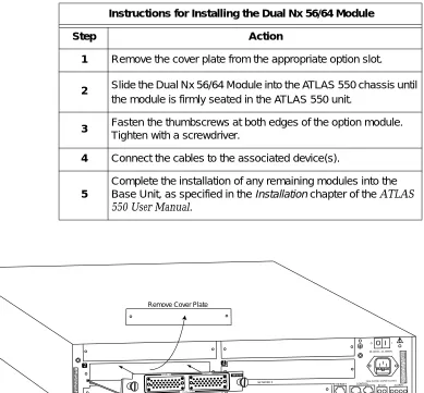
Figure 2-1 on page 2-2 shows the action required for proper placement of the Dual Nx 56/64 Module. To install the option module, perform the steps as listed in the step/action table on page 2-2.
Chapter 2. Installation
Figure 2-1. Installing the Dual Nx 56/64 Module Instructions for Installing the Dual Nx 56/64 Module
Step Action
1 Remove the cover plate from the appropriate option slot.
2 Slide the Dual Nx 56/64 Module into the ATLAS 550 chassis until
the module is firmly seated in the ATLAS 550 unit.
3 Fasten the thumbscrews at both edges of the option module.
Tighten with a screwdriver.
4 Connect the cables to the associated device(s).
5
Complete the installation of any remaining modules into the Base Unit, as specified in theInstallationchapter of theATLAS 550 User Manual.
NETWORK 1 NETWORK 2
2 4
ETHERNET CONTROL
IN OUT
RELAY ALARM
O I
FUSE RATING: 2A/250V SLO-BLO 90-240VAC, 2A, 50/60Hz
NC NO COM GND
A LL EM PT Y SLO TS M U ST BE C OV ER ED W ITH B LA NK P AN ELS C AU T ION : FO R C ON T INU ED P RO TE CT IO N A GA INST R ISK OF F IR E,R EPL AC E ON LY W ITH SA ME T YP EA ND R AT ING O FF US E. MON
Remove Cover Plate
PORT 1 PORT 2
500 Series DUAL V.35
O I
Chapter 2. Installation
WIRING
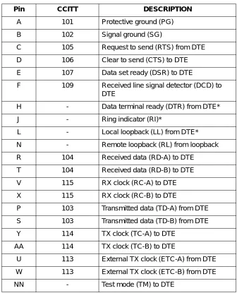
Each port of the Dual Nx 56/64 Module has a V.35 Winchester-style connec-tion as defined in Table 2-1.
*Ignored by Dual Nx 56/64 Module
Table 2-1. V.35 Winchester Pin Connection
Pin CCITT DESCRIPTION
A 101 Protective ground (PG) B 102 Signal ground (SG)
C 105 Request to send (RTS) from DTE D 106 Clear to send (CTS) to DTE E 107 Data set ready (DSR) to DTE
F 109 Received line signal detector (DCD) to DTE
H - Data terminal ready (DTR) from DTE* J - Ring indicator (RI)*
L - Local loopback (LL) from DTE* N - Remote loopback (RL) from loopback R 104 Received data (RD-A) to DTE
T 104 Received data (RD-B) to DTE V 115 RX clock (RC-A) to DTE X 115 RX clock (RC-B) to DTE
P 103 Transmitted data (TD-A) from DTE S 103 Transmitted data (TD-B) from DTE Y 114 TX clock (TC-A) to DTE
AA 114 TX clock (TC-B) to DTE
Chapter 2. Installation
POWER-UP TESTING AND INITIALIZATION
The Dual Nx 56/64 Module executes a self-test during the power-up se-quence, as described in the ATLAS 550 User Manual. Upon power-up, any previously configured setting for the Dual Nx 56/64 Module is automatical-ly restored.
Chapter 3
Operation
OVERVIEW
The Dual Nx 56/64 Module can be configured and controlled as follows: • Terminal menus - used for detailed configuration, status, and
diagnos-tics
• SNMP, used primarily for reporting alarm conditions and system status The terminal menu is accessed using either a VT-100 terminal attached to the ATLAS 550 Base Unit’s control port, or through a Telnet session established through the Base Unit’s Ethernet port. Detailed instructions on the operation of each of the supported management approaches are presented in the
ATLAS 550 User Manual.
The remainder of this section describes the menu items presented when managing the Dual Nx 56/64 Module using the terminal menus.
To edit items in the terminal menus, you must have the appropriate password level. Each menu description in this section indicates the password level required for write and read access. See the section Access Passwords in the ATLAS 550
Chapter 3. Operation
TERMINAL MENU STRUCTURE
The ATLAS 550 uses hierarchical menus to access all features. The topmost menu level leads to submenus which are grouped by functionality. All menu items display in the terminal window.
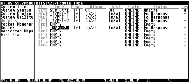
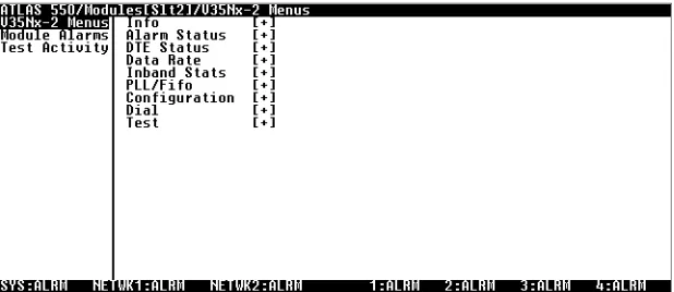
The ATLAS 550 System Controller automatically detects the presence of the Dual Nx 56/64 Module when it is installed in the system. To view the menus for the Dual Nx 56/64 Module via the terminal menu, use the arrow keys to scroll to theMODULESmenu and pressEnterto access the module choices. Figure 3-1 shows theMODULESmenu. (Also see the menu tree in Figure 3-2.)
The following sections describe all the menu options.
Chapter 3. Operation
Slt Info Part Number
Type V35Nx-2 Menus Serial Number
Menu Assembly Revision SLIP
Alarm Module Alarms
(Shortcut to Alarms)
Alarm Status Port PLL
Modules Test Alarms ZERO
State NO EXT CLK
Status DTE Status Prt RTS PKT EP ALM
Rev DTE Status CTS
DTR DSR
Data Rate Port DCD
Rate RI Port
TD Rx Frames RD Tx Frames EC Rx Bytes
Inband Stats Tx Bytes
Reset Stats
PLL/Fifo Port Lock
PLL/Fifo RXE RXF TXE TXF Prt Name
Clk +/- Normal Inverted
Data Normal
Inverted
CTS Forced On
Configuration Normal
Normal
DCD Forced On
DSR Remote RTS
DTR
Zero Inhibit Normal
Inband Forced On
Send Leads Remote RTS
Port Mode
Dial Dial
Source ID Prt No Loopback Number Loopback Local Loopback
LB Status Remote Loopback
Test Activity
Chapter 3. Operation
M
ODULES
M
ENU
S
LT Read security: 5Displays the number of all the available slots in the ATLAS 550 chassis. Slot 0 refers to the ATLAS 550 base unit. This field is read-only.
T
YPE Write security: 3; Read security: 5Displays the type of module actually installed in the slot or the type of module you plan to install in the slot. If a Dual Nx 56/64 Module is installed, theTYPEfield automatically defaults to “V.35 Nx -2” (the Dual Nx 56/64 Module). You can use this field to pre-configure a system before actu-ally installing modules simply by specifying the module that you want to install in each slot.
M
ENU Displays additional status and configuration menus about the selected mod-ule. (To access the submenus for this item, use the arrow keys to scroll to theMENUcolumn for the module you want to edit, and pressEnter.) For detailed information on each submenu item, see the section Dual Nx 56/64 Module
Menu Options on page 3-5.
A
LARM Read security: 5Displays an alarm condition on the Dual Nx 56/64 Module. PressEnterin this field to activate theALARMmenu.
T
EST Read security: 5Activates testing of specific data ports, and controls the activation of loop-backs and the initiation of data test patterns. PressEnterin this field to acti-vate theTESTmenu. See also, Test on page 3-10.
S
TATE Write security: 3; Read security: 5Even though a module is physically installed, it must be markedONLINEfor
TYPEautomatically displays the name of an installed module. If
you want to preconfigure the slot for a different type of module, you must set this field toEMPTYbefore selecting another module
type.
Chapter 3. Operation
S
TATUS Read security: 5This is a read-only field presenting status information on the Dual Nx 56/ 64 Module. The following messages may display:
ONLINE The module is enabled, and is responding to the System Controller’s status
polls. This is the normal response of the system.
NORESPONSE The module is enabled, but is not responding to the System Controller’s
sta-tus polls. This response indicates either a problem in the system or that the module is not installed.
EMPTY The System Controller has not detected the presence of a module in the slot,
nor has a module been manually enabled for this option slot.
OFFLINE The module is installed, but has been taken offline by a user. The module is
still responding to controller polls.
R
EV Read security: 5This is a read-only field that displays the assembly revision of the Dual Nx 56/64 Module.
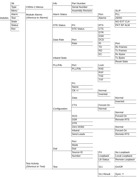
DUAL NX 56/64 MODULE MENU OPTIONS
Figure 3-3 shows the menu options available for the Dual Nx 56/64 Module. The following sections describe these options.
Chapter 3. Operation
I
NFO
Read security: 5TheDUALNX56/64 INFOsubmenu indicates the status of the module.
P
ARTN
UMBER Displays the part number of the module. This field is read-only.S
ERIALN
UMBER Displays the Dual Nx 56/64 Module’s serial number. This field is read-only.A
SSEMBLYR
EVISION Displays assembly revision number. This field is read-only.A
LARM
S
TATUS
Read security: 5This option displays any active alarms. These fields are read-only.
P
ORT Indicates the operating port.A
LARMS Displays the following alarms:SLIP A rate mismatch exists between the DTE clock and the network-side clock (as set by DS0 assignment).
PLL The Nx port is not able to lock onto the clock provided by the network inter-face.
ZERO The DTE is sending an excessive number of consecutive zeroes to the net-work interface.
NO EXT CLK The DTE is not providing an external transmit clock. This alarm displays only if the V.35 Nx port is configured to get its transmit clock from the DTE.
PKT EP ALM A packet endpoint has detected missing or incorrect framing.
DTE S
TATUS
Read security: 5Shows the status of key DTE interface signals. The following signals are monitored (these options are read-only):
Chapter 3. Operation
DTE S
TATUS The following signals are monitored (these options are read-only):RTS Request To Send from DTE
CTS Clear To Send to DTE
DTR Data Terminal Ready from DTE
DSR Data Set Ready to DTE
DCD Data Carrier Detect to DTE
RI Ring Indicate to DTE
TD Transmit Data from the DTE
RD Receive Data toward the DTE
EC External clock present
D
ATA
R
ATE
Read security: 5Displays the data rate at which each Nx port is currently operating. A port’s data rate is determined by the number of DS0s assigned to it and the rate per DS0 associated with the active maps.
I
NBAND
S
TATS
Read security: 5Provides information on the following statistics.
P
ORT Indicates the operating port.R
XF
RAMES Indicates the number of frames received on the operating port since system startup.T
XF
RAMES Indicates the number of frames transmitted form the operating port since system startup.R
XB
YTES Indicates the number of bytes received form the operating port since system startup.Chapter 3. Operation
PLL/F
IFO
Read security: 5Displays the Phase Lock Loop (PLL) and FIFO status.
P
ORT Indicates the operating port.PLL/F
IFO Indicates the state of the port’s Phase Lock Loop (PLL) and FIFO systems.LOCK Phase Lock Loop is locked. This is required in order to transfer data.
RXE Receive Data FIFO Empty
RXF Receive Data FIFO Full
TXE Transmit Data FIFO Empty
TXF Transmit Data FIFO Full
C
ONFIGURATION
TheCONFIGsubmenu configures the Dual Nx 56/64 Module.P
RT Indicates the operating port.N
AME Write security: 3; Read security: 5Allows you to enter a descriptive alpha-numeric name for each port.
C
LK+/-
Write security: 3; Read security: 5Controls the clock used by the Dual Nx 56/64 Module to accept the trans-mit (TX) data from the DTE. This is usually set toNORMAL. If the interface cable is long, causing a phase shift in the data, the clock can be set to
INVERTED. This switches the phase of the clock, which compensates for a
long cable.
D
ATA Write security: 3; Read security: 5Controls the inverting of the DTE data. This inversion can be useful when operating with a high-level data link control (HDLC) protocol (often used as a means to ensure 1s density). Select eitherNORMALorINVERTED.
CTS
Write security: 3; Read security: 5Determines the behavior of the Clear To Send (CTS) signal. If set toNORMAL,
CTS will follow the value of Request To Send (RTS). If set toFORCEDON,
CTS will always be asserted. (See Table 3-1 for normal operation of this sig-nal.)
Chapter 3. Operation
550 User Manual for exact conditions.) If set toFORCEDON, DCD will
always be asserted. If set toREMOTERTS, the value of DCD will track the value of the remote unit’s RTS signal. Note that this feature requires the Inband control channel to beENABLED. (See Table 3-1 for normal operation
of this signal.)
DSR
Write security: 3; Read security: 5Determines the behavior of the Data Set Ready (DSR) signal. If set toNOR
-MAL, DSR will generally be asserted when the interface is capable of passing
data. If set toFORCEDON, DSR will always be asserted. If set toREMOTE
DTR, the value of DSR will track the value of the remote unit’s DTR signal. Note that this feature requires the Inband control channel to beENABLED.
(See Table 3-1 for normal operation of this signal).
DTR
Write security: 3; Read security: 5Determines whether the ATLAS 550 treats a connection as permanent
(IGNORE) or connects only when Data Terminal Ready (DTR) is active (CON
-NECTONDTR). Select eitherIGNOREorCONNECT ONDTR.
(Z
EROI
NHIBIT)
Write security: 3; Read security: 5When the port detects an uninterrupted string of 0s being transmitted for more than one second, setting this parameter toONwill cause the ATLAS 550 to send 1s toward the network.
I
NBAND Creates an inband management channel by robbing 8 kbps bandwidth from the port’s allocated bandwidth. This channel can be used for management for ADTRAN products that are not co-located with the ATLAS. Consult the manual for ADTRAN T1 equipment for details on using this feature.S
ENDL
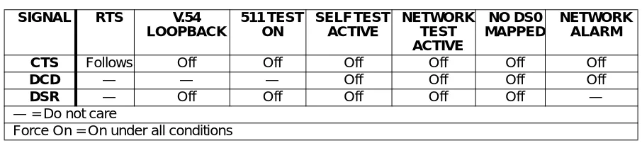
EADS Sends the state of the DTE leads to the remote unit whenever any of the leads change state. If any leads on the remote unit are set to track a remote signal, this option must be enabled. The DTE lead states are conveyed using the In-band control channel, which must be enabled.Table 3-1. Normal Mode Operation(conditions which cause the port control signal to be deactivated)
SIGNAL RTS V.54
LOOPBACK 511 TEST ON SELF TEST ACTIVE NETWORK TEST ACTIVE NO DS0 MAPPED NETWORK ALARM
CTS Follows Off Off Off Off Off Off
DCD — — — Off Off Off Off
DSR — Off Off Off Off Off —
— = Do not care
Chapter 3. Operation
D
IAL
Read security: 5Dials an Nx port that is configured to ignore DTR.
P
RT Indicates the operating port.M
ODE Indicates the dialing mode:PERSISTENTorONETIME.PERSISTENTdialing specifies that the Nx endpoint should redial whenever the call is cleared or if the call fails.ONETIMEdialing specifies that the Nx endpoint should at-tempt the call only once. If the call fails or is cleared, the call is not redialed.D
IAL If the Nx module is set toDTR/IGNORE(see DTR on page 3-10), the user can manually place a call,<CONNECT>, and manually disconnect a call,<CLEARATTEMPT>, via this menu item.
S
RCI
D Indicates theSOURCEIDof the number to be dialed. Configure this field in the NxINTERFACECONFIGURATIONsection of theDIALPLAN.N
UMBER Indicates the number to be dialed. Configure this field in the NxINTERFACECONFIGURATIONsection of theDIALPLAN.
T
EST
L
OOPBACK Write security: 4; Read security: 5Controls the activation and deactivation of loopbacks.
NOLOOPBACK The loop is deactivated.
LOCAL
LOOPBACK
The Nx port activates both a local loopback (back toward the DTE) and a port loopback when invoked.
REMOTE
LOOPBACK
Chapter 3. Operation
L
OOPBACKS
TATUS Read security: 5This read-only option indicates a port’s current loopback status by display-ing any of the followdisplay-ing status messages:
• No loopback active • Looping up remote unit • Remote unit looped back • Looping down remote unit • Remote loop-up failed
• Port looped from remote source • Port loopback active
511
Write security: 4; Read security: 5Controls the activation of the 511 test pattern generator and detector.
OFF Turns off the 511 test pattern generator and detector.
ON Turns on the 511 test pattern generator and detector.
511 R
ESULT Read security: 5Displays the results of the 511 test. This option is read-only. Clear these results by pressingEnterwhenCLRis selected.
SYNC:Y 511 Pattern Sync detected.
SYNC:N 511 Pattern Sync not detected.
* 511 Pattern Sync lost.
ES Detects the current errored seconds (ES); that is, the number of seconds (after Pattern Sync) that have contained at least one error.
C
LR Write security: 4; Read security: 5 Clears test results for the selected port.Chapter 3. Operation
ATLAS 550 FEATURES USED WITH THE DUAL NX 56/64 MODULE
In addition to the Dual Nx 56/64 Module menu items, two additional ATLAS 550 menu items may be operated in conjunction with the Dual Nx 56/64 Module. These areFACTORYRESTOREandRUNSELFTEST.
F
ACTORY
R
ESTORE
FACTORYRESTORErestores the factory-installed default setting for all Dual
Nx 56/64 Module parameters. WhenFACTORYRESTOREdisplays, place the
cursor on it and pressEnter. The unit is restored to preset factory defaults and returns to the main ATLAS 550 menu.
R
UN
S
ELF
T
EST
RUNSELFTEST, a submenu of the ATLAS 550 main menu itemTEST, exe-cutes the ATLAS 550 internal test for the Dual Nx 56/64 Module. For addi-tional information onSELFTESTsee the ATLAS 550 User Manual.MAPPING
DS0s are used as defined in theDEDICATEDMAPor in theDIALPLANfor
Appendix A
Dial Plan Interface Configuration
DIAL PLAN OVERVIEW
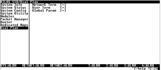
TheDIALPLANmenu sets configuration parameters for each switched end-point. These parameters will vary by the type of port selected. The following section describes the configuration options available for the Dual Nx 56/64 option module. To access these options, selectDIALPLANfrom the top level menu.
Figure A-1. Dial Plan Menus
Dual Nx 56/64 Option Module Interface Configuration
This section describes theUSERTERMINATIONconfiguration settings for the
Dual Nx 56/64 Module when using theDIALPLANmenus.
The Dual Nx 56/64 can only serve as aUSERTERMINATION
Appendix A. Dial Plan Interface Configuration
Dual Nx 56/64 Option Module (User Termination)
When you are working in theUSERTERMsection of theDIALPLANmenu, and theSLTis defined asV35NX-2, the following Interface Configuration options are available:
PORTSAVAILABLE Indicates which of the two ports of the Dual Nx 56/64 Module have already
been defined either in another switched endpoint (indicated byS) or in a
DEDICATEDMAP(indicated byN). This field is read-only.
NUMBER OFPORTS Defines to the ATLAS 550 how many of the ports could be used to answer
calls to the number(s) defined in theINCOMINGACCEPTCALLLIST. You can enter numbers 1 or 2. The ports are contiguous beginning with the port number selected and the number of ports.
Example: If the port selected (as a part of theSLOT/PORTselection) is 2, and the number of ports selected here was 1, then only port 2 would be enabled to receive calls to the numbers listed under theINCOMINGCALLACCEPT
LIST.
NUMBER TODIAL Indicates the number to be dialed.
CALLTYPE Indicates whether the call will be64Kor56Kdata rate:56Kis intended for use in applications where interoperability withSWITCHED56service is desired.64Kis the default call type.
DIALCALLAS Indicates how the call will be handled over the network:DIGITAL,VOICE, or
AUDIO.
DIGITAL
Requests a 56 kbps data circuit that is rate-adapted to 56 kbps or an unre-stricted 64 kbps data circuit.
VOICE
Requests a Mu-law/A-law speech circuit as the bearer capability for outgo-ing calls. UseVOICEwith an ISDN line configured for voice service. In some areas, voice service costs less than data service. AVOICEcall type does not guarantee an end-to-end digital connection with some local and long dis-tance carriers.
AUDIO
Appendix A. Dial Plan Interface Configuration
SOURCEID The Source ID field is used to simplify the creation of a Dial Plan in
applica-tions where the criterion for switching calls to a certain endpoint is a func-tion of which endpoint originated the call.
• Default value = 0. The default ID for all endpoints is 0 and for all accept numbers is 0. With default values, all calls are routed based only on di-aled number.
• Multiple endpoints can have the same Source ID.
• When creating the Call Accept list, specify a Source ID(s) as well as a di-aled number or range of didi-aled numbers to accept.
Index
A
ADTRAN shipments include 2-1 ATLAS menus and submenus
FACTORYRESTORE3-12
MODULES3-4
ALARM3-4 MENU3-4 REV3-5
SLT3-4 STATE3-4
STATUS3-5
EMPTY3-5
NORESPONSE3-5
OFFLINE3-5
ONLINE3-5
TEST3-4 TYPE3-4 RUNSELFTEST3-12
See also DIALPLAN.
C
customer service iii
D
description of product 1-2 DIALPLAN
INTERFACECONFIGURATION(USERTERMINA
-TION) A-1, A-2 CALLTYPEA-2
DIALCALLASA-2
DIALCALLAS(AUDIO) A-2
DIALCALLAS(DIGITAL) A-2
DIALCALLAS(VOICE) A-2
NUMBER OFPORTSA-2
NUMBER TODIALA-2
overview 1-1
physical description 1-2 specifications 1-2
Dual Nx 56/64 menus and submenus
ALARMSTATUS3-6
ALARMS3-6
NOEXTCLOCK3-6 PKT EP ALM 3-6 PLL 3-6
SLIP3-6 ZERO3-6 PORT3-6
CONFIGURATION3-8
(ZEROINHIBIT) 3-9
CLK+/- 3-8 CTS 3-8 DATA3-8 DCD 3-8 DSR 3-9 DTR 3-9
INBAND3-9
NAME3-8
PRT3-8
SENDLEADS3-9
DATARATE3-7 DIAL3-10
DIAL3-10 MODE3-10
NUMBER3-10
PRT3-10 SRCID3-10 DTE STATUS
Index
PORT3-7 RESETSTATS3-7 RXBYTES3-7
RXFRAMES3-7
TXBYTES3-7
TXFRAMES3-7
INFO3-6
ASSEMBLYREVISION3-6
PARTNUMBER3-6
SERIALNUMBER3-6
PLL/FIFO3-8 LOCK3-8 PORT3-8 RXE 3-8 RXF 3-8 TXE 3-8 TXF 3-8 TEST3-10
511 3-11 OFF3-11 ON3-11 511 RESULT3-11
* 3-11 ES 3-11 SYNC:N 3-11 SYNC:Y 3-11 CLR3-11
INJECT3-11
LOOPBACK3-10
LOCALLOOPBACK3-10
NOLOOPBACK3-10
REMOTELOOPBACK3-10
LOOPBACKSTATUS3-11
F
features 1-1
I
initialization 2-4
inspecting the shipment 2-1 installation 2-1
installing the module 2-1 interfaces 1-1
L
limited product warranty iv
M
mapping 3-12
marking module online 3-4 menu structure 3-2
O
operation 3-1 overview 1-1
P
physical description 1-2 power-up testing 2-4
R
returning the module 2-1 RMA requests iii
Product Support Information
Pre-sales Inquiries and Applications Support
Please contact your local distributor, ADTRAN Applications Engineering, or ADTRAN Sales:
Post-Sale Support
Please contact your local distributor first. If your local distributor cannot help, please contact ADTRAN Technical Support and have the unit serial number available.
Repair and Return
If ADTRAN Technical Support determines that a repair is needed, Technical Support will coordinate with the Custom and Product Service (CAPS) department to issue an RMA number. For information regarding equipment currently in house or possible fees associated with repair, contact CAPS directly at the following number:
Identify the RMA number clearly on the package (below address), and return to the following address:
ADTRAN Customer and Product Service 6767 Old Madison Pike
Building #6 Suite 690 Huntsville, Alabama 35807
RMA # _____________
Applications Engineering (800) 615-1176
Sales (800) 827-0807
Technical Support (888) 4ADTRAN