Hardware Installation Guide
4200990L1 NetVanta 5305 Chassis
4200990L2 NetVanta 5305 Chassis with Enhanced Feature Pack 1200832L1 NetVanta 5305 T3 Wide Module
1200934L1 NetVanta HSSI Wide Module 1200843L1 NetVanta Octal T1/E1 Wide Module 1200840L1 NetVanta 5305 AC Power Supply
4200368L3 NetVanta 5305 Enhanced Feature Pack (VPN Upgrade)
Trademarks
Any brand names and product names included in this manual are trademarks, registered trademarks, or trade names of their respective holders.
To the Holder of this Manual
The contents of this manual are current as of the date of publication. ADTRAN reserves the right to change the contents without prior notice.
In no event will ADTRAN be liable for any special, incidental, or consequential damages or for commercial losses even if ADTRAN has been advised thereof as a result of issue of this publication.
Conventions
Safety Instructions
When using your communications equipment, please follow these basic safety precautions to reduce the risk of fire, electrical shock, or personal injury:
1. Do not use this product near water such as a bathtub, wash bowl, kitchen sink, laundry tub, in a wet basement, or near a swimming pool.
2. Avoid using a telephone (other than a cordless-type) during an electrical storm. There is a remote risk of shock from lightning.
3. Do not use a telephone to report a gas leak in the vicinity of the leak.
4. Use only the power cord, power supply, and/or batteries indicated in the manual. Do not dispose of batteries in a fire. They may explode. Check with local codes for special disposal instructions.
Save These Important Safety Instructions
Notes provide additional useful information.Cautions signify information that could prevent service interruption.
Affidavit Requirements for Connection to Digital Services
• An affidavit is required to be given to the telephone company whenever digital terminal equipment (DTE) without encoded analog content and billing protection is used to transmit digital signals containing encoded analog content intended for eventual conversion into voiceband analog signals and transmitted on the network.
• The affidavit shall affirm that either no encoded analog content or billing information is being transmitted or that the output of the device meets Part 68 encoded analog content or billing protection specifications.
• The end user/customer will be responsible for filing an affidavit with the local exchange carrier when connecting unprotected customer premise equipment (CPE) to 1.544 Mbps or subrate digital services.
Affidavit for Connection of Customer Premises Equipment
to 1.544 Mbps and/or Subrate Digital Services
For the work to be performed in the certified territory of ___________________ (telco name)
State of ________________
County of ________________
I, _______________________ (name), ____________________________________ (business address),
____________________ (telephone number) being duly sworn, state:
I have responsibility for the operation and maintenance of the terminal equipment to be connected to 1.544 Mbps and/or ________ subrate digital services. The terminal equipment to be connected complies with Part 68 of the FCC rules except for the encoded analog content and billing protection specifications. With respect to encoded analog content and billing protection:
( ) I attest that all operations associated with the establishment, maintenance, and adjustment of the digital CPE with respect to analog content and encoded billing protection information continuously complies with Part 68 of the FCC Rules and Regulations.
( ) The digital CPE does not transmit digital signals containing encoded analog content or billing information which is intended to be decoded within the telecommunications network.
( ) The encoded analog content and billing protection is factory set and is not under the control of the customer. I attest that the operator(s)/maintainer(s) of the digital CPE responsible for the establishment, maintenance, and adjustment of the encoded analog content and billing information has (have) been trained to perform these functions by successfully having completed one of the following (check appropriate statements):
( ) A. A training course provided by the manufacturer/grantee of the equipment used to encode analog signals; or ( ) B. A training course provided by the customer or authorized representative, using training materials and instructions
provided by the manufacturer/grantee of the equipment used to encode analog signals; or
( ) C. An independent training course (e.g., trade school or technical institution) recognized by the manufacturer/grantee of the equipment used to encode analog signals; or
( ) D. In lieu of the preceding training requirements, the operator(s)/maintainer(s) is (are) under the control of a supervisor trained in accordance with _________ (circle one) above.
I agree to provide ______________________ (telco’s name) with proper documentation to demonstrate compliance with the information as provided in the preceding paragraph, if so requested.
_________________________________Signature _________________________________Title _________________________________ Date
Transcribed and sworn to before me
This ________ day of _______________, _______ _________________________________
Notary Public
FCC regulations require that the following information be provided in this manual:
1. This equipment complies with Part 68 of FCC rules and requirements adopted by ACTA Each registered interface has a label that contains, among other information, a product identifier in the format US:AAAEQ##TXXXX. If requested, provide this information to the telephone company. 2. If this equipment causes harm to the telephone network, the telephone company may temporarily
discontinue service. If possible, advance notification is given; otherwise, notification is given as soon as possible. The telephone company will advise the customer of the right to file a complaint with the FCC.
3. The telephone company may make changes in its facilities, equipment, operations, or procedures that could affect the proper operation of this equipment. Advance notification and the opportunity to maintain uninterrupted service are given.
4. If experiencing difficulty with this equipment, please contact ADTRAN for repair and warranty information. The telephone company may require this equipment to be disconnected from the network until the problem is corrected or it is certain the equipment is not malfunctioning. 5. This unit contains no user-serviceable parts.
6. This equipment is designed to connect to the telephone network or premises wiring using an FCC compatible modular jack, which is compliant with Part 68 and requirements adopted by ACTA. 7. The following information may be required when applying to the local telephone company for
leased line facilities:
8. The REN is useful in determining the quantity of devices you may connect to your telephone line and still have all of those devices ring when your number is called. In most areas, the sum of the RENs of all devices should not exceed five. To be certain of the number of devices you may connect to your line as determined by the REN, call your telephone company to determine the maximum REN for your calling area.
9. This equipment may not be used on coin service provided by the telephone company. Connection to party lines is subject to state tariffs. Contact your state public utility commission or corporation
Part Number
Registration
Number Service Type REN/SOC FIC USOC
1200843L1 US: HDCDENAN1200843L1
1.544 Mbps - SF
1.544 Mbps - SF and B8ZS 1.544 Mbps - ESF
1.544 Mbps - ESF and B8ZS
Federal Communications Commission Radio Frequency Interference Statement
This equipment has been tested and found to comply with the limits for a Class A digital device, pursuant to Part 15 of the FCC Rules. These limits are designed to provide reasonable protection against harmful interference when the equipment is operated in a commercial environment. This equipment generates, uses, and can radiate radio frequency energy and, if not installed and used in accordance with the
instruction manual, may cause harmful interference to radio frequencies. Operation of this equipment in a residential area is likely to cause harmful interference in which case the user will be required to correct the interference at his own expense.
Industry Canada Compliance Information
Notice: The Industry Canada label applied to the product (identified by the Industry Canada logo or the “IC:” in front of the certification/registration number) signifies that the Industry Canada technical specifications were met.
Notice: The Ringer Equivalence Number (REN) for this terminal equipment is supplied in the
documentation or on the product labeling/markings. The REN assigned to each terminal device indicates the maximum number of terminals that can be connected to a telephone interface. The termination on an interface may consist of any combination of devices subject only to the requirement that the sum of the RENs of all the devices should not exceed five (5).
Canadian Emissions Requirements
This digital apparatus does not exceed the Class A limits for radio noise emissions from digital apparatus as set out in the interference-causing equipment standard entitled “Digital Apparatus,” ICES-003 of the Department of Communications.
Product Warranty
ADTRAN will replace or repair this product within the warranty period if it does not meet its published specifications or fails while in service. Warranty information can be found at www.adtran.com/warranty.
Product Registration
Registering your product helps ensure complete customer satisfaction. Please take time to register your products on line at www.adtran.com. Click Service and Support on the top of the page, and then click
Product Registration under Support.
Customer Service, Product Support Information, and Training
ADTRAN will replace or repair this product within the warranty period if it does not meet its published specifications or fails while in service. Warranty information can be found at www.adtran.com/warranty.
A return material authorization (RMA) is required prior to returning equipment to ADTRAN. For service, RMA requests, training, or more information, use the contact information given below.
Repair and Return
If you determine that a repair is needed, please contact our Customer and Product Service (CAPS) department to have an RMA number issued. CAPS should also be contacted to obtain information regarding equipment currently in house or possible fees associated with repair.
Identify the RMA number clearly on the package (below address), and return to the following address:
Pre-Sales Inquiries and Applications Support
Your reseller should serve as the first point of contact for support. If additional pre-sales support is needed, the ADTRAN Support web site provides a variety of support services such as a searchable knowledge base, latest product documentation, application briefs, case studies, and a link to submit a question to an Applications Engineer. All of this, and more, is available at:
When needed, further pre-sales assistance is available by calling our Applications Engineering Department.
CaPS Department (256) 963-8722
ADTRAN Customer and Product Service 901 Explorer Blvd. (East Tower)
Huntsville, Alabama 35806
RMA # _____________
http://support.adtran.com
Post-Sale Support
Your reseller should serve as the first point of contact for support. If additional support is needed, the ADTRAN Support web site provides a variety of support services such as a searchable knowledge base, updated firmware releases, latest product documentation, service request ticket generation and
trouble-shooting tools. All of this, and more, is available at:
When needed, further post-sales assistance is available by calling our Technical Support Center. Please have your unit serial number available when you call.
Installation and Maintenance Support
The ADTRAN Custom Extended Services (ACES) program offers multiple types and levels of installation and maintenance services which allow you to choose the kind of assistance you need. This support is available at:
For questions, call the ACES Help Desk.
Training
The Enterprise Network (EN) Technical Training Department offers training on our most popular products. These courses include overviews on product features and functions while covering applications of
ADTRAN's product lines. ADTRAN provides a variety of training options, including customized training and courses taught at our facilities or at your site. For more information about training, please contact your Territory Manager or the Enterprise Training Coordinator.
http://support.adtran.com
Technical Support (888) 4ADTRAN
http://www.adtran.com/aces
ACES Help Desk (888) 874-ACES (2237)
Training Phone (800) 615-1176, ext. 7500 Training Fax (256) 963-6700
TABLE OF CONTENTS
1. Introduction to the NetVanta 5305 Solution ... 13
Features and Specifications ... 13
Unpack and Inspect the System ... 14
Contents of ADTRAN Shipments ... 14
2. Product Overview ... 15
Reviewing the Chassis Front Panel Design ... 15
Front Panel LEDs ... 16
Reviewing the Chassis Rear Panel Design ... 17
Rear Panel Interfaces ... 17
3. Option Modules ... 18
NetVanta 5305 Controller ... 18
NetVanta 5305 T3 Wide Module (P/N 1200832L1) ... 19
NetVanta HSSI Wide Module (P/N 1200934L1) ... 20
NetVanta Octal T1/E1 Wide Module (P/N 1200843L1) ... 21
4. Unit Installation ... 22
Tools Required ... 22
Mounting Options ... 23
Rack Mounting NetVanta 5305 ... 23
Installing Modules ... 24
Grounding Instructions ... 24
AC Power ... 24
Supplying Power to the Unit ... 25
AC-Powered Systems ... 25
Redundant Power Supply (Optional) ... 25
Installing the NetVanta VPN Accelerator Card (4200368L3) ... 25
Appendix A. Pin Assignments ... 27
Controller Pinouts ... 27
Connector Pinouts ... 28
Figures
Figure 1. NetVanta 5305 Front Panel Layout ... 15
Figure 2. NetVanta 5305 Rear Panel ... 17
Figure 3. NetVanta 5305 Controller Module ... 18
Figure 4. NetVanta 5305 T3 Wide Module ... 19
Figure 5. NetVanta HSSI Wide Module ... 20
Figure 6. NetVanta Octal T1/E1 Wide Module ... 21
Figure 7. Rack Mounting the NetVanta 5305 ... 23
Figure 8. VPN Card Installation ... 26
Tables
Table 1.
NetVanta 5305 LEDs... 16
Table A. 10/100BaseT Ethernet Port Pinout ... 27
Table B. CONSOLE Port (DCE) Pinout ... 27
Table C. T1 1/1 Network (RJ-48C) Connection Pinout ... 28
Table D. T3 Wide Module/T3 Interface (BNC) ... 28
1.
INTRODUCTION TO THE NETVANTA 5305 SOLUTION
The NetVanta 5305 is a modular multi-service access router designed for corporate office connectivity over frame relay or point-to-point (PPP) networks. The NetVanta 5305 has six modular slots for customizing solutions and runs with the ADTRAN Operating System (ADTRAN OS).
The NetVanta 5305 family includes the NetVanta 5305 Chassis, AC power supply, and system controller. Currently, the NetVanta 5305 family offers an unchannelized T3/FT3 Wide Module for network and data applications, the HSSI Wide Module, the Octal T1 Wide Module, and two integrated auto-sensing
10/100BaseT Ethernet ports for local area network connectivity. For VPN applications using the NetVanta 5305, the enhanced feature pack provides encryption/decryption and security acceleration services. Refer to page 25 for VPN card installation information.
Features and Specifications
The NetVanta 5305 has the following features:
• Unchannelized T3 network access via the T3 Wide Module • Integrated IP router with bridging
• WAN Protocol: Frame Relay, PPP • Stateful inspection firewall standard
• RIP Versions 1 and 2, and OSPF routing protocols • Two integrated 10/100BaseT Ethernet ports (RJ-48C) • Optional VPN accelerator card
• Network Address Translation - 1:1, 1:many (NAPT), and Reverse NAT • ADTRAN Operating System Command Line Interface (CLI)
• DHCP client, server, and relay support • Front panel LEDs
• Redundant power supply option
• 3U rack mountable in a 19" and 23” racks • Six modular slots
• Chassis dimensions: 5.25" H, 11.625" D, 17" W • AC power information: 85-250VAC 50/60Hz
This hardware installation guide describes the NetVanta 5305 unit, details basic functionality, gives
Unpack and Inspect the System
Each NetVanta 5305 unit is shipped in its own cardboard shipping carton. Open the carton carefully, and avoid deep penetration into the carton with sharp objects.
After unpacking the unit, inspect it for possible shipping damage. If the equipment has been damaged in transit, immediately file a claim with the carrier and contact ADTRAN Customer Service (see Product Warranty, on page 9).
Contents of ADTRAN Shipments
NetVanta 5305 AC System
Shipments of the NetVanta 5305 include the following items: • NetVanta 5305
• NetVanta 5305 CD • Warranty Card
• IEC 3-prong power cord • 19” Rack Mount Kit
NetVanta 5305 T3 Wide Module
Shipments of the T3 Wide Module include the following items: • T3 Wide Module
• T3 cable
• Quick Start Guide
NetVanta HSSI Wide Module
Shipments of the HSSI Wide Module include the following items: • HSSI Wide Module
• Quick Start Guide
NetVanta Octal T1 Wide Module
2.
PRODUCT OVERVIEW
Reviewing the Chassis Front Panel Design
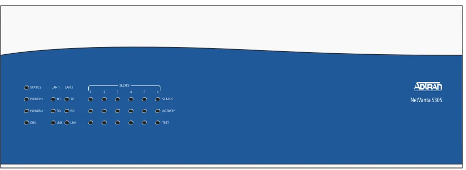
Figure 1 shows the NetVanta 5305 front panel.
Front Panel LEDs
Table 1 describes the front panel LEDs in order as located on the chassis from left to right.
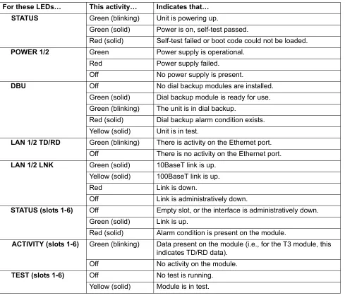
Table 1. NetVanta 5305 LEDs
For these LEDs… This activity… Indicates that…
STATUS Green (blinking) Unit is powering up.
Green (solid) Power is on, self-test passed.
Red (solid) Self-test failed or boot code could not be loaded.
POWER 1/2 Green Power supply is operational.
Red Power supply failed.
Off No power supply is present.
DBU Off No dial backup modules are installed.
Green (solid) Dial backup module is ready for use. Green (blinking) The unit is in dial backup.
Red (solid) Dial backup alarm condition exists. Yellow (solid) Unit is in test.
LAN 1/2 TD/RD Green (blinking) There is activity on the Ethernet port.
Off There is no activity on the Ethernet port.
LAN 1/2 LNK Green (solid) 10BaseT link is up.
Yellow (solid) 100BaseT link is up.
Red Link is down.
Off Link is administratively down.
STATUS (slots 1-6) Off Empty slot, or the interface is administratively down. Green (solid) Link is up.
Red (solid) Alarm condition is present on the module.
ACTIVITY (slots 1-6) Green (blinking) Data present on the module (i.e., for the T3 module, this indicates TD/RD data).
Off No activity on the module.
TEST (slots 1-6) Off No test is running.
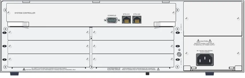
Reviewing the Chassis Rear Panel Design
Figure 2 shows the NetVanta 5305 rear panel. Pinouts for the connectors are given in Appendix A.
Figure 2. NetVanta 5305 Rear Panel
Rear Panel Interfaces
CONSOLE Port
The CONSOLEport, a DB-9 interface located on the rear panel, connects to a computer or modem and provides the following functions:
• Accepts electrical EIA-232 input from a PC or modem for controlling the NetVanta 5305. • Operates at rates ranging from 9.6 kbps to 115.2 kbps.
• Acts an input for either VT100 or PC control.
LAN Interfaces (ETH 0/1, ETH 0/2)
The NetVanta 5305 provides two RJ-48C connectors on the rear panel Controller module for routing data traffic and for local management access. See Table A on page 27 for the 10/100BaseT Ethernet interface pinout. The 10/100BaseT Ethernet ports provide the following:
• Auto-sensing
• Primary data port service • Secondary DMZ port service • Local management access
1
2
3
REMOVE POWER CORD PRIOR TO REMOVAL OF POWER SUPPLY
CAUTION:
3.
OPTION MODULES
The NetVanta 5305 family currently offers three option modules to meet networking requirements:
•
NetVanta 5305 T3 Wide Module (see page 19)
•
NetVanta HSSI Wide Module (see page 20)
•
NetVanta T1/E1 Wide Module (see page 21)
The following pages describe each module, providing individual card specifications and features. Refer to Appendix A for pinout information. The Installing Modules section on page 24 provides information on module installation.
NetVanta 5305 Controller
The NetVanta 5305 uses a central Controller card to provide configuration for the system using the ADTRAN AOS. The NetVanta 5305 Controller (shown in Figure 3) provides control interfaces for the NetVanta 5305 system including a CONSOLE port (DB-9) and two Ethernet interfaces (RJ-48). Refer to Table B on page 27 for the CONSOLE connector pinout, and to Table A on page 27 for the Ethernet connector pinout. A Controller module is required for all NetVanta 5305 systems.
Figure 3. NetVanta 5305 Controller Module
Features and Specifications Interfaces
• Console: EIA-232 (DB-9 female) for access to command line interface and monitoring • Ethernet: Two 10/100BaseT interface (RJ-48) for connection to the local area network.
Agency Approvals
• FCC Part 15, Class A
NetVanta 5305 T3 Wide Module (P/N 1200832L1)
The NetVanta 5305 T3 Wide Module (shown in Figure 4) provides a T3 interface with a dual BNC for the NetVanta 5305. The T3 connection provides a full unchannelized T3 interface that provides a connection to the Wide Area Network. Up to two T3 Wide Modules may be used simultaneously in the NetVanta 5305 chassis. The T3 Wide Module may be installed in any slot (1-6). Table D on page 28 gives the pinout for this module.
Figure 4. NetVanta 5305 T3 Wide Module
Features and Specifications Interface
• DS-3: electrical (coax) interface
Electrical (coax) interface
• Line Rate: 44.736 Mbps
• Line Code: B3ZS (Bipolar Three Zero Substitution)
• Framing: M13 or C-bit
• Connector: Dual BNC (1 receive, 1 transmit)
Agency Approvals
• FCC Part 15, Class A
• UL 60950/CSA-C22.2 No. 60950 • EN 60950/IEC 60950
• AS/NZS 60950 • EN 55022 • EN 55024
Environmental
• Operating Temperature: 0°C to 50°C • Storage Temperature: -20°C to 70°C
NetVanta HSSI Wide Module (P/N 1200934L1)
The NetVanta 5305 HSSI Wide Module (shown in Figure 5) provides a HSSI interface for the NetVanta 5305. Up to two HSSI Wide Modules may be used simultaneously in the NetVanta 5305 chassis. The HSSI Wide Module may be installed in any slot (1-6). Table E on page 29 gives the pinout for this module.
Figure 5. NetVanta HSSI Wide Module
Features and Specifications Interface
• 50 pin SCSI-II female connector
• Line Rate: 0-52 Mbps
• Signal Type: Electrically balanced with Non Return to Zero encoding
Agency Approvals
• FCC Part 15, Class A
• UL 60950/CSA-C22.2 No. 60950 • EN 60950
• IEC 60950 • AS/NZS 60950 • EN 55022 • EN 54024
Environmental
• Operating Temperature: 0°C to 50°C • Storage Temperature: -20°C to 70°C
NetVanta Octal T1/E1 Wide Module (P/N 1200843L1)
The NetVanta Octal T1/E1 Wide Module (shown in Figure 6) provides eight T1 interfaces with RJ-48C wire connections. These interfaces can be used independently or as aggregate bandwidth using Multi-Link PPP protocol. Up to six T1/E1 Wide Modules may be used simultaneously in the NetVanta 5305 chassis. The T1/E1 Wide Module may be installed in any slot (1-6). Table C on page 28 gives the pinout for this module.
Figure 6. NetVanta Octal T1/E1 Wide Module
Features and Specifications Interface
• RJ-48C
• Line Rate: 1.544 Mbps +/- 75 bps • Capacity: Eight T1 circuits
• Line Codes: AMI or B8ZS
• Framing: D4 (SF) or ESF
• Line Build-Out: 0,- 7.5, -15, -22.5 dB • Input Signal: 0 to -36 dB (DS-1)
Support for Nx64 on all T1 interfaces (1-8) Support for Nx56 on T1 interfaces (1-7)
Agency Approvals
• FCC Part 15/Class A
• UL 60950/CSA C22.2 No. 60950 • FCC Part 68/ACTA
• Industry Canada
Environmental
• Operating Temperature: 0°C to 50°C • Storage Temperature: -20°C to 70°C
4.
UNIT INSTALLATION
The instructions and guidelines provided in this section cover hardware installation topics such as rack mounting the unit and installing option cards. These instructions are presented as follows:
• Rack Mounting NetVanta 5305 section on page 23 • Installing Modules section on page 24
• Supplying Power to the Unit section on page 25
• Installing the NetVanta VPN Accelerator Card (4200368L3) section on page 25
For information on configuring a specific application, refer to the quick configuration documents provided on your ADTRAN OS Documentation CD. For details on the command line interface, refer to the AOSCommand Reference Guide (also included on the CD).
Tools Required
The customer-provided tools required for the hardware installation of the NetVanta 5305 are:
• Ethernet cable
• Phillips-head screwdriver
To prevent electrical shock, do not install equipment in a wet location or during a lightning storm.
The NetVanta 5305 system is intended to be installed, maintained, and serviced by qualified personnel only.
To access the command line interface (CLI) of the NetVanta 5305, you will also need a VT100 terminal or PC with terminal emulation software and a CONSOLE port cable.
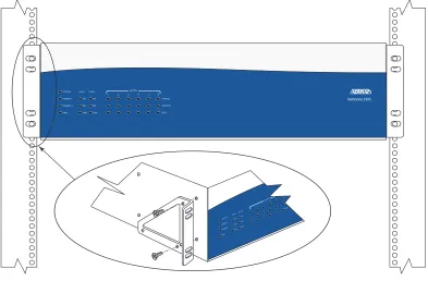
Mounting Options
The NetVanta 5305 may be installed in a 19” or 23” rack mount configuration. The following sections provide step-by-step instructions for rack mounting.
Figure 7. Rack Mounting the NetVanta 5305
Rack Mounting NetVanta 5305
The NetVanta 5305 can be rack mounted in a 19" equipment rack using the mounting kit included with the shipment. Rack mount adapter kits (P/N 12007271L1) can be purchased separately for installation in a standard 23” rack . Follow these steps to mount the NetVanta 5305 into the equipment rack:
Instructions for Rack Mounting NetVanta
Step Action
1. Attach the rack mount ears to the NetVanta 5305 chassis.
2. Position the NetVanta 5305 in a stationary equipment rack. To allow proper grounding, scrape the paint from the rack around the mounting holes where the NetVanta 5305 will be positioned. 3. Have someone else hold the unit in position as you install two mounting bolts through the unit’s
brackets and into the equipment rack.
Installing Modules
The following table lists the installation steps for inserting modules into the NetVanta 5305 chassis.
Grounding Instructions
The following paragraphs provide grounding instructions for the Underwriters’ Laboratory
UL 60950 Standard for Safety of Information Technology Equipment Including Electrical Business Equipment, with revisions dated March 15, 2002.
AC Power
Be careful not to upset the stability of the equipment mounting rack when installing this product.
Improper installation may result in damage to the modules.
Instructions for Installing Modules
Step Action
1. Remove the cover plate from the appropriate option slot of the NetVanta 5305 rear panel using a Phillips screwdriver.
2. Slide the option module into the slot until the module is firmly seated against the front of the chassis.
3. Secure the thumbscrews at both edges of the module. Tighten with a screwdriver. 4. Connect the cables to the associated device(s).
grounding conductor shall be in compliance with the rules for terminating bonding jumpers at Part K or Article 250 of the National Electrical Code, ANSI/NFPA 70. Termination of the supplementary equipment grounding conductor is permitted to be made to building steel, to a metal electrical raceway system, or to any grounded item that is permanently and reliably connected to the electrical service equipment ground.
The supplemental grounding conductor shall be connected to the equipment using a number 8 ring terminal and should be fastened to the grounding lug provided on the back panel of the equipment. The ring terminal should be installed using the appropriate crimping tool (AMP P/N 59250 T-EAD Crimping Tool or
equivalent).
Supplying Power to the Unit
As shipped, NetVanta 5305 is set to factory default conditions. After installing the chassis and any option modules, the system is ready for power-up. To power-up the system, ensure that the unit is properly connected to an appropriate power source (as outlined in the sections which follow).
AC-Powered Systems
The AC-powered NetVanta 5305 comes equipped with a detachable 6-foot power cord with a 3-prong plug for connecting to a grounded power receptacle. To power-up the unit, ensure that the power cord is securely attached to the unit (located on the rear panel) and connect the cord to the appropriate power supply.
Redundant Power Supply (Optional)
A redundant AC power supply may be installed as a backup power supply for the system. The redundant AC power supply can be purchased separately using P/N 1200840L1.
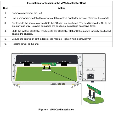
Installing the NetVanta VPN Accelerator Card (4200368L3)
The optional VPN Accelerator Card plugs into a 32-bit PCI slot and is designed to be used in the
NetVanta 5305 to provide encryption/decryption and security acceleration services for the host processor. The card is a 1-U high PC card with gold fingers to interface to a 3.3V keyed PCI connector. It provides the following security services to the host processor: DES, Triple-DES, AES, SHA-1, MD5, and Random Number Generation. The card is powered from the +3.3V rail of the PCI Bus, and the power consumption of the card will not exceed 2 Watts.
• Power to the NetVanta 5305 AC system must be from a grounded 85-250 VAC, 4A/2A, 50/60 Hz source.
Figure 8. VPN Card Installation
Instructions for Installing the VPN Accelerator Card
Step Action
1. Remove power from the unit.
2. Use a screwdriver to take the screws out the system Controller module. Remove the module. 3. Gently slide the accelerator card into the PC card slot as shown. The card is keyed to fit into the
slot only one way. To avoid damaging the card pins, do not use excessive force.
4. Slide the system Controller module into the Controller slot until the module is firmly positioned against the chassis.
5. Secure the screws at both edges of the module. Tighten with a screwdriver. 6. Restore power to the unit.
1
2
3
REMOVE POWER CORD PRIOR TO REMOVAL OF POWER SUPPLY
CAUTION:
Controller Pinouts
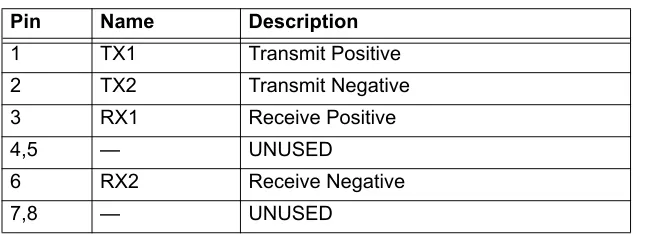
Table A. 10/100BaseT Ethernet Port Pinout
Pin Name Description
1 TX1 Transmit Positive
2 TX2 Transmit Negative
3 RX1 Receive Positive
4,5 — UNUSED
6 RX2 Receive Negative
7,8 — UNUSED
Table B. CONSOLE Port (DCE) Pinout
Pin Name Description
1 DCD Data Carrier Detect (output)
2 RD Receive Data (output)
3 TD Transmit Data (input)
4 DTR Data Terminal Ready (input)
5 SG Signal Ground
6 DSR Data Set Ready (output)
7 RTS Request to Send (input)
8 CTS Clear to Send (output)
9 RI Ring Indicate (output)
Connector Pinouts
Option Module Pinouts
Table C. T1 1/1 Network (RJ-48C) Connection Pinout
Pin Name Description
1 R1 Receive data from the network
2 T1 Receive data from the network
3 — UNUSED
4 R Transmit data toward the network
5 T Transmit data toward the network
6-8 — UNUSED
Table D. T3 Wide Module/T3 Interface (BNC)
Name Description
RX IN Receive data from the network
Table E. HSSI Wide Module Pinout
PIN # (+ side) PIN# (- side) Direction Description
1 26 — HSSI SG - Signal Ground
2 27 I HSSI RT - Receive Timing
3 28 I HSSI CA - DCE Available
4 29 I HSSI RD - Receive Data
5 30 I HSSI LC - Loopback Circuit C
6 31 I HSSI ST - Send Timing
7 32 — HSSI SG - Signal Ground
8 33 O HSSI TA - DTE Available
9 34 O HSSI TT - Terminal Timing
10 35 O HSSI LA - Loopback Circuit A
11 36 O HSSI SD - Send Data
12 37 O HSSI LB - Loopback Circuit B
13 38 — HSSI SG - Signal Ground
14 — — No Connection
15 40 — No Connection
16 41 — No Connection
17 42 — No Connection
18 43 — No Connection
19 44 — HSSI SG - Signal Ground
20 45 — No Connection
21 46 — No Connection
22 47 — No Connection
23 — — No Connection
24 49 I HSSI TM - Test Mode
Numerics
10/100BaseT Ethernet interface 17 pinout 27
A
AC power 24
C
chassis front panel 15 CLI 22
command line interface 22 CONSOLE port 17
pinout 27
contents of shipment 14 controller 18
pinouts 27 customer service 9
F
FCC Regulations 6 features 13 front panel 15
LEDs 16
G
grounding conductor 24 instructions 24H
HSSI DCE Wide option module 20 pinout 29
I
inspecting the system 14 installing
base unit 22 modules 24
VPN accelerator card 26
L
LAN interfaces 17 LEDs 16
M
module 18HSSI 20 installation 24 Octal T1 21 T3 wide 19 mounting options 23
O
Octal T1 wide option module 21 option module 18
HSSI 20 Octal T1 21 pinouts 28 T3 wide 19 overview 15
P
pin assignments 27 pinout
10/100BaseT 27 Console Port 27
HSSI DCE wide option module 29 T1 network connection 28
T3 wide module 28 power supply 25 product registration 9
product support information 9
R
rack mounting 23 rear panel 17 Repair and Return 9
S
shipping contents 14 specifications 13 supplying power 25
T
T1 network connection pinout 28 T1 wide option module 21 T3 wide option module 19
pinout 28
terminal emulation software 22 tools required 22
U
unit installation 22 unpacking the system 14
V
VPN accelerator card 13, 25 installation 26