Adnan M. Alattar and
Sarah Rajala
Center for Communications and Signal Processing Electrical and Computer Engineering Department
North Carolina State University
ccsr-
TR-88/26From A Photograph
Adnan M. Alattar and Sarah A. Rajala Center for Communications and Signal Processing
P.O. Box 7911, North Carolina State University Raleigh, NC 27695-7914
Abstract- The process of locating facial features such as the eyes, nose, mouth and chin in a head and shoulders photograph is very important to any automatic lace recognition system. In this paper, a new algorithm for extracting these major features is developed. The algorithm is based on a model for the human head in a photograph. Since the human head can be viewed as an ellipsoid, the head view in the photograph can be modeled by an ellipse. The algorithm estimates the parameters of the ellipse which best fits the head view in the photograph, and uses these parameters to estimate the locations of the facial features. It then adjusts the vertical coordinates
01
the mouth and nose by using the signature of the pixels in a vertical slit around the nose and mouth. The algorithm has been implemented, and simulation results have verified the accuracy of the estimation of the facial features ' locations.1. Introd uction
While verbal coding describes a picture verbally, geometrical coding uses distance measurements to describe a picture. Goldstein et. al. [1] used verbal coding to develop an interactive face recognition system. Harmon et. al. [2,3,4] used geometrical coding in automatic identification of human face profiles. Each face profile was represented by a vector of seven automatically-extracted fiducial marks. These vectors were then used to compare the profile pictures. Sakai et. al. [5] and Bromley
[6]
developed algo-rithms for automatic location of the facial features in front view images. Sakai [5] used the vertical and the horizontal signatures of the pixels in a slit of predetermined dimensions to determine the location of the facial features. The slit moves around the picture in search of the location of the desired feature. This location must be con-sistent with the locations of other features. Whenever the algorithm detects an incon-sistent location, the process is repeated in an iterative manner. Bromely [6] used a similar algorithm, except that the horizontal and vertical signatures of the global image, rather than of a slit, was used.feature to be extracted or projected is determined manually. Recently, Alattar and Rajala [9] developed a new image coding technique in which facial features are extracted from the input image and then matched to a database. The order of the features in the database, rather than the features themselves, is transmitted to the decoder, where the features are then extracted from an identical database and used to construct a composite image.
In this paper, a one-pass algorithm is developed which quickly and accurately locates the desired facial features. The new extraction algorithm is a model-based algorithm. The art of drawing the human head is used to develop a model for the head in the photograph. In general, this model is good for all types of pictures; how-ever, our discussion and implementation will be restricted to photographs of people with short hair. To extend the work to include people with long hair, one needs to model the face instead of the head. The paper is organized into four sections. Section (2) describes the head model which is used in extracting the necessary features. Sec-tion (3) describes an algorithm for feature extracSec-tion. SecSec-tion
(4)
presents and discusses the simulation results. The last section contains the conclusion and furtherremarks.
2. Model for Head and Shoulder Images
The head of a human being can be thought of as an ellipsoid that sits on the top
then be viewed as rotations ex, ~ , and
e
around the z , y, and z axes, respectively, which pass through the center of the ellipsoid (see Fig.1).
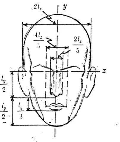
Under this ellipsoid model, the head view in a photograph has the shape of an ellipse. The elongation and orien-tation of this ellipse are related to the head roorien-tation angles ex,f3
and 8. For example, in the front view position, where the angles ( l and ~ are both zero, the length of theminor axis is about two thirds the length of the major axis
[10,11].
However, the ratio changes as the head moves up or down, and therefore is related to the value of angle ex (assuming that the x-y plane is the image plane). The symmetry of the head view in the original image is related to the angle ~, and the tilt of the head, i.e., the orienta-tion of the minor axis of the ellipse, is indicated by the angle 8.Let (c%, cy) be the center of the ellipse that fits the head contour. Also let 1%, Iy
and
e
denote the minor and major semi-axes and the orientation of the ellipse,respec-tively. Using the previously described model of the head and the geometry of the
ellipse, the locations of the eyes, nose, and mouth in terms of (cx,cy ) , 9, lx' and Iy are
given below.
Eyes:
If the length of each eye is
e,
and the centers of the right and left eyes areNose:
fl = (la)
(lb)
(Ic)
If the t'entf'r, length, and base wid th of the nose are denoted by (nr.",nry ) , nh
and nw , respectively, then,
I
=
c - Lsinex 4
1
nc y
=
cy+
Lcos84
nh =
!JL
(2b)
2
u,
(2c)
nw
=
-5
Mouth:
If the center, height and width of the mouth barrel are denoted by (mcz,mcy ), mh and mw , respectively, then,
21
= c - - ysine
x 3
21
mc y = c y
+
- ycosf 3(3a)
(3b)
(3c)
Equations (1)-(3) are used in the facial feature extraction algorithm to estimate the
location of the facial features.
The parameters of the ellipse are estimated by fitting the head contour points
with the ellipse function,
f(x,y;a,b,c,d,e)
=
ax 2+
2bxy+
cy2+
dx+
ey - 1=
0It is easy to show that the center
(c
x 'e
y ) of this ellipse is given byand the orientation
e
is given bycy
=
be - cd
2(
ac - b2)
bd - ae
2(
ac - b2)(5a)
(5b)
e
=
~tan
-1[a
~
c1
The major and minor semi-axes, 1ft and Iy , are givenby
(5c)
A simple way to fit the head contour with the ellipse function is to minimize the fitting error, which is defined by
n
S
=
2:
(~Xi)2+(~Yi)2i=l
(6)
linear equations for the deviation from the initial guess. The process continues until the deviation is so small that no significant improvement in the estimated parameters
can be obtained with further iterations.
3. Facial Features Extraction Algorithm
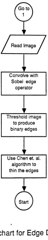
In this section, an algorithm for extracting the facial features, based on the model developed in section (2), is described. The algorithm is summarized in the flowchart of Fig. 3. It consists of five consecutive stages. The first four stages are for the parameters estimation of the ellipse which best fits the head contour. These stages are edge detection, thinning, extraction, and curve fitting. An edge operator is used to enhance the edges. Then, the enhanced image is thresholded to separate significant edges from the background. These edges may be neither thin nor continuous. Although edge continuity is not necessary, it is desired, since it facilitates the extrac-tion of the head contours. Furthermore, thin edges are needed to reduce the ellipse fitting error which the fitting algorithm tries to minimize. Hence, after thresholding the enhanced image, a thinning operator is needed to produce the thinned edges. The outer most head contours are extracted from the thinned image, and the parameters of the ellipse that best fits the contour points are estimated. From the parameters of the ellipse the location of the facial features are estimated.
calculating the vertical signature of the pixels in a slit around the estimated nose or
mouth location. These pixel values are taken from the original binary image before
thinning. The base of the nose or the top and the bottom of the mouth are found
from the signature by marking the start and end of the non-zero values in the slit.
The details of the above process can be summarized in the following algorithm:
Edge Detection:
(1)
Given a head and shoulders image, convolve the image with Sobel's [12}templates (see Fig. J,a) to compute the magnitude of the image gradient.
Threshold the image globally to produce a binary edge image.
Edge Thinning:
(2) Remove all pixels in the image that match one of the Chen et. al
[141
tem-plates (a)-(h), but leave pixels that match template (t) or (J) (see Fig.4
b) .Repeat this step until no further changes occur.
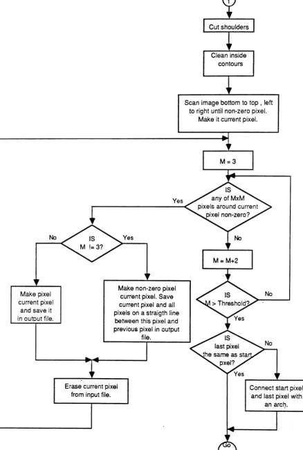
Separating the Head from the Rest of the Body:
(3) Define the boundary which separates the head in the picture from the rest
0/
the body. The boundary is positioned at - 5pixels above the shoulders (first non-zero pixel encountered vertically). Set all pixels in the rows below the
boundary to zero values.
(4)
Scan the image horizontally from left to right and bottom to top, until anon-zero pixel Xo is encountered.
(5) Inspect the pixels in an MXM window (initially 3X3) around the current
non-zero pixel Xi. If another non-zero pixels Xi+1 is found, go to step
(6),
otherwise, increase M and repeat this step as long as M is less than a certain
threshold. Whenever M is greater than the threshold go to step (7).
(6) If M is 3save the location of Xi and make the value of pixel Xi zero. If M is
greater than 9, save the location of Xi and the locations of all pixels on a
straight line between xi and Xi+l' then make the pixel value of pixel Xi zero.
Make pixel Xi+1 the current pixel and go to step (5).
Approximating the Chin Contour:
(7) If the last non-zero pixel on the contour is not the same as the first, connect
them with an arc or two line segments.
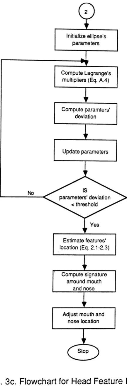
Estimating the Parameters of the Ellipse:
(8) Initialize the parameters a, b, c, d, and e.
(9) Use the contour points to compute Pi in Eq. [a.B], and solve Eq. (A .
.j)
forda, db, S:«, ad, and S:e , (see the Appendix).
(10) Update the parameters a, b , c , d and e using the deltas from step (9). If the magnitude of the deltas is not small enouqh, go to step (9); otherwise go to
Estimating the locations of the Facial Features:
(11) Use the parameters from step (10) to estimate the locations of the facial
features as given byEq.
(1)-(9).
Adjusting the locations of the Facial Features:
(12) Compute the vertical signature in a (mw XI ) slit centered at (c c
+
%1 ).y %' Y Y ,
then choose the position of the last non-zero value in the slit as the base of
the mouth.
(13) Search the signature for the valley of zero values that is closest to the center
of the slit. Choose the starting point of this value as the base of the nose and
the end point as the top of the mouth.
(14) Use the top and base of the mouth to compute the vertical coordinate of the
center of the mouth. Use the base of the nose and the center of the ellipse to
compute the vertical coordinate of the center of the nose.
4. Implementation and Simulation Results
The Chen et. al. algorithm is an iterative parallel algorithm that has proven to be fas-ter than other thinning algorithms due to its property of true parallelism. The tem-plates of this algorithm are shown in Fig. 4b.
When this algorithm was applied to the image of Fig. 5, the images of Fig. 6 were obtained. Fig. 6a is the edge-enhanced image produced by the Sobel operator. The edges in this image were enhanced more than those obtained by other operators. For instance, they are stronger and thinner than those produced by Roberts and Davis operators
[13].
Also, the Sobel operator outperformed Laplacian operator, which produced a lot of undesired noise and inaccurate edges[13].
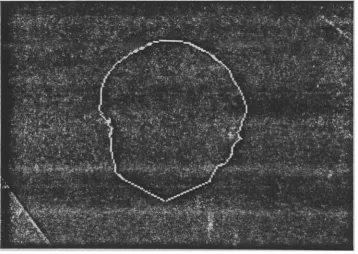
When the average Laplacian operator suggested by Sakai et. al. [5] was used, thick and inaccurate edges were obtained. This type of edge is undesirable because of the later thinning process. The intensity values of the pixels in the enhanced-edge image were rescaled to gray levels (0-255). To produce a binary edge image, each intensity value was thresholded at a global threshold of 35, which was determined from the histogram of the enhanced image. The thresholded image is shown in Fig. 6b. Finally four iterations of the Chen et. al. thinning algorithm produced the thinned image of Fig. 6c.the ellipse of Fig. 6e. The estimated ellipse was superimposed over the head contour for comparison. It was a good fit; the major inaccuracy of the estimation resulted from the fact that the chin part of the contour was missing (Fig. 6d), and it had to be approximated by two straight line segments. The curve-fitting algorithm was fast, and it took only four iterations to obtain an accurate estimation of the ellipse param-eters.
Next, the ellipse parameters were used to estimate the locations of the major features of the face, and the locations indicated by crosses on the image of Fig. 7were obtained. Notice the shift in the mouth and lower part of the nose. This shift has two reasons. The first is the approximation of the lower part of the head by two straight lines. If a curve segment had been used for this approximation, a better approxima-tion of the vertical coordinates of the mouth and the nose would have been obtained. The second reason is that the length of the lower half of the face relative to the upper half varies significantly from one person to another. Hence, the vertical coordinates of the mouth and nose were adjusted using the vertical signature of the pixels in a slit centered at the estimated center of the nose, of length equal to the length of the semi-major axis of the ellipse, and of width equal to the width of the mouth. The adjusted locations are shown in Fig. 8. Obviously, the exact locations of the facial features were found without matching. Notice that it is not necessary to adjust the location of the eyes. The reason is that the length and locations of the eyes with
This algorithm has also been tested on images taken from a sequence of pictures of a speaker. The motion in this sequence was not restricted to planar motion, but consisted of natural and normal motion. The speaker naturally rotates his head to both sides and nodes up and down as he speaks. Ten pictures of different rotation angles were used in the testing process. The rotation angles of those images varied from 0.27° to 7.36°. The picture in Fig. 5 represents the maximum rotation of 7.36°. In all cases, the algorithm produced accurate estimations of the three major facial features.
5. Conclusion
6. Appendix
The following is the solution for the optimization of the parameters of the ellipse that best-fits the head contour.
Let a, b , c , d, e denote the true parameters of the ellipse of best fit, and let a "
i.
c,
d', e' denote an approximate values of these parameters. If(Xi'Yi)denotes a point that lies on the contour of the head, and (Xi' Yi ) denotes the nearest point onthe ellipse, then
(A.I)
e=e'-Ae. Assuming AXi' ~Yi' ~a, ~b, Llc, Lld, and Lle are very small, Eq. (A.I) can be expanded around the point (xi'Yi,a',b',c',d',e') by a Taylor series expansion.
When the higher order terms are ignored, the expansion is given by
al·
-'Abab
ali
ali
ali
f(
Xi'Yi'a,,
b',e,, d"), e - - A x · - -~y. - - A al l ~
ax
ay
vaet
al..
et,
_ iAe _ .~d - - A e
=
0ae
ad
ae
(A.2)
for all
(i=1,2, ...
,n),
where represents the value ofl i
A xax
at(Xi'Yi'a',b',e',d',e ').
Lagrange multiplier method can be used to solve this problem. If we denote hi by the left hand side of Eq. (A.2), the problem is reduced to minimizing the following aug-mented function
1 n
9
=
-8 -2:
Pihi2 i=1
(A.3)
where Pi is the Lagrange multiplier and S is the performance measure. Differentiating this equation with respect to
D.xi' D.Yi, D.a,
Sb ,D.e,
~d, and S:«, respectively, andsetting the result equal to 0, produces the following equations
n
ali
2:
P i - = 0 i=1aa
n ali
2:
P i - = 0i=1 ab
n
ali
2:
P i -=
0i=1
ae
n
ali
2:
Pi---;:;I
=
0 i=1 un
ali
2:
P i -=
0i=1
ae
(A.4a)
(A.4b)
(A.4c)
(A.4d)
(A.4e)
ali~X·
+
p . -=
0I I
ax
ali
~y.
+
p . - = 0t I
ay
for (i=1,2, ...,n)
for
(i=1,2, ...
,n)
(A.5a)
Substituting Eq. (A.5) back into Eq. (A.2) and solving for Pi yields,
where
ali
l u
=• ab
et,
lei
=
ac
I
i =f (
Xi ,Yi ,a ',b',c ',d ',e ')(A.6)
Substituting Eq. (A.6) into Eq. (A.4) produces a set of linear equations which can be easily solved for ~a, ~b, ~c, ~d, and ~e.
Using these equations, an iterative method may be used to solve for the parame-ters of the ellipse. The algorithm starts by calculating the deltas using Eq. (A.6) and
(A.4),
and an initial guess of the parameters of the ellipse. Then, the guess is updated5. References
1. A.J. Goldstein, L.n. Harmon, and A.B. Lesk, "Identification of Human Faces,"
Proceedings of the IEEE, vol. 59, No.5, May 1971, pp. 748-760.
2. L.D. Harmon and W.F. Hunt, "Automatic Recognition of IIuman Face Profiles,"
Computer Graphics and Image Processing, 6, 1977, pp. 135-136.
3. L.D. Harmon, S.C. Kuo, P.F. Farnig, and U. Raudkivi, "Identification of Human Face Profiles by Computer," Pattern Recognition, vol. 10, 1978, pp. 301-312.
4. L.D. Harmon, M.K. Khan, R. Lasch, and P.F. Ramig, "Machine Identification of I-Iuman Faces," Pattern Recognition, vol. 13, No.2, 1981, pp. 97-110.
5. T. Sakai, M. Nagao and Takeo Kanade, "Computer Analysis and Classification of Photographs of Human Faces," Proceedings of the First USA-Japan Computer
Conference, 1972, pp. 55-62.
6. L.K. Bromley, "Computer-aided Processing Techniques for Usage In Real-time Image Evaluation," Master's Thesis, University of Houston, 1977.
7. M.L. Gillenson and B. Chandrasekaran, "A Heuristic Strategy for Developing Human Facial Images on a CRT," Pattern Recognition, vol. 7,1975, pp. 187-196.
8. T.P. Wiederhold, "Facial Image Generation By Computer," Master's Thesis,
University of Houston, 1976.
9. A.M. Alattar and S.A. Rajala, "Primitive-Based Teleconference Image Coding Technique," ICASSP1989, Accepted for publication.
10. B. Hogarth, Drawing the Human Head, 1st ed., Watson-Guptill, New York 1965.
11. S. Simmons III andM.S. Winer, The Creative Process, Prentice-Hall, New Jersey 1977.
13. E.L. Hall, Computer Image Processing and Recognition, Academic Press, New York, 1979.
a. Normal Position
b. Rotation Around Z-axis
c. Rotation Around Y-axis
x
d. Rotation Around X-axis
z
operator
Threshold image to produce binary edges
Use Chen at.at.
algorithm to thin the edges
No
Make pixel current pixel
and save it in output file.
Scan image bottom to top, left to right until non-zero pixel.
Make it current pixel.
Yes
Yes
Make non-zero pixel current pixel. Save current pixel and all pixels on a straigth line
between this pixel and previous pixel in output
file.
Erase current pixel from input file.
Connect start pixel and last pixel with
an arch,
Compute Lagrange's multipliers (Eq, A.4)
Compute paramters' deviation
Update parameters
Estimate features' location (Eq. 2.1-2.3)
Compute signature arround mouth
and nose
Adjust mouth and nose location
~ 1 x
<a>
I 0 0
1 1 0
I 1 :It (e)
0 I x
(b)
o 0
oII
x
I
1I l(0
0 0 0
(e)
x 1 x
0 1 1
0 0 :It
I 1 0
(d)
l 1 x
1 1 0
I 0 0 (h)
o
I
(i)
&Is&on..Tt.'....
(I'SwedafttQI't:It
I 0 II I
'x 1 \ I
I 1 I X 0 I
(j)
Fig. 4. Chen
et.
ale Templates
Fig. 6b. The Result of Thresholding the Image in Figure (6a)
• ,- '.~r:" :~:',' ..',_~.' ..~'., .' . ~ "
-' ,