BAHROM SANUGI MOHD ISMAIL ABD AZIZ
Department of Mathematics, Faculty of Science, Universiti Teknologi Malaysia, 81310 Johor Bahru, Malaysia
Abstract. A complete graph is a fully-connected graph where every node is adjacent to all other nodes in the graph. Very often, many applications in science and engineering are reducible to this type of graph. Hence, a simplified form of a complete graph contributes in providing the solutions to these problems. In this paper, we present a technique for transforming a complete graph into a single-row routing problem. Single-row routing is a classical technique in the VLSI design that is known to be NP-complete. We solved this problem earlier using a method called ESSR, and, the same technique is applied to the present work to transform a complete graph into its single-row routing representation. A parallel computing model is proposed which contributes in making the problem modular and scalable. We also discuss the application of this work on the channel assignment problem in the wireless cellular telephone networks.
Keywords: complete graph, single-row routing, simulated annealing and channel assignments
1. Introduction
In many cases, problems in engineering and other technical problems can be represented as problems in graph theory. A problem of this nature is said to be reducible to the form of vertices and links of a graph, and the solution to the problem can be obtained by solving the graph problem. Furthermore, several solutions to the problems in graph theory have found their roots in some well-known prototype problems, such as the traveling salesman problem, the shortest path problem and the minimum spanning tree problem. Solutions to these problems are provided in the form of dynamic programming techniques, mathematical programming and heuristics. Most of these prototype problems have been proven to be NP-complete and, therefore, no absolute solutions to the problems are established. However, their reduction to the form of graphs have, in some ways, simplified their complexity and pave way for further improvement to their solutions.
are the pins and vias, and the routes consist of non-intersecting horizontal and vertical tracks callednets. The main goal in single-row routing is to find a realization that reduces the congestion in the network.
In this paper, we propose a model for transforming a complete graph as nets in a single-row axis. The motivation for this proposal comes from the fact that some problems in engineering are reducible to the form of a complete graph. A complete graph shows the working relationship between all pairs of nodes in the graph. The relationship, in this case, may represent parameters such as the precedence in a directed flow, the communication cost for transferring data and the matching between the nodes.
This idea may also apply to the subgraphs of the graph in the form of one or more cliques. A clique is a complete subgraph of a graph. Our suggestion in this case is to solve the original problem using the divide-and-conquer approach. The problem may be broken into several components where each component is represented as a clique in the graph. This suggests the formation of a parallel computing model with the cliques forming separate and independent modules. A clique may form its own computing base in a distributed computing system. A group of cliques may form a cluster in a parallel computing system.
In this work, we study the mapping properties of a complete graph into its single-axis representation, in the form of the single-row routing problem. We devise a strategy for map-ping this graph, and then apply the method for solving a graph-reducible problem, namely, the channel assignment problem in the wireless cellular telephone networks. Channel as-signment problem is a NP-hard problem which has its root in the graph coloring problem. The application of the complete graph transformation in the channel assignment problem suggests our method is applicable to the real world applications.
Our paper is organized into eight sections. Section 1 is the introduction. Section 2 de-scribes the problem in the paper, while Section 3 presents the elementary symbols and terminologies used in the paper. In Section 4, we describe the single-row routing problem, while its solution using the simulated annealing method is discussed in Section 5. We also discuss our earlier model called theEnhanced Simulated annealing for Single-row Rout-ing(ESSR) technique in this Section. In Section 6, we outline the details of the mapping strategy for converting the complete graph into its single-row axis representation. For the applications, we propose two parallel computing model for this problem in Section 7 in-volving a single-row multiprocessor network and a cellular network model for the channel assignment problem. We conclude the paper with the summary and conclusion in Section 8.
2. Problem formulation
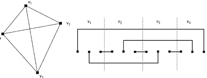
The problem can be stated as follows: given a complete graphCm, how can the edges in this graph be drawn so that they don’t cross each other? The problem here translates into finding a planar graph. Our approach for solving this problem is to transform the complete graph into a single-row routing problem [9], as the single-row representation is a form of planar graph. It is easy to verify that a complete graph,Cm, withmvertices hasm(m−1) links (or edges). This is because each vertex in the graph has a degree of (m−1).
Figure 1. A complete graphC4(left) and its single-row representation (right)..
equals its degree, which is three in this example. The communication links between the nodes are still preserved in this transformation as each zone has exactly one link with all other zones in the network. Therefore, communication between the nodes in the original graph is maintained in this new representation.
The problem begins with the mapping of the links in this graph as terminals in a single-row axis. Single-single-row routing problem is an important component in finding an optimum routing in VLSI design [6, 9]. The single-row representation,Sm, of the graph,Cm, consists ofmzones andm(m−1) terminals, all aligned in a single-row axis. The terminals are to be formed in equally-spaced intervals along the single-row axis. In VLSI, each terminal represents a pin or via. In the single-row routing problem, nets joining pairs of terminals are to be formed to allow communication between the terminals. A net is made up of non-intersecting horizontal and vertical lines that is drawn in the order from left to right.
In order to produce a practical area-compact design, the nets have to be drawn according to the routes that will minimize the wiring requirements of the network. The main objective in the single-row routing problem is to determine the most optimum routing between pairs of the terminals so as to reduce the congestion in the whole network. It is also important that the routing is made in such a way that the interstreet crossings (doglegs) between the upper and lower sections of the single-row axis be minimized. This is necessary as the terminals in the single-row axis are very close to each other, and a high number of interstreet crossings will generate an intolerable level of heat that may cause problems to the network. In optimization, the problem of minimizing the congestion in the network reduces to a search for the right orderings of the nets, based on a suitable energy function.
3. Notations and symbols
Symbols are used based on two categories, namely, a graph and its single-row representation. A graphGconsists of vertices,vj, for j =1,2, . . . ,m, and a set of edges, or links, joining these vertices. To avoid confusion, the nodes in the single-row axis are referred to as
G A graph
Cm A complete graph withmvertices
Sm Single-row representation ofCm
Q Congestion of the nets inSm
D Number of interstreet crossings (doglegs) inSm
E Total energy inSm
L Partial order of nets arranged from top to bottom inSm
vj Vertex j in the graph
dj Degree of vertex j in the graph
m Number of vertices in the graph
ti Terminali
bk Left terminal of netk
ek Right terminal of netk
nk Netk, given asnk =(bk,ek)
ny,i,m Theith net in levelyinSm
by,i,m Beginning (left) terminal of theith net in levelyinSm
ey,i,m End (right) terminal of theith net in levelyinSm
wy,m Width of every net in levelyinSm
ry,m Number of nets in levelyinSm
zj zone jinSm
4. Single-row routing problem
Single-row routing is a combinatorial optimization problem that has been proven to be NP-complete [6, 9]. Traditionally, single-row routing is one of the techniques employed for designing the routes between the electronic components of a printed-circuit board. Each path joining the terminals is called anet. In the single-row routing problem, we are given a set of 2mevenly-spaced terminals (pins or vias),ti, fori=1,2, . . . ,2m, arranged horizontally from left to right in a single horizontal row called the single-row axis.The problem is to constructm nets from the list L= {nk}, for k=1,2, . . . ,m, formed from horizontal intervals, (bk,ek), in the node axis, wherebk andek are the beginning and end terminals of the intervals, respectively. Each horizontal interval is formed from a pair of two (or more) terminals through non-intersecting vertical and horizontal lines. The nets are to be drawn from left to right, while the reverse direction is not allowed.
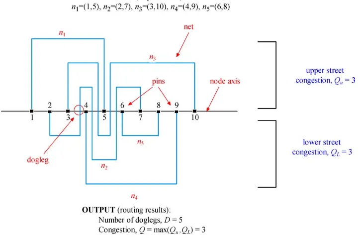
Figure 2 shows a realization in a single-row routing. Physically, each net in the single row represents a conductor path for its terminals to communicate. The area above the single-row axis is called theupper street, while that below is thelower street. The number of horizontal tracks in the upper and lower streets are called theupper street congestion,Cu, andlower
street congestion,Cl, respectively. The overall street congestionQof a realization is defined as the maximum of its upper and lower street congestions, that is,Q=max(Cu,Cl).
Figure 2. Terminologies in the single-row routing problem.
overlapping intervals of a graph. In [2], Du and Liu proposed a heuristic for finding an optimum routing based on a method that sorts the nets according to their classes, internal cut numbers and residual cut numbers.
5. Simulated annealing technique
In this section, we describe our previous method in [8] for solving the single-row rout-ing problem usrout-ing simulated annealrout-ing. Simulated annealrout-ing [3] is a heuristic method for solving combinatorial optimization problems using the atomic properties of particles under-going thermal activities. As demonstrated by Rutenbar [7], it is possible to apply simulated annealing in VLSI design. In his work, simulated annealing has been applied to design an optimum layout for the chip layout and floor-planning.
Simulated annealing involves a massive iterative improvement process of local search for the global minimum of a given energy function. This method is based on the simple and natural technique of trial and error. Initially, the process in simulated annealing requires the definition of a solution space, a cost function and a set of moves that can be used to modify the solution. Through the iterative improvement method, one starts with an initial solution,
x0, and compares this solution with its neighbors. A solution,x, is said to be aneighbor
of a solution,x, ifxcan be obtained fromxvia one of the moves. The neighbors ofx0are examined until a neighborhood solution,x, with a lower cost is discovered. In this case,x
becomes the new solution and the process is continued to examine the neighbors of the new solution. The algorithm terminates when it arrives at a solution which has no neighboring solution with a lower cost.
In our problem, a pertubation is performed to examine the neighbors by moving a net at random to a new position. The resulting change in energyE is then evaluated. If the energy is reduced, that isE<0, the new configuration is accepted as the starting point for the next move. However, if the energy is increased, E>0, the move generates the probability of acceptance, given by Pr[acceptance]=e−E/T. The move is accepted if this probability is greater than a threshold probability of acceptance,ε, and rejected otherwise. The value ofεis proportional to the rate of acceptance or rejection. With a higher value, the number of moves accepted forE>0 are reduced and the same rule applies vice versa.
Our objective in this problem is to obtain a realization that minimizes both the street congestion, Q,and the number of doglegs, D. However, this objective is very difficult to achieve as the two components are separate but dependent entities. While having one component minimized, the other tends to show some resistance to its minimization. In [8], we proposed the Enhanced Simulated annealing for Single-row Routing (ESSR) method based on simulated annealing that produces a routing that minimizes both the congestion and the number of interstreet crossings. Figure 3 illustrates how ESSR is implemented to solve the single-row routing problem.
To express the above requirement, the energy in a given net ordering is expressed as the total length of all the tracks, according to the energy function,E, derived from our earlier work, as follows:
E=
M
k=1 Mk
j=1
|hk,j|. (1)
In the above equation,hk,j is the energy of segment jin netk, while Mis the number of nets in the problem andMkis the number of segments in netk.
6. Complete graph partitioning strategy
Figure 3. ESSR method for the single-row routing problem.
6.1. Formation of zones and terminals from a complete graph
InCm, every link between a pair of vertices in the graph is mapped as a terminal inSm.
Therefore, aCmgraph havingmvertices andm(m−1) links is mapped intomzones with a total ofm(m−1) terminals inSm. A vertex with degree jin the graph occupies a zone in
Smwithdj terminals.
Our method for creating the zones and their terminals inSmfrom a complete graph,Cm, is outlined inAlgorithm 1, as follows:
/*Algorithm 1: Formation of zones and terminals inSmfromCm*/ Given a complete graphCm;
Draw the zones,zj,inSm,which corresponds tovjinCm,for j =1,2, . . . ,m; for j =1tom
Determine the degree,dj,of every vertex,vj,inCm; Set i =1;
for k=1todj
Set the terminal number,ti =i; Update i ←i+1;
6.2. Construction of nets from a complete graph
In the previous section, we described a plan to form the zones and nets inSmfromCmusing Algorithm 1. We illustrate the idea on the problem of forming a single-row representation of C5, a complete graph withm = 5 vertices. In this problem, each vertex in the graph has a degree of 4. There are m = 5 zones, zi, fori = 1,2, . . . ,5 and the number of terminals on the single-row axis ism(m−1)=20. Hence, the number of nets formed is
rm = m(m2−1) =10. Figure 4 shows the zones and terminals inS5 formed fromC5 when Algorithm 1is applied.
We now present a technique for forming the nets in the network that contributes in mini-mizing the total energy inSm. The technique calls for the formation of the nets by grouping them first into several levels based on their width. The widthof netk, denoted aswk, is defined as the difference between its beginning and end terminals, given aswk=ek−bk.
by,i,m=(m−y)+(m−1) (i−1), (2a)
ey,i,m=by,i+wy,m (2b)
fory=1,2, . . . ,m−1, andi =1,2, . . . ,m−1.
From Proposal, we obtain the width of the nets in levelyofSm, given as follows:
wy,m =1+(m+1)(y−1), (3)
and the number of nets in each level as follows:
ry,m=(m−y). (4)
The strategy for grouping the nets into levels based on their width is to minimize the total network energy, given in Equation (1). This goal can be achieved by forming nets starting from the shortest width, continue with the next shortest and so on. Starting with level 1, that is, y =1, the nets are formed from two consecutive terminals from two different zones. This level has the most minimum width possible, given byw1,m=1. This minimum width has the advantage of producing the net energy equals 0, as the net can be drawn directly on the node axis. Theith net is formed from the last terminal inzi and the first terminal in zone (i+1)th, to make sure that the width remains the same. Using Equations (2a) and (2b) from Proposal, we then obtain theith net in this level,n1,i,m=(b1,i,m,e1,i,m), given as
b1,i,m=(m−1)+(m−1)(i−1) ande1,i,m =b1,i+1.
In level 2, the first net is obtained by having the second last terminal inz1as its beginning terminal, and the second terminal of z2 as the ending terminal. This gives the width as
w2,m=1+(m+1)=m+2. In general, theith terminal in this level,n2,i,m =(b2,i,m,e2,i,m), is given byb2,i,m=(m−2)+(m−1)(i−1) ande2,i,m=b2,i+w2,m.
/*Algorithm 2: Construction of nets inSm*/ Given a complete graphCmwithmvertices; Let the number of nets in level 1,r1=r;
The initial width of nets in level 1 is 1, that is,w1,m=1; for y=1tor
if y>1
Update the width of the nets in levely,wy,m←1+(m+1)(y−1); Update the number of nets in levely,ry,m←(m−y);
for i =1tory
Form the ith net in levelyas follows:
Update the left terminal of nety,by,i,m←(m−y)+(m−1) (i−1);
Update the right terminal of nety,ey,i,m←by,i+wy,m; for y=1,2, . . . ,r
for i =1,2, . . . ,ry
Sort(bs,i,m,es,i,m)in ascending order withbs,i,mas the primary key; for k=1to m(m−1)
2
Assignnk=(bk,ek)from the sorted(bs,i,m,es,i,m);
We illustrate the idea of constructing the nets using Proposal through the example in Figure 4. In this figure, a complete graph with 5 vertices,C5, maps asS5. The zones and terminals are obtained by applyingAlgorithm 1. By applying Equations (2a) and (2b) from Proposal 1, we obtain the nets grouped into 4 levels, as shown in Figure 4.Algorithm 2transforms theC5 into S5. Table 1 shows the nets obtained from this construction. We then applyESSRto the nets to obtain the results in the form of an ordering with minimum energy,E =11, as shown in Figure 5. The final realization of the network withQ=3 and
D=1 is shown in Figure 6.
We also apply the method to several other models of complete graphs. Table 2 summarizes the results of these graphs withmvertices,Cm, in their single-row representations. Figure 6 shows the final realization of the routing obtained using ESSR fromC10.
7. Parallel computing model
Single-row routing technique is not restricted to the design of the printed-circuit boards only. We explore other potential benefits and suggest two of them in this section.
Table 1. Formation of nets inS5fromC5
Level,y Width,wy,5 #nets,ry Nets
1 1 4 (4,5), (8,9), (12,13), (16,17)
2 7 3 (3,10), (7,14), (11,18)
3 13 2 (2,15), (6,19)
Figure 5. Nets ordering with minimum energy,E=11, ofC5using AlgorithmESSR.
Figure 6. Final realization ofC5withE=11,Q=3 andD=1.
Figure 7. Realization of an optimum assignment of 45 nets fromC10in Table 2.
7.1. Single-row multiprocessor system
The transformation results in the form of non-crossing nets in the single-row model suggest the nets are independent of each other. In a single-row routing without doglegs, communi-cation between the pairs of terminals in the single row can be established without passing through any intermediate node. A model called a single-row multiprocessor system is pro-posed, as shown in Figure 8. In this diagram, the processors are the shaded rectangles arranged in the single-row axis. The circles in the upper and lower streets of the network are the switches which can route the communicating lines into the north, south, east and west directions. Each communicating line in this network model is called a bus.
Figure 9 shows another single-row multiprocessor model which involves doglegs. This model is derived from the transformation results of the complete graphC5into the single-row model S5, which produces five zones. The routing results are obtained from ESSR with an optimum congestion of three and one dogleg. In this model, each zone formed in the single row axis is represented as a processor while the terminals form the ports in the processors. The processors in this diagram are labeled as pi, fori=1,2, . . . ,5. A dogleg in the network means the net between terminals 3 and 11 crosses the single row axis through
p2. In this case, an extra port is created in this processor to enable the crossing to take place. It follows that doglegs can be represented as extra terminals in the host processors at the crossings.
7.2. Application to the channel assignment problem
The single-row mapping strategy can also be applied to the problem of assigning radio channels in a wireless cellular telephone network. In the wireless cellular telephone net-work [5], the assignment of radio frequencies to the mobile users within the netnet-work can be modeled as the problem of mapping a complete graph into non-intersecting single-row nets. This network consists of a geographical region partitioned into several cells where each cell is allocated with a base station (BS). A base station has a transmit-ter and a receiver for receiving and transmitting messages from/to mobile users within its cell. The base stations in the network are linked with high-speed cables to the mo-bile switching center (MSC), which functions as a controller to allow communication between any two mobile users in the network by assigning a channel each to each of them.
Figure 10. Single-row routing model for the cellular network.
pair of different channels to both the caller and the receiver, to allow immediate circuit switching.
In the channel assignment problem, we model the channels as the edges of a complete graph. The cells in the network are then represented as nodes in the graph. In the single-row axis, each of these cells is a zone and the channels allocated to a cell are terminals in the zone. Communication between two mobile users from two different cells is established through a net linking their two terminals. We model the single-row communication to be handled by the mobile switching center. This is because MSC has a control on all channel assignments in the network, and this important task must be done immediately without delay when requests for calls are received. In addition, MSC must also be able to provide services associated with problems in channel assignments, such as location finding of mobile users, and channel handovers as a mobile user moves from one cell to another.
assignment problem in the wireless cellular telephone networks.
References
1. J. S. Deogun and N. A. Sherwani. A decomposition scheme for single-row routing problems. Technical Report Series #68, Dept of Computer Science, Univ. of Nebraska, 1988.
2. D. H. Du and L. H. Liu. Heuristic algorithms for single row routing.IEEE Trans. Computers, 36(3):312–319, 1987.
3. S. Kirkpatrick, C. D. Gelatt, and M. P. Vecchi, Optimization by simulated annealing.Science, 220(4598):671– 678, 1983.
4. E. S. Kuh, T. Kashiwabara, and T. Fujisawa, On optimum single-row routing.IEEE Trans. Circuits and Systems, 26(6):361–368, 1979.
5. R. Mathar and J. Mattfeldt, Channel assignment in cellular radio networks.IEEE Trans. Vehicular Technology, 42(4), 1993.
6. R. Raghavan and S. Sahni, Single row routing.IEEE Trans. Computers, 32(3):209–220, 1983.
7. R. A. Rutenbar, Simulated annealing algorithms: An overview.IEEE Circuits and Devices Magazine, 19–26, 1989.
8. S. Salleh, B. Sanugi, H. Jamaluddin, S. Olariu, and A. Y. Zomaya. Enhanced simulated annealing technique for the single-row routing problem.Journal of Supercomputing, 21(3):285–302, 2002.