ASSESSMENT OF THE DISCRETE ELEMENT METHOD (DEM) IN
THE PREDICTION OF CONCRETE BEHAVIOR IN 3D COMPRESSION
Jorge D. Riera1, Letícia F. F. Miguel2 and Ignacio Iturrioz2
1
Invited Professor, Civil Eng. Dept., Univ. Federal do Rio Grande do Sul, RS, Brazil.
2
Associate Professor, Mechanical Eng. Dept., Univ. Federal do Rio Grande do Sul, RS, Brazil
ABSTRACT
The authors successfully employed the Discrete Element Method (DEM) in numerical determinations of the response up and beyond failure of reinforced concrete structures subjected to impact and impulsive loadings in which tensile fractures, which are reliably predicted by DEM models, often control the dominant failure modes. However, in impact problems when penetration occurs, the reliability of the approach in predictions of the structural response of the 3D compression zone that develops at the tip of the projectile has not yet been explicitly confirmed. In this context, the performance of the method is herein assessed and compared with available experimental results. By means of numerical simulations, it is verified that DEM models closely predict the strengths measured on concrete cubes subjected to multi axial compression and the global behavior up to failure, for confining (lateral) pressures up to about 20% of the principal compressive stress. For applied stress distributions approaching isotropic compression, however, the present DEM formulation appears to overestimate the failure envelope, topic that is currently under investigation. The influence of concrete fracture properties adopted in the analysis as well as the effect of the mesh imperfections introduced in the model to improve its prediction capabilities are thoroughly examined.
INTRODUCTION
Krajcinovic (1996) classifies the methods proposed to predict the damage process in quasi-fragile materials in two large groups, those based on Continuum Mechanics and the so-called Statistical or Discrete Models approach. In the former, Plasticity Theories are extended to study the damage process, leading to procedures that encounter serious difficulties when dealing with quasi fragile materials. An example of the Continuum Mechanics approach is the model recently proposed by Araoz and Luccioni (2015) for 3D compression in quasi-fragile materials. On the other hand, Statistical or Discrete Models still lack the versatility of the finite element approach, but in compensation problems such as localization, anisotropic damage evolution and associative effects between different parts of the solid under study can be accounted for with relative facility. Lattice models, of which the present DEM formulation is a special case, belong to this group.
Basically, the solid is modeled by means of an array of uniaxial elements, which interconnect nodal masses with three degrees of freedom. The initial stiffness of these elements can be determined from the mechanical properties of the anisotropic solid to be represented by the DEM. The Lattice DEM formulation used in this paper was proposed by Riera (1984) to predict the dynamic response of plates and shells under impact loading, when failure occurs primarily by shear or tension, which is generally the case in concrete structures. The constitutive criterion was based on Hillerborg’s model (1971). DEM applications in studies of non-homogeneous materials subjected to fracture were reported by Miguel et al.
influence of confining pressures, its performance in the prediction of concrete response under 3D compression has not been previously assessed. This paper presents DEM predictions of the response of cubic and prismatic concrete samples subjected to 3D compression tested by Van Geel (1998). Predictions of the peak compressive stresses and of the rupture configurations compatible with experimental results were made, introducing imperfections in the cubic mesh geometry as suggested by Iturrioz et al. (2014). Herein the technique is extended by examining further which is the optimum range of the imperfections amplitudes that should be introduced in the mesh to attain best correlations of the numerical response with standard laboratory tests employed to determine concrete properties.
THE DISCRETE ELEMENT METHOD IN FRACTURE PROBLEMS
The computational model employed in this paper is based on the representation of a solid by means of an arrangement of elements able to carry only axial loads. The equivalence between an orthotropic elastic continuum and the cubic arrangement of uni-axial elements, shown in Figure 1, consisting of a cubic cell with eight nodes at its corners plus a central node was shown by Nayfeh and Hefzy (1978). The discrete elements representation of the orthotropic continuum was adopted by Riera (1984) to solve structural dynamics problems by means of explicit direct numerical integration of the equations of motion, assuming the mass lumped at the nodes. Each node has three degrees of freedom, corresponding to the nodal displacements in the three orthogonal coordinate directions. For a cubic arrangement, the lengths of longitudinal and diagonal elements are L0 and ¥3L0/2, respectively. The
equations that relate the properties of the elements with the elastic constants of an isotropic medium are:
in which E and ν denote Young’s modulus and Poisson’s ratio, respectively, while An and Ad represent the areas of normal and diagonal elements, as shown in Figure 1(a). It is important to point out that for ν = 0.25, the discrete model representation exactly coincides with the isotropic continuum formulation, while for other values of ν small errors appear in the shear terms. Moreover, the model does not admit a value of Poisson’s ratio equal to 0.5, which is not a deficiency of the method, since incompressible materials do not exist. The resulting equations of motion may be written in the well-known form:
in which x& represents the vector of generalized nodal displacements, M the diagonal mass matrix, C the damping matrix, also assumed diagonal, F tr
( )
&
and P t
( )
&the vectors of internal forces acting on the nodal masses and the vector of external forces. Obviously, if M and C are diagonal, Eq. (2) is not coupled. Then the explicit central finite differences scheme may be used to integrate it in the time domain. Since the nodal coordinates are updated at every time step, large displacements can be easily accounted for.
9 4 8 ν δ ν = − ,
(
)
(
)
2 9 8 2 9 12
n
EA EL δ
δ + = + , 2 3 3 d n
EA = A E (1)
( )
( )
0r
x+ x+F t −P t =
M C
& & & &
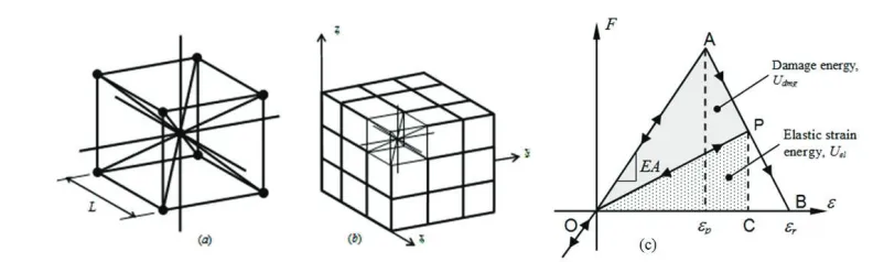
Figure 1: DEM discretization strategy: (a) Basic cubic module, (b) Generation of a prismatic body, (c) Bilinear constitutive law adopted for DEM uni-axial elements.
Non-Linear Constitutive Model for Material Damage
The softening law for quasi-fragile materials proposed by Hilleborg (1971) was adopted to model the behavior of quasi-fragile materials by means of the triangular elemental constitutive relationship (ECR) for the DEM bars presented in Figure 1 (c), which allows accounting for the irreversible effects of crack nucleation and propagation. The area under the force vs. strain curve (the area of the triangle OAB) is related to the energy density necessary to fracture the area of influence of the element. Thus, for a given point P on the force vs. strain curve, the area of the triangle OPC quantifies the energy density dissipated by damage. Once the damage energy density equals the fracture energy, the element fails and loses its load carrying capacity. On the other hand, under compression the material is assumed linearly elastic. Thus, failure in compression is induced by indirect tension. Constitutive parameters and symbols shown in Figure 1(c) are defined below: the element axial force F depends on the axial strain İ. An equivalent fracture area Ai* of each element is defined in order to satisfy the condition that the energy dissipated by fracture of the continuum and by its discrete representation are equivalent. With this purpose, fracture of a cubic sample of dimensions L×L×L is considered. The energy dissipated by fracture of a continuum cube due to a crack parallel to one of its faces is ī = Gfȁ = Gf L2, in which ȁ is the actual fractured area, i.e.,
L2. On the other hand, the energy dissipated when a DEM module of dimensions L×L×L fractures in two parts consists of the contributions of five longitudinal elements (four coincident with the module edges and an internal element) and four diagonal elements. The energy dissipated by a cubic DEM module and its distribution in the various elements were examined by by Iturrioz et al. (2014), and will not be reproduced here on account of space limitations.
Random Distribution of Material Parameters in the DEM Environment
Miguel et al. (2010) modeled the random properties of the material, defining the toughness Gf as a random field with a Type III (Weibull) extreme value distribution, given by Eq. (3):
( )
f 1 exp(
f)
F G = − ª«− G β γº»
¬ ¼ (3)
in which ȕ and Ȗ are the scale and shape parameters, respectively. The mean value ȝ and the standard deviation s of Gf are given by:
(
1 1)
µ=⪬à + γ º¼ ; s βª
(
1 2γ)
2(
1 1γ)
º1 2elements able to carry only axial loads, interconnected at nodal masses with three degrees of freedom. The initial elastic stiffness of the interconnecting elements is determined, for the cubic and other arrangements, in terms of the local elastic properties of an orthotropic solid, which may be non-homogeneous, by means of available sets of equations. The introduction of small perturbations of the cubic arrangement, generated by small initial displacements of nodal points, should also result in small changes in the stiffness of the elements, which will tend to zero as the initial nodal displacements vanish. Hence, it is herein assumed that the stiffness coefficients of the DEM model remain unaltered by small perturbations of the mesh. Moreover, the linear response of the model should remain unaltered within the range of interest, whose upper limit will be established later. Basically, it is assumed that the nodes in the perturbed model are displaced from their position in a perfect cubic arrangement, defined by nodal coordinates (xn , yn , zn), as indicated in Eq. (5):
(xn+rx L, yn+ry L, zn+rz L) (5)
in which rx, ry and rz are random numbers with a normal distribution with zero mean and coefficient of variation CVp. L denotes the length of the longitudinal elements in the cubic cell. The CVpvalue that best fits the experimental evidence was determined by numerical experimentation.
SIMULATION OF VAN GEEL’S EXPERIMENTAL RESULTS
Figure 2: Experimental results for normal concrete of Van Geel (1998).
0 0.1 0.2 0.3 0.4 0.5 0.6 0.7 0.8
0 20 40 60 80 100 120 140 160 180
Displacement (mm)
N
o
rm
al
S
tr
es
s
(M
P
a)
sx = sy = 0 MPa sx = sy = 0 MPa (slow) sx = sy = 1 MPa sx = sy = 3 MPa sx = sy = 10 MPa
Figure 3: Numerical results obtained by DEM.
Figure 3 shows numerical simulations of the response of 0.10m cubes subjected to (a) unconfined concrete compression (black line), (b) confined compression with ıx = ıy = 1MPa (blue line), (c) idem, ıx
= ıy = 3MPa (red line) and (d) ıx = ıy = 10MPa (green line). The black thin line corresponds to an applied vertical displacement rate equal to 1/5 to the rate of the continuous thick lines, to illustrate the influence of the velocity of loading. The increase of the unconfined compressive strength of normal concrete, in presence of confining stresses ıx = ıy predicted by DEM simulations and by Van Geel’s experimental results, for ıx = ıy < 10MPa, are given by the linear approximation equations (6) and (7), respectively:
(ız)u = fco[ 1 + 12.7 (ıx/ fco)] (6)
(ız)u = fco[ 1 + 7.6 (ıx/ fco)] (7)
formulation does not capture the observed nonlinearity of the volumetric response under approximately isotropic compression.
REFERENCES
Araoz, G. and Luccioni, B. (2015): "Modeling concrete like materials under severe dynamic pressures", International Journal of Impact Engineering, Elsevier, 76, 139-154.
Gross D. and Seelig T. (2006). “Fracture Mecanics with and Introduction to Micromechanics”, Mechanical Engineering Series. Ed. Ling F. F., Springer. p319. doi 10.1007/b22134.
Hillerborg, A. (1971): “A model for fracture analysis”, Cod. LUTVDG/TVBM 300-51-8, 1971.
Iturrioz, I., Riera, J.D. and Miguel, L.F.F. (2014): “Introduction of imperfections in the cubic
mesh of the truss-like Discrete Element Method”, Fatigue and Fracture of Engineering
materials and Structures, Sage Publ. Co., Vol 1, 2014
Krajcinovic D., (1996) “Damage Mechanics”. Elsevier, Amsterdam.
Miguel, L. F. F., Iturrioz, I., and Riera, J. D., (2010). “Size effects and mesh independence in Dynamic Fracture Analysis of Brittle Materials.” Computer Modeling in Engineering & Sciences, Vol. 56, No. 1, pp. 1-16.
Nayfeh, A. H. and M. S. Hefzy (1978), “Continuum modeling of three-dimensional truss-like space structures”, AIAA Journal, 16(8), 779-787.
Nemat-Nasser, S. and Horii, H., (1982), Compression-Induced Nonplanar Crack Extension with Application to Splitting, Exfoliation and Rock Burst, J. Geophys. Res., Vol. 87, pp. 6805-6821. Puglia, B.V., Iturrioz, I, Riera, J.D., Kosteski, L. (2010), “Random field generation of the material
properties in the truss-like discrete element method”, Mec. Comp., Cilamce-Mecom 2010, Vol. XXIX, pp. 6793-6807.
Riera, J.D. (1984): “Local effects in impact problems on concrete structures”. Proceedings, Conference on Structural Analysis and Design of Nuclear Power Plants. Oct. 1984, Porto Alegre, RS, Brasil, Vol. 3, CDU 264.04:621.311.2:621.039.
Riera, J.D., Iturrioz, I. (1998): “Discrete elements model for evaluating impact and impulsive response of reinforced concrete plates and shells subjected to impulsive loading”. Nuclear Engineering and Design, Vol. 179, pp. 135-144.
Riera, J.D., Miguel, L.F.F., Iturrioz, I., (2011): “Strength of Brittle Materials under High Strain Rates in DEM Simulations”, Computer Modeling in Engineering & Sciences, Vol. 82, pp. 113-136. Van Geel, E. (1998): “Concrete behavior in multi-axial compression”, Doctoral Dissertation, Technische