Study of the effect of temperature on the positioning accuracy of
the pneumatic muscles
Pawel Andrzej Laski 1
, Slawomir Blasiak 1, Jakub Emanuel Takosoglu 1, Dawid Sebastian Pietrala 1
, Gabriel Filip Bracha1
,
Jaroslaw Zwierzchowski 1
, Lukasz Nowakowski1 Krzysztof Borkowski 1, Malgorzata Blasiak 1
1
Kielce University of Technology, Faculty of Mechatronics and Mechanical Engineering, Aleja Tysiaclecia Panstwa Polskiego 7, 25-314 Kielce, Poland
Abstract. The article concerns experimental studies of the effect of temperature on the positioning accuracy of pneumatic muscles. It presents results of experimental studies in the form of thermal images from thermal imaging camera. Pneumatic artificial muscles have unique operational characteristics and because of that they are used in industrial production processes, where classic drives do not work. During operation of muscles with large frequencies above 60 Hz, one can observe a significant increase in temperatures on the bladder surface. The article concerns a study aimed at the determination of the maximum temperature which can be achieved and whether it affects the accuracy of their positioning.
1 Introduction
Pneumatic drive is widely used in all branches of industry and is the most environmentally friendly energy carrier [1–11]. It uses a vacuum or compressed air, which after the operation is returned directly to the atmosphere without the need for using filtering devices, as it does not contain any impurities [12–20]. Artificial muscle drives have been known since 1929. Dimitri Sensaud de Lavaud was the first to invent the pneumatic artificial muscle and then the muscle invented by Garasiev could be powered either by compressed air or other liquids. It was built from a stretchable membrane surrounded by a non-stretchable braid on the outside.
Because of the unique functional characteristics of artificial muscle drives when compared to conventional pneumatic actuators, they are used as drive elements in anthropomorphic robots, bionic and humanoid bioprosthetics, manipulators used for rehabilitation and physiotherapy, and more often in the automation of production processes [21–31]. Pneumatic artificial muscles PAM can be compared with single-acting actuators due to the way they function [32].
Pneumatic artificial muscles which, in comparison with the known and widely used systems, are distinguished primarily by soft start and soft stop. In addition, pneumatic artificial muscles have a high resistance to overload, they are characterized by high dynamics, the lack of indexing working movement (the phenomenon of stick–slip) and, most importantly, very low consumption of compressed air, which places them in the group of energy efficient drives. The pneumatic artificial muscle is a highly energy efficient drive and has ten times the initial force in comparison with the power actuator of the same diameter.
Currently, there are two most commonly used types of pneumatic muscles, in which the tight and elastic bladder is braided with small mesh (net or sleeve) of small geometric dimensions and a certain angle of weave and suitable elastic properties. In the latter case, the braid is vulcanized with an elastic bladder. The braid (fine mesh) is mounted at the ends of the muscle, creating a certain kind of artificial tendon. The value of generated force depends on the pressure of gas, its original length, the degree of shortening and material properties.
2 Experiential stand
muscle is being drained. After switching the valve to the second extreme position, the process is reversed and the drained muscle is being filled while the filled muscle is being drained. The experiential stand was designed to imitate the most common way of using the muscles in driving mechanisms [30,33]. Since the pneumatic artificial muscle has only the ability of shortening, in order to achieve the return movement one uses the opposite muscle acting antagonistically as it does in living organisms. Piezoresistive pressure transmitters with analog output of 0–10 V were used to measure the pressure inside of the pneumatic muscle. The reading of pressure inside of the pneumatic muscle and the value of its shortening is performed using real-time system, built on the basis of the Matlab/Simulink package and measurement cards. Measurement cards (AD and DA) [34–36] are installed on the PC Target from speedgoat [7,8,37–42]. Experimental studies were carried out for the pneumatic muscle from Festo Fluidic Muscle DMSP-10-300. The nominal length of the muscle before shortening amounted to 300 mm and the diameter amounted to 10mm. Figure 3 shows a cross section of the pneumatic muscle from Festo.
Fig. 1. The principle of measurement on the experiential stand.
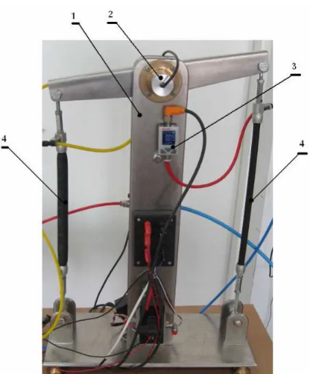
Fig. 2. General view of the experiential stand used to study the effect of temperature on the positioning accuracy of pneumatic muscles: 1 – bearing structure, 2 – position sensor, 3 – pressure sensor, 4 – tested muscles.
2.1 Operation of the pneumatic muscle
The operation of a muscle drive (shortening) is caused by the increase in air pressure within the elastic bladder. The increase in pressure causes the simultaneous increase of the circuit at the expense of reducing the length of a muscle. As a consequence, it increases the shrinkage of a muscle and forms an axial tensile force corresponding to stresses in the braid (mesh). The greatest force of the muscle drive is achieved in the initial phase of the movement, which decreases to zero at the maximum of its shrinkage, but only in the presence of constant pressure.
Through the control of pressure changes, one can control the force generated by the muscle, and the degree of its shortening.
The use of pneumatic muscle drives allows for efficient and economical management of the consumed compressed air in circuits that control the device. The consequence of this is the reduction of emitted carbon dioxide and other pollutants generated during the production of electricity. However, as a result of the operation of muscles with high frequencies, a fraction of the energy is dissipated and transformed into heat. One can observe a visible temperature increase of the working muscles.
phase of the movement, since it can cause permanent damage to its structure.
Fig. 3. Cross section of the DMSP muscle from Festo.
3 Experimental study of the DMSP
muscle drive
The studies of the positioning accuracy of muscles drives involved an alternant shrinkage of muscles working antagonistically. The inducement signal had the form of a sine wave that ensures a gentle way of filling and draining the muscles. The muscles were working alternately at a frequency of 20 Hz (they reached full shortening). They were unilaterally powered by compressed air. The studies were carried out to the point of reaching temperatures in the range of 31 ÷ 51ºC with a step every 5ºC.
Figures 4-8 show thermographic images [43–45] for temperatures in the range of 31 ÷ 51ºC, obtained using the VIGO cam V50 thermal imaging camera.
Fig. 4. An image of the DMSP muscle at the temperature of ~31 ºC obtained using thermal imaging camera.
Fig. 5. An image of the DMSP muscle at the temperature of ~36 ºC obtained using thermal imaging camera.
Fig. 6. An image of the DMSP muscle at the temperature of ~41 ºC obtained using thermal imaging camera.
Fig. 8. An image of the DMSP muscle at the temperature of ~51 ºC obtained using thermal imaging camera.
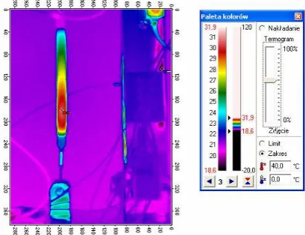
Figure 9 shows an image of the experiential stand obtained using thermal imaging camera [9,46], with visible muscles where the highest temperature is observed at fittings of the muscle.
Fig. 9. View of the experiential stand in a thermographic image.
Dynamic characteristics were presented in figure 10 and figure 11 in order to compare the studies conducted for temperatures reached by muscles and their influence on the positioning accuracy.
Fig. 10. Dynamic characteristics of the DMSP muscle for temperatures in the range of 31ºC, 36ºC, 41ºC, 46ºC, 51ºC
Fig. 11. Zoom in on part of dynamic characteristics of the DMSP muscle for temperatures in the range of 31ºC, 36ºC, 41ºC, 46ºC, 51ºC.
4 Conclusions
Because of their unique characteristics, muscle drives find new applications in medicine and industry. It has been shown that the increase in temperatures of muscles as a result of dynamic operation have little effect on the achieved positioning accuracy of muscle drives (figure 10 and figure 11). The increase in muscle temperature results from friction of the braid (mesh) on the elastic bladder. In addition, the muscle was warming up to a greater extent at the bottom connection. This results directly from the heat exchange processes. The upper part of the muscle was filled with new “cold” volume of air 20 times within one second. This resulted in a greater dissipation of thermal energy. It was also observed that attempts to increase the frequency of switching the muscles to achieve higher surface temperature did not result in its increase. Thermal equilibrium was achieved spontaneously. This knowledge allows for safe use of pneumatic muscles with considerable frequencies of operation without concern of damage resulting from the increase in temperature of the drive.
The experiential stand used to determine the dynamic characteristics of muscle drives is protected by patent PL 223042 B1.
References
1. J.E. Takosoglu, (Acad Sci Czech Republic, Inst Thermomechanics, Dolejskova 5, Prague 8, 182 00, Czech Republic, 2016).
2. J.E. Takosoglu, P.A. Laski, S. Blasiak, (Acad Sci Czech Republic, Inst Thermomechanics, Dolejskova 5, Prague 8, 182 00, Czech Republic, 2014).
3. J.E. Takosoglu, R.F. Dindorf, P.A. Laski, International Journal of Advanced Manufacturing Technology. 40 (3–4) (2009), 349–361.
4. J.E. Takosoglu, P.A. Laski, S. Blasiak, Proceedings of The Institution of Mechanical Engineers Part I-Journal of Systems And Control Engineering. 226 (I10) (2012), 1335–1343.
5. J.E. Takosoglu, R.F. Dindorf, P.A. Laski, International Journal Of Advanced Manufacturing Technology. 40 (3–4) (2009), 349–361.
a
ngu
la
r di
s
p
la
c
e
m
e
nt
(
d
6. J.E. Takosoglu, P.A. Laski, S. Blasiak, G. Bracha, D. Pietrala, Measurement & Control. 49 (2) (2016), 62–71.
7. R. Trochimczuk, in: Gosiewski, Z and Kulesza, Z (Ed.), Mechatronic Systems And Materials Iv, Trans Tech Publications Ltd, Laublsrutistr 24, Ch-8717 Stafa-Zurich, Switzerland, 2013: pp. 3–8. 8. R. Trochimczuk, M. Gawrysiak, in: Gosiewski, Z
and Kulesza, Z (Ed.), Mechatronic Systems And Materials III, Trans Tech Publications Ltd, Laublsrutistr 24, Ch-8717 Stafa-Zurich, Switzerland, 2009: pp. 107–112.
9. S. Wawrzyniak, K. Peszynski, (Acad Sci Czech Republic, Inst Thermomechanics, Dolejskova 5, Prague 8, 182 00, Czech Republic, 2014).
10. J. Zwierzchowski, (Acad Sci Czech Republic, Inst Thermomechanics, Dolejskova 5, Prague 8, 182 00, Czech Republic, 2016).
11. D.S. Pietrala, (Acad Sci Czech Republic, Inst Thermomechanics, Dolejskova 5, Prague 8, 182 00, Czech Republic, 2016).
12. S. Blasiak, J.E. Takosoglu, P.A. Laski, Journal of Thermal Science and Technology. 9 (2) (2014), JTST0011--JTST0011.
13. S. Blasiak, A. Pawinska, International Journal of Heat and Mass Transfer. 90 (2015), 710–718.
14. S. Blasiak, P.A. Laski, J.E. Takosoglu, International Journal of Heat and Mass Transfer. 57 (1) (2013), 22–31.
15. S. Blasiak, C. Kundera, J. Bochnia, Procedia Engineering. 39 (2012), 366–378.
16. S. Blasiak, C. Kundera, Procedia Engineering. 39 (2012), 315–326.
17. S. Blasiak, Journal of Thermal Science and Technology. 10 (1) (2015), JTST0016--JTST0016. 18. S. Blasiak, International Journal of Heat and Mass
Transfer. 81 (2015), 90–102.
19. S. Blasiak, A. V Zahorulko, Tribology International. 94 (2016), 126–137.
20. S. Blasiak, J.E. Takosoglu, P.A. Laski, (Acad Sci Czech Republic, Inst Thermomechanics, Dolejskova 5, Prague 8, 182 00, Czech Republic, Svratka, Czech Republic, 2014).
21. P. Suranek, M. Mahdal, J. Tuma, (IEEE, 345 E 47TH ST, New York, NY 10017 USA, 2013). 22. L. Smutny, M. Mahdal, J. Skuta, (World Scientific
And Engineering Acad And Soc, Ag Loannou Theologou 17-23, 15773 Zographou, Athens, Greece, 2009).
23. L. Nowakowski, M. Wijas, (Acad Sci Czech Republic, Inst Thermomechanics, Dolejskova 5, Prague 8, 182 00, Czech Republic, 2016).
24. L. Nowakowski, E. Miko, M. Skrzyniarz, (Acad Sci Czech Republic, Inst Thermomechanics, Dolejskova 5, Prague 8, 182 00, Czech Republic, 2016).
25. I. Krzysztofik, (Acad Sci Czech Republic, Inst Thermomechanics, Dolejskova 5, Prague 8, 182 00, Czech Republic, 2016).
26. D. Janecki, J. Zwierzchowski, (Imeko, Po Box 457, H-1371 5 Budapest, Hungary, 2009).
27. D. Janecki, J. Zwierzchowski, Measurement
Science & Technology. 26 (8) (2015),.
28. D. Janecki, L. Cedro, J. Zwierzchowski, Metrology And Measurement Systems. 22 (2) (2015), 289– 302.
29. D. Janecki, J. Zwierzchowski, L. Cedro, Bulletin of The Polish Academy of Sciences-Technical Sciences. 63 (3) (2015), 771–779.
30. T. Huscio, W. Kolodziejczyk, in: Gosiewski, Z and Kulesza, Z (Ed.), Mechatronic Systems And Materials IV, Trans Tech Publications Ltd, Laublsrutistr 24, Ch-8717 Stafa-Zurich, Switzerland, 2013: pp. 313–317.
31. G.F. Bracha, (Acad Sci Czech Republic, Inst Thermomechanics, Dolejskova 5, Prague 8, 182 00, Czech Republic, 2016).
32. ukasz Terelak, Badanie wpywu temperatury na dokadno pozycjonowania napdów miniowych z uyciem kamery termograficznej VIGO, Politechnika witokrzyska, 2011.
33. T. Huscio, F. Siemieniako, in: Gosiewski, Z and Kulesza, Z (Ed.), Mechatronic Systems And Materials IV, Trans Tech Publications Ltd, Laublsrutistr 24, Ch-8717 Stafa-Zurich, Switzerland, 2013: pp. 372–377.
34. J. Zavadil, J. Tuma, J. Valicek, M. Mahdal, J. Los, (IEEE, 345 E 47TH ST, NEW YORK, NY 10017 USA, 2013).
35. P. Suranek, M. Mahdal, J. Tuma, (IEEE, 345 E 47TH ST, New York, NY 10017 USA, 2014). 36. P. Suranek, M. Mahdal, J. Tuma, (IEEE, 345 E
47TH ST, New York, NY 10017 USA, 2015). 37. A. Laski Pawel, E. Takosoglu Jakub, S. Blasiak,
Robotics And Autonomous Systems. 72 (2015), 59–70.
38. P.A. Laski, (Acad Sci Czech Republic, Inst Thermomechanics, Dolejskova 5, Prague 8, 182 00, Czech Republic, 2016).
39. P.A. Laski, J.E. Takosoglu, S. Blasiak, (Acad Sci Czech Republic, Inst Thermomechanics, Dolejskova 5, Prague 8, 182 00, Czech Republic, 2014).
40. P.A. Laski, J.E. Takosoglu, S. Blasiak, Robotics and Autonomous Systems. (2014),.
41. P.A. Laski, J.E. Takosoglu, S. Blasiak, Robotics and Autonomous Systems. 72 (2015), 59–70. 42. I. Krzysztofik, Z. Koruba, Journal of Automation
and Information Sciences. 44 (5) (2012), 38–47. 43. P. Kolber, D. Perczynski, B. Landowski, S.
Wawrzyniak, (Acad Sci Czech Republic, Inst Thermomechanics, Dolejskova 5, Prague 8, 182 00, Czech Republic, 2016).
44. K. Migawa, L. Knopik, S. Wawrzyniak, (Acad Sci Czech Republic, Inst Thermomechanics, Dolejskova 5, Prague 8, 182 00, Czech Republic, 2016).
45. K. Peszynski, W. Szmyt, S. Wawrzyniak, D. Perczynski, (Acad Sci Czech Republic, Inst Thermomechanics, Dolejskova 5, Prague 8, 182 00, Czech Republic, 2016).
![Figure 9 shows an image of the experiential stand obtained using thermal imaging camera [9,46], with visible muscles where the highest temperature is observed at fittings of the muscle](https://thumb-us.123doks.com/thumbv2/123dok_us/8141935.1357163/4.595.57.273.320.484/figure-experiential-obtained-visible-highest-temperature-observed-fittings.webp)
