Vol. 3, Issue 7, July 2014
Experimental Analysis of Flow through
Rotating Swirler with Effect of Guide Vane
Mansha kumari
1, Shah Jagruti
2, Arvind.S.Mohite
3M.E. (JPGTP)Student, Department of mechanical engineering, Faculty of technology & engineering, M.S. University,
Vadodara, Gujarat, India 1
M.E. (JPGTP)Student, Department of mechanical engineering, Faculty of technology & engineering, M.S. University,
Vadodara, Gujarat, India2
Assistant Professor, Department of mechanical engineering, Faculty of technology & engineering, M.S. University,
Vadodara,Gujarat,India3
ABSTRACT: Swirling flow is required for controlling and achieve stabilized flames in combustion chamber. Swirling flow has large effect on flow field for getting stabilised and proper combustion intensity by controlling the mixing of the mixture. The core objective of this study is to present the details of the experimental analysis of an axisymmetric swirler model. Swirler with 8 blades at 45° rotating vane is studied experimentally. Also the effect of guide vane at different inlet and outlet angle on the rotating swirler is studied experimentally. An overlap angle of 30° is provided between the vanes for the proper guidance of the flow through swirler. A hemi spherical bluff body is attached to the hub in order to overcome the inlet flow field distortion. A five-hole probe has been used with traversing mechanism for measurement of flow. The recirculation velocities at the centre core and corner regions are well captured with the five-hole probe. Measurements along the entire length of the model at different stations, allow the determination of axial mean velocity component and pressure field parameters, which provide comprehensive information to aid and understand such complex recirculation flows. Flow field characteristics downstream of the swirler at different axial locations are examined in detail. The recirculation length and width are found to be strongly dependent on the amount of turbulence created by the vane swirler. Experimental analysis gives complete visualization of swirl flow with limits of boundary for mixing of flow.
KEYWORDS: Swirler, Adverse pressure gradient, Vane angle, Recirculation region, Five-hole probe.
I. INTRODUCTION
Swirling flows offer an interesting field of study for aerospace and mechanical engineers in general and for combustion engineers in particular, since it involves complex interaction of recirculation and turbulent mixing which aid flame stabilization in combustion systems. Swirling flow have practical applications in many combustion systems, such as industrial furnaces and gas turbine combustors. Swirling flow in both reacting and non-reacting conditions occur in a wide range of applications such as gas turbines, marine combustors, burners, chemical processing plants, rotary kilns and spray dryers. Swirling jets are used as a means of controlling flame in combustion chambers. The presence of swirl results in setting up of radial and axial pressure gradients, which in turn influence the flowfields. In case of strong swirl
the adverse axial pressure gradient is sufficiently large to result in reverse flow along the axis and generating an internal
circulation zone. In the present study, the design of vane swirler is based on the design procedure of Mathur and Macallum [1]. The energy spent in swirl generation and the velocity and static pressure distributions in the jets issuing into the atmosphere are reported with reference to the central recirculation zone. Swirl flow can be characterized by means of a non-dimensional number called the swirl number ‘S’, which is the ratio of axial flux of swirl momentum
(GΦ) and axial flux of axial momentum (Gx ) times the equivalent nozzle radius (R). According to Beer & Chigier,
The basic characteristic of a weak swirl (S< 0.3) is just to increase the width of a free or confined jet flow but not to develop any axial recirculation. This is due to low axial pressure gradient, whereas strong swirl (S> 0.6) develops strong axial and radial pressure gradient, which aids to form a central toroidal recirculation zone. The central toroidal recirculation zone (CTRZ) is due to the imbalance between adverse pressure gradient along the jet axis and the kinetic
energy of the fluid particles flowing in the axial direction. This is due to dissipation and diffusion of swirl and also by
flow divergence [3]. Recirculation region as shown in Fig: 1. is based on swirl number, the swirl floware classified into
weak, medium and strong swirl. If swirl number is less than 0.3 it is usually classified as weak swirl and if it is between
0.3 and 0.6 it is called medium swirl and if the swirl number is greater than 0.6, it is called strong swirl [4]. The recirculation zone geometry is a direct function of swirl number [2]. In combustors, the central recirculation zone acts as an aerodynamic blockage or a three-dimensional bluff body. This helps in flame stabilization by providing a hot flow
of recirculated combustion products and a reduced velocity region where flame speed and flow velocity can be matched.
Swirling jets are used in furnaces as a means of controlling the length and stability of the flame. A common method of
generating a swirling flow is by employing a vane swirler.
Fig.1 Recirculation regions in a swirling flow field
II. BASICGEOMETRYFOREXPERIMENT
To get the complete view of swirl flow experimental analysis is required, for that swirler model with vane angle 45° is made in transparent perspex material. The geometry consists of an inlet pipe of length 350 mm, 120 mm outer diameter and hub diameter of 40 mm. In First design, Inlet pipe consist of rotating swirler of 8 blades at 0° inlet angle and 45° outlet angle. Outer length, inner length, height & thickness of blade is 83mm , 58 mm , 30mm & 0.25mm respectively. Rotating hub is 60mm long & 40 mm in diameter. Design is shown in fig: (2). In second design, Inlet pipe consist of rotating swirler of 8 blades at 0° inlet angle and 45° outlet angle. Outer length, inner length, height & thickness of blade is 83mm , 58 mm , 30mm & 0.25mm respectively. Rotating hub is 60mm long & 40 mm in diameter. Gap between rotor and stator is 2mm. stator consist of 5 guide vane blade at 0° inlet angle & 0° outlet angle of length & height, 40mm & 30mm respectively. Stator length is 70mm. Design is shown in fig :(3)
Vol. 3, Issue 7, July 2014
Fig.2 Rotating swirler without guide vane Fig.3 Rotating swirler with guide vane at 0°
inlet and outlet angle
Fig.4 Rotating swirler with guide vane at 0° inlet & 45°
outlet angle.
Fig.5 Experimental set up
The inlet pipe is provided with a 10mm hole to measure the mean velocity at the inlet with the help of a static pitot tube. The inlet pipe is followed by a conical diffuser with inlet dia. of 120 mm and 250 mm outlet dia. Diffuser is followed by sudden expansion round chamber of 250 × 250 mm cross-section and a length of 1100 mm. The holes of 10 mm dia. are drilled in diffuser and chamber to measure the velocity by five hole probe. A tail pipe of 120 mm diameter and length of 1300 mm is provided to prevent the atmospheric disturbances in the development of the flow. The swirler is placed in the inlet pipe with the vane tip made to coincide exactly with the outer plane of the inlet pipe as stated by Mathur and Macallum[7].
III. EXPERIMENTAL SET UP WITH TEST FACILITY
1300 mm and diameter of 120 mm. As already mentioned, the tail end pipe is provided to prevent the back flow of fluid affecting the swirl flow development in the round chamber. Based on the axial velocity profile at the inlet of the test section the bulk mean velocity is found to be 20 m/s for free jet.
IV. PROBE CALIBRATION
The present experiment is related with the axial, tangential and radial velocity of the flow. So here five hole probe as shown in fig.6 is used to find out these velocity components. For this, the calibration of five hole probe is done and then it is used for the experiment. The five hole probe was calibrated in a separated fabricated calibration section of 150cm x 220cm attached at the end of blower shown in fig6. The probe was calibrated against a standard Pitot tube for dynamic pressure and pitch angle. Pressure signals from the Pitot tube and five tubes of the probe were read on multi tube manometer. Tunnel flow velocity was varied in steps and for each velocity readings of true dynamic pressure from standard pitot tube and the pressure of each tube of the probe after null position of side tube were recorded. These were repeated for pitch angle which was varied from -20° to -20° in steps of 5° .
Fig.6 overview of calibration procedure
V. CALIBRATION FOR DYNAMIC PRESSURE AND PITCH ANGLE
The graph of probe for dynamic head constant in which from different pitch angle from -20° to +20°, with the different values of true dynamic head and probe head were plotted. After plotting all the values, average tread line is derived which give the value of dynamic head constant K = 2.32. The graph for pitch angle constant is ploted at different pitch angle, the value of (P3- P1) / (P5- P1-4) plotted and which results a average value of pitch angle constant which comes C = 8.72. The instrument used for measuring velocities at various stations is the five-hole probe with a spherical diameter of 6.5 mm. The sensing head is a cobra shaped to allow probe shaft rotation without altering the probe tip rotation. The spherical head is turned in its guide about its axis until the pressures on the side tubes are equal and the
torsional angle β can be read off the dial on the fixed marker. The readings in the pressure transmitter’s p1, p2, p3 and
Vol. 3, Issue 7, July 2014
---(1)
---(2)
---(3)
---(4)
Where U, V and W are the axial, radial and tangential components of velocity U , k24 is the constant obtained from calibration curve, p1, p2, p3 and p4 are the static pressures at respective holes and r is the density of air.
VI. RESULT AND DISCUSSIONS
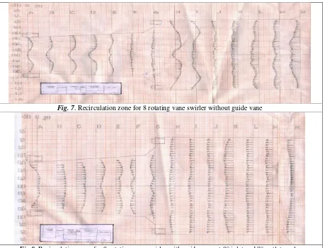
The axial, radial and tangential velocities are measured at various axial locations. At each axial location the five-hole pitot sphere is moved for measuring the various velocity components. The fig.7, fig.8 and fig.9 shows the axial velocity profiles from experimental values for eight rotating vane swirler without guide vane, eight rotating vane swirler with guide vane at 0° inlet and 0° outlet angle, eight rotating vane swirler with guide vane at 0° inlet & 45° outlet angle respectively. At station A in fig.7, it is found that the negative velocity exists only at the centre point which is mainly due to the presence of hub. The increase in the axial velocity is due to impart of kinetic energy to the moving fluid by the vane swirler. For eight vanes swirler, reverse velocity occurs from station A to station G in the Diffuser and maximum reverse velocity occurs is of 10 m/s. Maximum reverse velocity occurs from station K to O is 18 m/s in the expansion chamber. Entire or complete recirculation is occurring into the expansion chamber. Due to turbulence varying velocity is being observed in station H & I.
Fig.8, it is found that the positive velocity exists from station A to E in the diffuser region with maximum velocity 18 m/s. Maximum reverse velocity occurs from station F to O is 18 m/s in the expansion chamber. Entire or complete recirculation is occurring into the expansion chamber. At the exit of expansion chamber, pressure is greater than the atmospheric pressure.
Fig.9 Recirculation zone for 8 rotating vane swirler with guide vane at 0° inlet and 45° outlet angle
Fig.9, it is found that the entire negative velocity exists from station A to C, recirculation region is developing in diffuser region. At station D & E due to turbulence, varying velocity is being observed. At station F & G, again entire negative velocity is observed. In expansion chamber from station L to O entire reversal of flow if occurred. Due to turbulence velocity is varying in station H to K. A good mixing of the reactants with air occurs due to the high turbulence generated by high shear stresses.
VII. CONCLUSION
The experimental results provide the comparisons between rotating vane swirler and fixed swirler. It was found that complete recirculation zone in expansion chamber for rotating vane swirler while central recirculation zone is found in fixed vane swirler. Also uniform velocity flow is observed in rotating swirler with guide vane at 0° inlet and 0° outlet angle. Good recirculation zone is found in rotating swirler as compared to fixed swirler. The tailpipe provided at the downstream of the swirler is helpful in pressure recovery as the flow leave in the atmosphere. The measurement of axial, radial and tangential velocity helps to determine the mean flow field characteristics downstream of the swirler, which can be used for reacting flow studies in burners and combustors. As per this design, we are getting strong swirl number by experimental and theoretical calculation.
REFERENCES
[1]. Chigier, N.A., & Beer, J.M. 1964. Velocity and Static Pressure Distributions in Swirling Air Jets Issuing from Annular and Divergent Nozzles. Journal of Basic Engineering, 86, 788–796.
[2]. R ThundilKaruppa Raj & V Ganesan, Experimental study of recirculating flows induced by vane swirler, Indian Journal of Engineering & Material Sciences, Vol. 16, February 2009, pp. 14-22.
[3]. R. ThundilKaruppa Raj, V. Ganesan, Study on the effect of various parameters on flow development behind vane swirlers, International Journal of Thermal Sciences 47 (2008) 1204–1225 1205.
[4]. E.Kilik, Better Swirl Generation by using Curved Vanes, California State University, Long Beach, California..
[5]. M.L. Mathur, N.R.L. Maccallum, Swirling air jets issuing from vane swirlers. Part 1: free jets, Journal of the Institute of Fuel 214 (1967) 214– 225.
[6]. Mathur, M.L., &Maccallum, N.R.L. 1967. Swirling Air Jets Issuing from Vane Swirlers. Part 2: Enclosed Jets. Journal of the Institute of Fuel, June, 238–245.
Vol. 3, Issue 7, July 2014
[9] M.R.Pawar, A.S.Mohite, A.R.Patel, Investigation and Validation of swirl generation in Combustion chamber, ICAME,2010. SVNIT, SURAT. [10] Ashok K.Dhakiya, Bhavin K.Shah , Arvind.S.Mohite, Study of flow through combustion swirler with the effect of diffuser on the recirculation
zone. International Journal of Engineering Research and Development e-ISSN: 2278-067X, p-ISSN: 2278-800X, www.ijerd.com Volume 3, Issue 6 (September 2012), PP. 68-73