ISSN(Online): 2319-8753 ISSN (Print): 2347-6710
I
nternational
J
ournal of
I
nnovative
R
esearch in
S
cience,
E
ngineering and
T
echnology
(An ISO 3297: 2007 Certified Organization) Vol. 4, Issue 11, November 2015
Effect on Efficiency of Pulse Wheel/Flywheel,
when the Parameter ‘Time’ Is Considered
During Designing
Saurabh Vikas Chaudhari.
B.E. Student, Department of Mechanical Engineering, J.T.M.C.O. Engineering, Faizpur, Maharashtra, India.
ABSTRACT: Mechanical parameters such as power, RPM, torque, radius, length, weight, and time are considered during the designing of the every mechanism since the efficiency of the system is depend upon these parameters. These parameters are very important, and without considering them any system cannot be perfect. When it is illustrate that the efficiency of the pulse wheel/flywheel is unbounded by performing mathematical calculations that time, the parameter ‘Time’ for which power is to be transmitted from input shaft to output shaft is not considered. But after analysing constructional properties it is found that, parameter ‘Time’ is directly proportional to the ‘length of friction tooth’ and it must be taken into consideration during designing of pulse wheel/flywheel when the I.C. Engine assembly is required to be replaced by equal capacity pulse mechanism.
KEYWORDS: Efficiency, Time, Friction tooth Length, Design process, Pulse mechanism, I.C. Engine, Power pulse.
Note: For understanding detailed phenomena & methodology of pulse wheel/flywheel, refer the research paper titled 1] “pulse wheel/flywheel; the hidden science for developing technologies” from Vol. 4, Issue 9, September 2015 2] “Pulse Wheel/Flywheel; Contributing New Science for Unbounding Efficiency, to the Era of Physics!” from
Vol. 4, Issue 10, October 2015 of IJIRSET
I. INTRODUCTION
The pulse wheel/flywheel is the hidden or indirectly applied science behind the working of I.C. Engine. During the designing of the I.C. Engine, designer considers torque capacity of the engine, RPM of the output shaft, power output of the engine during running at designed RPM, stroke length of the piston, heat liberation through the overall system and total losses in the system due to moving parts of the mechanism. These all technical parameters affect the efficiency of the mechanism. As the pulse wheel/flywheel is born from I.C. Engine hence these parameters should be taken into consideration during the designing of the pulse wheel/flywheel, not all parameters but considerations of some parameters from all these parameter is unavoidable.
In this research paper I tried to explain the effect on the efficiency of the system, when the parameter ‘Time’ for which power is to be transmitted from input shaft to the output shaft of the pulse mechanism is considered i.e. time for which power wheel and pulse wheel/flywheel remains in contact. The impulsive power is transmitted through friction tooth in pulse mechanism, hence the Time for which the power is supplied from input shaft to output shaft of the mechanism and the Length of the friction tooth required for the impulsive power transmission process are directly proportional to each other.
This consideration of parameter Time is very important for designing when the previous assembled I.C. Engine in the system is want to be replaced by pulse mechanism having all the technical parameter equal to that of I.C. Engine. This research paper can contribute the help in the development of the pulse mechanism in which the pulse wheel/flywheel is used as main working component.
II. EXISTING WORK ON PULSE WHEEL/FLYWHEEL
ISSN(Online): 2319-8753 ISSN (Print): 2347-6710
I
nternational
J
ournal of
I
nnovative
R
esearch in
S
cience,
E
ngineering and
T
echnology
(An ISO 3297: 2007 Certified Organization) Vol. 4, Issue 11, November 2015
of piston in downward direction pushes the crank for certain degrees during every 720 degree rotation. This process tends to add a power impulsively to the flywheel which is attached to the engine shaft. By replacing the cylinder and crank arrangement with flywheel mounted with friction tooth on its circumference, we can directly add 2 power pulses (power equal to expansion stroke) to the flywheel in every 720 degree of its rotation. This replaced mechanism generates more power and torque than that of I.C Engine by consuming lesser amount of power than that of I.C. engine.
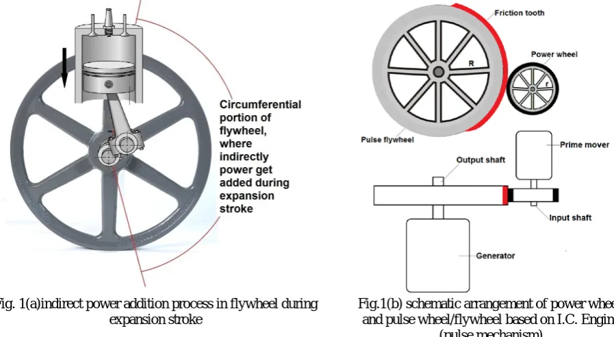
Fig. 1(a) describes the indirect energy addition process in flywheel, caused due to thrust produce on the surface of the piston during the expansion stroke of the engine.
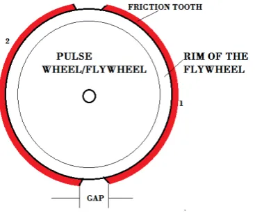
Fig: 1(b) describes the construction of the pulse wheel/flywheel based on the technical specification of I.C. Engine. The component name pulse wheel/ flywheel is collaborated name describes pulse wheel or pulse flywheel. There is difference of only weight between the pulse wheel and pulse flywheel; pulse wheel is light in weight and consist of base wheel and friction tooth(s), while pulse flywheel is heavy in weight and consist of base flywheel and friction tooth(s). Due to light weight, pulse wheel is used when there is need to transmit power only and due to heavy weight, pulse flywheel is used when there is need of power transmission as well as energy storage. To deliver a power pulse to the pulse flywheel as shown, power wheel is used and this power wheel is driven by prime mover. Prime mover can be electric motor. steam turbine or any device having rotating shaft. To convert induced power in output shaft generator is provided. The main advantage of using pulse mechanism is that it does not need to consume fossil fuel (as electric motor is used) but is still capable of providing equivalent power and gives more efficiency than that of I.C. Engine.
Fig. 1(a)indirect power addition process in flywheel during expansion stroke
Fig.1(b) schematic arrangement of power wheel, and pulse wheel/flywheel based on I.C. Engine
(pulse mechanism)
When it is illustrated that the efficiency for the pulse wheel/flywheel is unbounded performing mathematical calculations that time only two parameters were taken into consideration, these was torque and RPM. And it is assumed that “there is no need to consider the time for which the torque is applied on the crank rod by the connecting rod
during the expansion stroke. If parameter time is already taken in consideration during the designing of I.C. Engine, then it automatically get considered in specification and calculations of pulse wheel/flywheel”
ISSN(Online): 2319-8753 ISSN (Print): 2347-6710
I
nternational
J
ournal of
I
nnovative
R
esearch in
S
cience,
E
ngineering and
T
echnology
(An ISO 3297: 2007 Certified Organization) Vol. 4, Issue 11, November 2015
III. SCOPE OF RESEARCH
This research can helps in understanding the effect of consideration of parameter ‘Time’ during the designing of pulse wheel/flywheel on the efficiency of pulse mechanism or total system.
IV. BASICS OF I.C. ENGINE AND PULSE MECHANISM
[A] The I.C. Engine mechanism is the 4 stroke mechanism in which output shaft completes 720 degree rotation i.e. two complete rounds. This 720 degree rotation forms one complete cycle.
We have the formula to calculate the output power of the I.C. engine, HP = Torque (lb-ft) * RPM / 5252
I.e. the power developed due to total number of expansion strokes is getting considered in calculation of the output power of the engine. This means that total power developed in 720 degree rotation on the engine shaft is calculated for total gross output of the engine using this formula.
[B] The pulse wheel/flywheel is born from I.C. Engine and hence there are lots of similarities between I.C Engine and the pulse wheel/flywheel. But the difference is only that, in I.C. Engine when the power is applied on crank of the engine during the expansion stroke is called as “power stroke” and in Pulse mechanism when the power is applied on the first shaft (output shaft) through power wheel is known as “Power pulse”. When the pushing mechanism is completely designed by considering torque generated during the fuel blast of the I.C. Engine, with maintaining its appropriate RPM then, the power of power pulse and the power of power stroke are equal.
When the term “power of power pulse” is taken into consideration that time, this term includes both ‘Torque’ and ‘RPM’.
[C] There is strong relationship between the ‘Time’ required for piston to travel complete stroke length of I.C. Engine and the ‘length of Friction tooth’ of the pulse wheel/flywheel. When the pulse wheel/flywheel is to be design for same power output as that of I.C. Engine, that time with RPM and torque, controlling of the parameter ‘Time’ for which power wheel and pulse wheel/flywheel remains in contact through friction tooth, is very necessary. For less numbers of friction tooth, if the power is getting transmitted for short time, then it will take long pause for energy addition. This will reduce the power output of the system; due to such problem the other equipments connected to the output shaft of the pulse mechanism cannot work properly. Hence to avoid such output problems, ‘Time’ consideration is important.
V. CONSIDERATION OF PARAMETER ‘TIME’ DURING DESIGNING
[When the equal capacity pulse wheel/flywheel is to be design as that of considered I.C. Engine]
The ‘Time’ for which the torque is applied on the crank by the connecting rod during the expansion stroke is the important consideration for the designing of pulse wheel/flywheel, and this parameter ‘Time’ is depends upon the stroke ‘Length’ of the I.C. engine cylinder. The following Fig.2 shows the relation between the Stroke length, Time and angular displacement of crank.
ISSN(Online): 2319-8753 ISSN (Print): 2347-6710
I
nternational
J
ournal of
I
nnovative
R
esearch in
S
cience,
E
ngineering and
T
echnology
(An ISO 3297: 2007 Certified Organization) Vol. 4, Issue 11, November 2015
Fig.2: Relation between stroke length, time and angular displacement of crank
This means that, if the friction tooth having length nearly half of the circumference is fixed on pulse wheel/flywheel mounted on the output shaft of the pulse mechanism, then we can obtain ‘Time’ for which power is to be supplied to the pulse wheel/flywheel by power wheel, which will be same as that of the time for which piston applies torque on the crank rod of the I.C Engine, during expansion stroke. (useful for I.C. Engine having number of
cylinder less than or equal to 4)
Let us consider that, the I.C. Engine takes 4 sec. to complete one cycle of 720 degree rotation hence, to complete one 360 degree rotation it requires 2 sec and for 180 degree rotation i.e. for one stroke it takes 1 sec. from total considered time.
According to this assumption, during the expansion stroke (power stroke) the piston applies torque on the crank of the output shaft of the engine for 1 sec. As the pulse wheel is to be design considering the technical specification of the I.C Engine hence the power transmission process in pulse mechanism must be continue for 1 sec.
In pulse mechanism, the parameter ‘Time’ for which power is to be transmitted from input shaft to output shaft is totally depend on the friction tooth length. It means that Longer the friction tooth length, maximum the power transmission time.
If the parameter ‘Time’ is to be consider during the designing of the pulse wheel/flywheel when the designer has to consider multi cylinder I.C. Engine having more than 4 cylinders then, it becomes very difficult to obtain the length of friction tooth if we think about parameter ‘time’ and try to calculate it directly and also ‘Time’ consideration becomes very complicated and confusing for the designer.
The best method is, don’t think about parameter ‘time’ directly for which power is to be transmitted. We will take the characteristic constructional property of the pulse wheel/flywheel into consideration (as described in Fig.2), and will design accordingly.
[01]For single cylinder engine-
ISSN(Online): 2319-8753 ISSN (Print): 2347-6710
I
nternational
J
ournal of
I
nnovative
R
esearch in
S
cience,
E
ngineering and
T
echnology
(An ISO 3297: 2007 Certified Organization) Vol. 4, Issue 11, November 2015
Fig. 3: Actual power addition process in I.C. Engine cycle.
But the constructional problem is that in pulse mechanism we cannot apply power pulses less than 2 in complete 720 degree rotation where in I.C. Engine, there is only 1 power stroke get applied in complete 720 degree rotation.
Let, consider the Gross Output power of the engine = 100 HP. This consideration will help us to understand the construction of pulse wheel/flywheel when the parameter Time is to be considered during designing process.
As described in Fig. 4, we replace the I.C. Engine assembly with the pulse wheel/flywheel having two friction tooth(s) fixed on its circumference, where the both friction tooth(s) nearly covers half of the circumferential length (concluded from Fig.2) of the flywheel from right and left side, Also suitable Gap is kept between both friction tooth(s) for performing impulsive power addition process.
Fig. 4: pulse wheel/flywheel having 2 friction tooth(s)
(This arrangement of friction tooth(s) is applicable for 4 cylinders I.C. Engine also.)
Due to such arrangement of friction tooth on pulse wheel/flywheel in pulse mechanism, power will apply on the output shaft for 4 times in its complete 720 degree rotation, hence the power generated by the pulse mechanism will be 4 times greater than that of I.C. Engine. If we directly add the power pulse of 100 HP to the above designed pulse wheel/flywheel then it will give an output of 400 HP, but here we have assumed that the maximum output limit for design is 100 HP.
Hence,we reduce the input power of power pulse by 4 times i.e. 100 / 4 = 25 HP
Hence, the input power of power pulse should be 25 HP for the designed pulse wheel/flywheel.
(1) Suction stroke-
No power addition
(2) Compression stroke- No power addition
(3) Expansion stroke- Power addition
(4) Exhaust stroke-
ISSN(Online): 2319-8753 ISSN (Print): 2347-6710
I
nternational
J
ournal of
I
nnovative
R
esearch in
S
cience,
E
ngineering and
T
echnology
(An ISO 3297: 2007 Certified Organization) Vol. 4, Issue 11, November 2015
The advantage of dividing the required gross output by the number of power pulses which are getting delivered in complete 720 degree rotation is that, we easily obtain required output and the amount of power necessary for input of the mechanism, also indirectly the parameter ‘Time’ get achieved in construction of pulse wheel/flywheel.
In above calculation, we can also divide the power amount 100 HP by any number (except 1, 2&3) instead of 4 but, it will make us to change in length & number of friction tooth(s) of pulse wheel/flywheel according to that number. Due to this variation, it becomes difficult to maintain the parameter ‘Time’ during designing.
As the length of friction tooth is taken equal to the nearly half of the circumferential length of the flywheel on which it is mounted hence, parameter ‘Time’ for which torque is to be applied on the pulse wheel/flywheel is maintained same as that of time used by each stroke of I.C. Engine.
It should be note that, for maintaining the parameter ‘Time’, radius of the pulse wheel/flywheel does not
matter, but the RPM of first/output shaft of the pulse mechanism must be equal as that of considered I.C. Engine
[02]For Two & Four cylinder engine-
The method for construction of pulse wheel/flywheel is same as that of design procedure used for single cylinder engine.
[03] For multi cylinder engine having number of cylinder more than
4-Let us consider 12 cylinder 4 stroke I.C. Engine, which takes 24 sec. (it is only assumption) to complete one cycle of 720 degree rotation. There are 12 expansion strokes in one cycle hence 6 expansion strokes adds power in 1st half cycle and remaining 6 expansion stroke adds power in 2nd half cycle.
It means that 12 sec are getting used by 6 expansion strokes i.e. 2 sec for each expansion stroke, which is the equal time for each of the expansion stroke applied by that engine.
Hence, for construction of pulse wheel/flywheel, simply provide 6 friction tooth(s) of equal length on its circumference with the equal appropriate gap between two adjacent friction tooth(s). [The gap between two adjacent friction tooth(s) should not large; otherwise it will take long pause for energy addition as compare to that of I.C.
Engine.]. Fig. 5: describes the arrangement of the equal length friction tooth(s) on the circumference of pulse
wheel/flywheel for considered 12 cylinder I.C. Engine.
Fig. 5: Six toothed pulse wheel/flywheel having equal friction tooth length
i.e. No. of power pulses in 1st 360 degree rotation = 6, No. of power pulses in 2nd next 360 degree rotation = 6
And Total no. of power pulses will be added in pulse wheel/flywheel = 6 + 6 =12 i.e. power output equal to that of considered I.C. Engine will be obtain.
As we keep the RPM of the first/output shaft of pulse mechanism equal to the RPM of the considered I.C. Engine, hence each friction tooth will remain in contact with the power wheel for 2 sec (as we considered)
Procedure to obtain the length of friction tooth for multi cylinders engines having more than 4 cylinders:-
[step 1] Calculate the total outermost circumferential length of the available flywheel using formula Circumference, C = 2*Π*R
[step 2] Value of X i.e. number of friction tooth(s) is determined by the formula
𝐗𝐗 =𝐍𝐍𝟐𝟐
ISSN(Online): 2319-8753 ISSN (Print): 2347-6710
I
nternational
J
ournal of
I
nnovative
R
esearch in
S
cience,
E
ngineering and
T
echnology
(An ISO 3297: 2007 Certified Organization) Vol. 4, Issue 11, November 2015
N = Number of Cylinders/Piston present in the I.C. Engine, which is considered for the construction of pulse wheel/flywheel.
2 = constant. Since the formula HP = Torque * RPM / 5252 covers total power added in 2 complete rotations of the shaft.
[step 3] Take the suitable length for Gap which is to be keep between two adjacent friction tooth(s) i.e. G [step 4] Substitute the values in the formula
C = X * (L + G)
i. e. 𝐋𝐋= [ 𝐂𝐂/ 𝐗𝐗 ] − 𝐆𝐆
Where,
C = Total length of circumference of the flywheel L = length of friction tooth
X = Number of friction tooth(s)
G = Distance / Gap between two adjacent friction tooth(s)
The above design procedure is same for every even numbered multi cylinder engine having number of cylinders more than 4, when the designer strictly want to design the pulse wheel/flywheel by considering technical parameters ‘Time’ of I.C. Engine.
Including above described procedure, now we have two methods to design pulse wheel/flywheel: (A) Without considering I.C. Engine parameters ‘Time’, for which power is to be transmitted.
(B) By considering parameter ‘Time’
The main difference between both the procedures is that, in procedure (A) first we decide length of friction tooth and the length of Gap to be kept and then we calculate required circumference of the base flywheel on which friction tooth(s) will be fixed. And in procedure (B), first we measure the total available length of circumference of the flywheel and decide the length of Gap and after this we calculate the length of friction tooth.
By using procedure (B) we can easily maintain same ‘Time’ for which power is to be transmitted, as that of corresponding I.C. Engine.
VI. THE EFFECT OF PARAMETER ‘TIME’ ON EFFICIENCY, WHEN IT IS MAINTAINED BY CONTROLLING THE FRICTION TOOTH LENGTH
First we assume a reference ground for the easy of observation-
We will design a pulse wheel/flywheel having power generating capacity of 200 HP. During this designing process we will change only the number of cylinders present in the I.C. Engine to design pulse wheel/flywheel accordingly, and then we will observe its effect on efficiency.
Assumption: The power of each power pulse is assumed constant.
ISSN(Online): 2319-8753 ISSN (Print): 2347-6710
I
nternational
J
ournal of
I
nnovative
R
esearch in
S
cience,
E
ngineering and
T
echnology
(An ISO 3297: 2007 Certified Organization) Vol. 4, Issue 11, November 2015
[01] For 4 stroke, 6 cylinder engine-
Assumed Gross output power = 200 HP
Number of power pulses = 6 (in 720degree rotation) Hence,
200 HP / 6 = 33.33 HP
i.e. if the power pulse having power 33.33 HP is applied on pulse wheel/flywheel for 6 times in complete 720 degree rotation, the gross output will be 200 HP
Input power of power pulse = 33.33 HP
Efficiency Ƞ=𝑜𝑜𝑜𝑜𝑜𝑜𝑜𝑜𝑜𝑜𝑜𝑜 𝑜𝑜𝑜𝑜𝑝𝑝𝑝𝑝𝑝𝑝 𝑖𝑖𝑖𝑖𝑜𝑜𝑜𝑜𝑜𝑜 𝑜𝑜𝑜𝑜𝑝𝑝𝑝𝑝𝑝𝑝 ∗ 100
Substituting values,
Ƞ =33.33 ∗33.33 ∗ 1006
=600 %
:Schematic diagram for 4 stroke, 6 cylinder engine
Here,
No. of power pulses in 1st 360 degree rotation = 3 No. of power pulses in 2nd next 360 degree rotation =3 Total no. of power pulses (i.e. expansion strokes) = 6
[02] For 4 stroke, 12 cylinder engine-
Assumed Gross output power = 200 HP
Number of power pulses = 12 (in 720degree rotation) Hence,
200 HP / 12 = 33.33 HP
i.e. if the power pulse having power 16.66 HP is applied on pulse wheel/flywheel for 12 times in complete 720 degree rotation, the gross output will be 200 HP
Input power of power pulse = 33.33 HP
Efficiency Ƞ=𝑜𝑜𝑜𝑜𝑜𝑜𝑜𝑜𝑜𝑜𝑜𝑜 𝑜𝑜𝑜𝑜𝑝𝑝𝑝𝑝𝑝𝑝 𝑖𝑖𝑖𝑖𝑜𝑜𝑜𝑜𝑜𝑜 𝑜𝑜𝑜𝑜𝑝𝑝𝑝𝑝𝑝𝑝 ∗ 100
Substituting values,
Ƞ =16.66 ∗ 1216.66 ∗ 100
=1200 %
:Schematic diagram for 4 stroke, 12 cylinder engine
Here,
ISSN(Online): 2319-8753 ISSN (Print): 2347-6710
I
nternational
J
ournal of
I
nnovative
R
esearch in
S
cience,
E
ngineering and
T
echnology
(An ISO 3297: 2007 Certified Organization) Vol. 4, Issue 11, November 2015
[03] For 4 stroke, 16 cylinder engine-
Assumed Gross output power = 200 HP
Number of power pulses = 16 (in 720degree rotation) Hence,
200 HP / 16 = 12.50 HP
i.e. if the power pulse having power 12.50 HP is applied on pulse wheel/flywheel for 16 times in complete 720 degree rotation, the gross output will be 200 HP
Input power of power pulse = 12.50 HP
Efficiency Ƞ=𝑜𝑜𝑜𝑜𝑜𝑜𝑜𝑜𝑜𝑜𝑜𝑜 𝑜𝑜𝑜𝑜𝑝𝑝𝑝𝑝𝑝𝑝 𝑖𝑖𝑖𝑖𝑜𝑜𝑜𝑜𝑜𝑜 𝑜𝑜𝑜𝑜𝑝𝑝𝑝𝑝𝑝𝑝 ∗ 100
Substituting values,
Ƞ =12.50 ∗ 1612.50 ∗ 100
=1600 %
:Schematic diagram for 4 stroke, 16 cylinder engine
Here,
No. of power pulses in 1st 360 degree rotation = 8 No. of power pulses in 2nd next 360 degree rotation =8 Total no. of power pulses (i.e. expansion strokes) = 16
[04] For 4 stroke, 50 cylinder engine-
*In actual it is very complicated to manufacture the I.C. Engine having 50 cylinders, but due to characteristic constructional property of the pulse wheel/flywheel 50 power pulses can be added to it, in complete 270 degree rotation.
Assumed Gross output power = 200 HP
Number of power pulses = 50 (in 720degree rotation) Hence,
200 HP / 50 = 4 HP
i.e. if the power pulse having power 4 HP is applied on pulse wheel/flywheel for 50 times in complete 720 degree rotation, the gross output will be 200 HP
Input power of power pulse = 4 HP
Efficiency Ƞ=𝑜𝑜𝑜𝑜𝑜𝑜𝑜𝑜𝑜𝑜𝑜𝑜 𝑜𝑜𝑜𝑜𝑝𝑝𝑝𝑝𝑝𝑝 𝑖𝑖𝑖𝑖𝑜𝑜𝑜𝑜𝑜𝑜 𝑜𝑜𝑜𝑜𝑝𝑝𝑝𝑝𝑝𝑝 ∗ 100
Substituting values,
Ƞ =4 ∗ 504 ∗ 100
=5000 %
The pulse wheel/flywheel with such a large number of friction tooth(s) is difficult to design and also it is very complicate to construct.(the assumed example of multi cylinder engine is only for calculation purpose)
Here,
No. of power pulses in 1st 360 degree rotation = 25 No. of power pulses in 2nd 360 degree rotation = 25 Total no. of power pulses (i.e. expansion strokes)= 50
From the above result of calculations, it is observed that, there is no special effect on the efficiency of the pulse wheel/flywheel of consideration of parameter ‘Time’ during its designing process; the efficiency remains unbounded, but due to time consideration, the designing procedure of pulse wheel/flywheel gets change. The ‘Time’ consideration has importance only when the equal capacity pulse wheel/flywheel is to be designed strictly as that of considered I.C. Engine, but has no mean when the pulse wheel/flywheel is required to be design by considering all new parameters, where all parameters are free from limits i.e. during complete new designing.
ISSN(Online): 2319-8753 ISSN (Print): 2347-6710
I
nternational
J
ournal of
I
nnovative
R
esearch in
S
cience,
E
ngineering and
T
echnology
(An ISO 3297: 2007 Certified Organization) Vol. 4, Issue 11, November 2015
not be constructed according to that of I.C. Engine which is want to be replace, but it will constructed according to equal capacity multi cylinder engine having number of cylinders more than replaced I.C. Engine, and also the parameter ‘Time’ will be maintain during construction).
VII. OPTIONAL ARRANGEMENT FOR PULSE MECHANISM
It observed that, it is very difficult to construct the pulse flywheel as the number of friction tooth goes increasing, hence here we can use a pulse wheel having less number of friction tooth(s) for power input purpose i.e.
pulse wheel will be provided to the input shaft, this modification in arrangement does not affect the efficiency but it will solve the constructional complications related to pulse flywheel. The phenomena of impulsive power addition remain same in this type of arrangement.
The following Fig. 6 describes the optional arrangement for the pulse mechanism when the pulse flywheel become difficult to construct due to mounting requirement of large number of friction tooth(s) on its circumference. It comprises of rimmed disk flywheel having uniform and continuous friction surface (material) provided on its complete circumferential length where it is mounted on the output shaft of the pulse mechanism. The small size pulse wheel having less numbers of friction tooth(s) is mounted on input shaft of the mechanism; here the pulse wheel is used for power input purpose as shown.
Fig. 6: optional arrangement for Pulse mechanism
As the pulse wheel is used for power input purpose we can add large number power pulses in one rotation of output shaft as compare to construction in which pulse wheel is mounted on output shaft of the mechanism for power generating purpose. Even in this type of arrangement the pulse wheel is mounted on the input shaft of the pulse mechanism, the design procedure for it remains same. The procedure of considering radial ratio of pulse wheel and flywheel mounted on output shaft of the mechanism is same as the procedure used for arrangement described in Fig. 1(b). But due to mounting of pulse wheel on input shaft calculations get change.
Advantages of optional arrangement of pulse mechanism over the arrangement described in Fig. 1(b):
[01] This arrangement has one advantage over the arrangement shown in Fig. 1(b) is that, it requires less number of friction tooth(s) and hence the maintenance time required for replacement of worn friction tooth(s) is less. [02] For high RPM pulse mechanism this arrangement is most suitable as the vibrations generating during the
meeting of friction tooth and regular friction surface are of small intensity. [03] This arrangement of pulse mechanism is suitable for high speed working systems.
[04] The maintaining and checking of friction tooth thickness becomes easy due to less number of friction tooth(s). [05] Due to such type of arrangement compact construction of pulse mechanism is possible.
VIII. CASE STUDY
ISSN(Online): 2319-8753 ISSN (Print): 2347-6710
I
nternational
J
ournal of
I
nnovative
R
esearch in
S
cience,
E
ngineering and
T
echnology
(An ISO 3297: 2007 Certified Organization) Vol. 4, Issue 11, November 2015
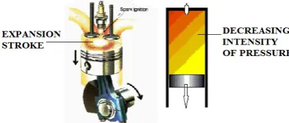
found that the piston moves with constant velocity throughout the complete stroke length, even when the piston reaches close to BDC the intensity of pressure applying by hot gases is weak. This constant velocity attained by the piston during its downward reciprocating motion is due to momentum of the weight of the piston and the kinetic energy stored in flywheel due to impulsive power addition during fuel blast. It means that, near about 10 % - 15% (or more) of the total stroke length of the cylinder is travelled by the piston at the end of expansion stroke, due to only previously gained kinetic energy.
Fig. 7 describes the gradual decrease in pressure intensity of the hot gases acting on the piston head, when the piston moves toward BDC from TDC. From the described figure we can see that, at the end of expansion stroke the intensity of pressure generated by hot gases is weak as compare to intensity of pressure present at the top portion of the cylinder.
Fig.7: Decreasing intensity of pressure during expansion stroke
If one wants to consider the effect of pressure intensity acting on piston head to perfectly finding of the parameter ‘time’ for which the piston applies torque on the crank during expansion stroke for the designing of pulse wheel/flywheel, then he/she must note that, for designing of pulse wheel/flywheel the angular displacement of the crank is taken into consider hence the consideration of pressure intensity for finding friction tooth length is not needed. The plus point of pulse mechanism over I.C. Engine is that, in I.C. Engine the power (applying pressure intensity) of power stroke goes decreasing as the piston starts to move in downward direction, but in pulse mechanism the power of power pulse remains uniform throughout the total friction tooth length.
Even consideration of pressure intensity is not so useful for finding required friction tooth length, but it will definitely help to decide or tally the length of Gap present between two adjacent frictions tooths because length of Gap decides the pause time between to consequent power pulses. If the pause time between two consequent power pulses is long then it will reduce the power output of the pulse mechanism, and if the pause time between two consequent power pulses is very small then it will strongly affect on the power pulse addition phenomena.
The flowing Table 1 contains the suitable limits for the length of Gap in percentage of the total length of friction tooth, for the better performance of pulse wheel/flywheel.
Table 1: Percentage limits for the length of Gap to be kept between two adjacent friction tooth(s)
Sr. No. Condition Limit (%)
1. When the uniform pressure intensity is considered 15 to 30 2. When the non uniform pressure intensity is considered 30 to 40
ISSN(Online): 2319-8753 ISSN (Print): 2347-6710
I
nternational
J
ournal of
I
nnovative
R
esearch in
S
cience,
E
ngineering and
T
echnology
(An ISO 3297: 2007 Certified Organization) Vol. 4, Issue 11, November 2015
IX. DESIGNATED RESULTS
[01] The consideration of parameter ‘Time’ during designing process of pulse wheel/flywheel hasnot any special effect on its efficiency, but this consideration helps in easy construction of equal capacity pulse wheel/flywheel as that of considered I.C. Engine.
[02] The Time for which the power is to be supplied from input shaft to output shaft of the pulse mechanism and the
Length of the friction tooth required for the impulsive power transmission process are directly proportional to each other.
[03] For same capacity output, if the number of power pulses increases, overall efficiency of the system increases. [04] Due to Time consideration, the power pulse having power equal to power stroke of considered I.C. Engine can
be generate with higher accuracy.
[05] By providing pulse wheel/flywheel on the input shaft of the pulse mechanism, the capacity of addition of power pulses in one rotation get increases i.e. large number of power pulses can be added in single rotation.
[06] In I.C. Engine, the intensity of pressure generated due to formation of hot gases during the expansion stroke i.e. power stroke, start decreasing as the piston starts to move towards BDC, but in pulse mechanism the intensity of power pulse remains constant throughout total length of friction tooth.
[07] The design process of pulse wheel/flywheel changed completely due to consideration of parameter ‘Time’, but this obtained design process is very flexible and it is applicable on any available circumference of the flywheel.
X. CONCLUSION
By suitably controlling the friction tooth length we can easily maintain the parameter ‘Time’ for which power is to be transmitted from input shaft to the output shaft in pulse mechanism. When the output of the pulse mechanism is bounded by limits, only then ‘Time’ consideration is important during designing of pulse wheel/flywheel, but where the output is not defined, there this consideration is not so important.
REFERENCES
[01] Willard W Pulkrabek. “Internal Combustion Engines”, Pearson Education. [02] Domkundwar, ., “Internal Combustion Engines”, Dhanpat Rai & Co. New Delhi. [03] Shyam K. Agrawal, “Internal Combustion Engines”, New Edge International Publication. [04] K.K. Ramalingam, “Internal Combustion Engines”, Scitech Publication.
[05] V. Ganeshan, “Internal Combustion Engines”,2/E, Tata Mcgraw Hill, New Delhi.
[06] E. F. Obert , “Internal Combustion Engines And Air Pollution”, Harper And Row, New York.
[07] Shigley J.E. And Mischke C.R., “Mechanical Engineering Design”, Tata Mcgraw Hill Publication Co. Ltd. [08] Juvinal R.C., “Fundamentals Of Machine Components Design”, John Wiley And Sons.
[09] Patrick J. Kelly “Gravity-Powered Systems” From A Practical Guide To Free-Energy Devices. [10] Chas Champbel’s System.
BIOGRAPHY