The hardware used in the AXE system has been updated continuously. Initially, all telephony-related hardware in AXE was ana-logue. Over the years, almost all hardware has been redesigned to take advantage of the formidable advances in electronics. This has been a continuous, ongoing process. Digi-talisation was gradually introduced in the early 1980s, followed by application-specific integrated circuits (ASIC) in the mid-1980s. A major breakthrough came in 19861. In the late 1980s and early 1990s, the
evolution continued in small steps. A few original products have remained, however. Today, these last remaining products are being replaced. At the same time, almost all other hardware products that make up the basic AXE system are being rationalised.
AXE hardware evolution
Urban Hägg and Tomas Lundqvist
The AXE system is the most widely deployed switching system in the world. It is used in public telephony-oriented applications of every type, including traditional fixed network applications in local, transit, international and combined networks. AXE is also deployed for all major mobile standards – analogue as well as digital. AXE is very strong in intelligent networks and other real-time database applications. Recent designs also enable data communication capabilities to be added to the system.
From its inception, the AXE system was designed to accommodate con-tinuous change. Throughout the years, new applications have been intro-duced, its array of functions has grown, and its hardware has been steadily updated.
The authors describe how the latest advances in hardware technology have been brought into the system, thereby dramatically improving such charac-teristics as floor space, power consumption, system handling, and cost of ownership. As always, backwards compatibility has been maintained to the greatest possible extent, in order to protect previous investments in AXE.
DL2
DLMUX
APT dev TSM-DL3
DL3 DL1
DL2
APT dev
RP4 RP RP
RP RPB-S
RPH-S RPH
IOG CP
Generic device magazine
AXE evolution
ExtensionsGSS64K
RPB-P
DL2
DLMUX
APT dev
DL3 DL2
APT dev
RP4 RP4 RP
RPB-S
RPH-S RPH-P
CP Generic device
magazine
GSS64K
AXE evolution
New deliveries
DL3
DLMUX
DL_IO DL2
Generic device magazine or BYB 202 equipment
RPV2
RPB-P
IOG20 Figure 1
Architecture
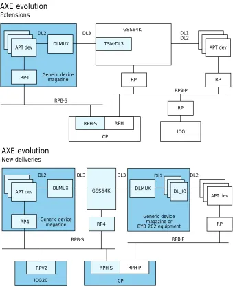
As the AXE system continues to evolve, sys-tem designers ensure that the very solid and proven system architecture is maintained. The fundamental principle of a central pro-cessor (CP) that controls regional propro-cessors (RP), which in turn control hardware ser-vices, has proved to be superior. Strict in-terfaces ensure that different system com-ponents can be developed independently. To ensure non-stop operation, all vital traffic and operation and maintenance (O&M) sys-tem products are built in duplicated struc-tures.
In order to fully exploit the advantages of modern electronics, some fundamental sys-tem hardware interfaces are now being im-proved and extended. It goes without say-ing that compatibility is maintained in AXE.
Traditionally, a parallel bus, or a region-al processor bus (RPB), has been used for communication between the central and re-gional processors. Now, however, in order to increase capacity (data transfer rate) and
to decrease the need for interface hardware, a serial bus is being introduced alongside the existing RPB (Figure 1). The new RPB permits single-board regional processors to be housed in the same subrack as the devices they control, thus minimising hardware and cable interconnections between hardware devices.
In earlier generations of AXE, an ex-tension module (EM) bus and cables were used to connect regional processors to ap-plication hardware (extension modules). In the new hardware design, however, most re-gional processors are located in the same subrack as the extension modules they con-trol. By locating the regional processors in this way, designers have all but eliminated the EM bus, except in the backplane. The new location makes it much easier for operators to install and extend equipment. The traditional AXE interface (called the digital link 2, DL2) between the group switch (GS) and its connected devices was at the 2 Mbit/s primary multiplexing pulse code modulation (PCM) level.
Now, a new high-speed interface is being
ALI Alarm interface
ANSI American National Standards Institute
ASIC Application-specific integrated circuit
AST-DR-V3 Announcement service terminal version 3
ATM Asynchronous transfer mode BGA Ball grid array
BM Building module (1 BM=40.64 mm)
BSC Base station controller CANS Code answer
CCD Conference call device
CMOS Complementary metal-oxide semi-conductor
CP Central processor CSFSK Code sender for FSK tones CSK Code sender for DTMF tones CSR Code sender/receiver D-AMPS Digital AMPS
DL2 Digital link interface 2 DL3 Digital link interface 3 DSP Digital signal processor DTMF Dual-tone multifrequency E0 64 kbit/s digital link E1 2 Mbit/s digital link ECP 303 Echo canceller in pool
generation 3
ECP 404 Echo canceller in pool generation 4
EM Extension module EMB Extension module bus EMC Electromagnetic compatibility EMI Electromagnetic interference ETC5 Exchange terminal circuit
generation 5
ETSI European Telecommunications Standards Institute
FSK Frequency shift keying
GDM Generic device magazine (sub-rack)
GS Group switch
GSM Global system for mobile commu-nication
GSS Group switch subsystem HLR Home location register IN Intelligent network I/O Input/output IOG11 I/O system 11 IOG20 I/O system 20 IP Internet protocol
ISDN Integrated services digital network ITU-T International Telecommunication Union - Telecommunications Stan-dardization Sector
IWU Interworking unit KRD Keyset receiver device LED Light-emitting diode LUM Line unit module MSC Mobile switching centre MTBF Mean time between failures
MW Megaword
O&M Operation and maintenance PCM Pulse code modulation PDC Pacific digital cellular
PROM Programmable read-only memory PSTN Public switched telephone network RAM Random access memory RMS Remote measurement subsystem ROM Read-only memory
RP Regional processor
RP4 Regional processor generation 4 RPB Regional processor bus RPD Regional processor device RPG Regional processor with group
switch interface
RPV Regional processor connected to VME
SCP Service control point
SCSI Small computer system interface SNT Switching network terminal SPM Space switch module STC Signalling terminal central STM Synchronous transfer mode STP Signalling transfer point T1 1.5 Mbit/s digital link TCD Trunk continuity check device TSM Time switch module
TSM-1 155 Mbit/s time switch module VME Versa Module Eurocard
introduced at the third level in the basic PCM hierarchy. The interface, which is called DL3 (digital link 3), works at the 32 Mbit/s level (overhead excluded).
The introduction of the DL3 interface dra-matically decreases group switch and device hardware. Equally important, it removes massive amounts of internal system cabling. The DL2 interface has been retained to en-sure compatibility.
Each DL3 interface contains 16 multi-plexed DL2 interfaces. In fact, the DL2s run in the backplane of the new device subracks, which means that only one sixteenth of the cabling is needed between the group switch and the devices that are connected to it.
Basic technology
In general, designers taking part in the AXE hardware evolution programme have used ASICs, high-performance microprocessors, digital signal processors (DSP) and faster in-terfaces to improve AXE hardware. ASICs were chosen where volumes of circuits are very high or where performance is critical. Commercial microprocessors, which are be-coming commonplace for more and more applications, have also been integrated into the hardware. These changes allow design-ers to integrate commercial operating sys-tems and software – especially at the re-gional processor level.
Also, inasmuch as the processing capaci-ty of regional processors has kept pace with developments in general-purpose processor technology, the new AXE hardware requires fewer processors than were used before. This was another important factor in reducing the size of the exchange.
The most common type of processor in AXE systems today is the digital signal pro-cessor. DSPs, which are used in many kinds of application, are flexible platforms that may easily be programmed to provide new functions. Moreover, software at the DSP level may be sourced from other manufac-turers, which allows designers to introduce new functionality with shorter time to mar-ket.
Today almost all AXE hardware uses a 3.3 V power supply. This change and the use of submicron technology (0.25-0.5 µm) have reduced power consumption to levels far below that of previous hardware genera-tions.
Equipment practice
Owing to the introduction of high-speed in-terfaces and tougher requirements for elec-tromagnetic compatibility (EMC), AXE hardware designers constructed a new equipment practice, called the BYB 5012.
The BYB 501 has excellent EMC character-istics and fulfils Class B requirements with good margin. Compared with the BYB 202, whose cabinet shields against electromag-netic interference (EMI), the new equip-ment practice provides shielding at the sub-rack level. Note: the standard on which the BYB 501 is based uses the term subrack. However, in AXE terminology, the word magazine is often used.
The equipment practice supports point and single-point earthing. The
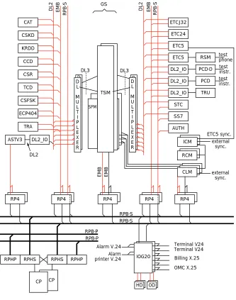
multi-D L M U L T I P L E X E R D L M U L T I P L E X E R CAT CSKD KRDD CCD CSR TCD CSFSK ECP404 TRA ASTV3 ETCJ32 ETC24 ETC5 ETC5 DL2_IO DL2_IO DL2_IO STC SS7 AUTH DL2_IO ICM RCM CLM
RP4 RP4 RP4 RP4 RP4
external sync. external sync. ETC5 sync. test phone test instr. test instr. RSM PCD-D PCD TRU
RPHP RPHS RPHS RPHP
CP CP Terminal V24 Terminal V24 Billing X.25 OMC X.25 Alarm V.24 Alarm printer V.24 OD HD IOG20 RPB-P RPB-P TSM DL3 DL3 D L M U L T I P L E X E R D L M U L T I P L E X E R SPM RPB-S RPB-S DL2 DL2 EMB RPB-S DL2 EMB RPB-S GS EMB EMB Cable Backplane Figure 2
point earthing concept will be used in all new AXE deliveries. The equipment prac-tice also supports several different sizes of board and cabinet. However, for use with AXE, two main board sizes are used: 115 x 175 mm, and 265 x 175 mm. The standard dimensions of the cabinet are as follows: Height: 1800 mm
Width: 600 mm Depth : 400 mm
Normally, no backplane cabling is needed on the subracks. Consequently, the cabinets may be placed back-to-back, giving the ex-change a very small footprint and allowing a flexible cabinet arrangement against walls. The cabinets will also be delivered fully equipped, their hardware tested and cabled at the factory – a feature that greatly reduces installation time and other time-to-customer-related activities.
Group switch
The group switch3has been the subject of
far-reaching rationalisation. For example, a configuration for 65,536 group switch ports is now contained in two cabinets (Figure 3). What is more, the new group switch consumes 95% less power than its predecessor. Nevertheless, the basic struc-ture of the switch – that is, the time-space-time (T-S-T) switching architecture, the time switch, the space switch, the clock module, and system concepts such as the switching network terminal maintenance (SNT) and DL2 hardware interface – has been maintained, which facilitates hard-ware and softhard-ware design and preserves compatibility.
In improving the group switch, designers made the following changes:
• A 32 Mbit/s DL3 interface replaces six-teen 2 Mbit/s DL2 switch interfaces. • Four time switch module (TSM) functions
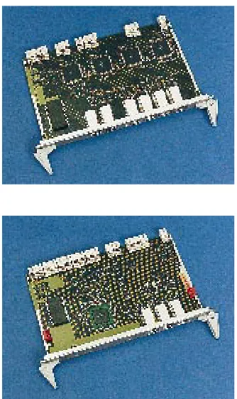
are grouped onto one board, yielding 2,048 ports per board (Figure 4). • A space switch module (SPM) function for
16,384 ports now fits on a single board (Figure 5).
• Switching equipment and the RPs that control the equipment are co-located in the same subrack.
These design changes gave rise to a switch subrack that contains eight TSM boards, providing a total of 16,384 switch ports; one SPM board; and four RP boards. Since the switch is duplicated, another plane is locat-ed in a second subrack with exactly the same configuration.
Some mobile systems employ subrate switching to handle bit rates below 64 kbit/s (8 kbit/s; 16 kbit/s; 24 kbit/s ... 64 kbit/s). In its maximum configuration, which has 4,096 ports, the subrate switch is housed in two small subracks: the A-plane is located in one subrack and the B-plane is located in the other.
As in earlier versions of the group switch subsystem (GSS), wideband (n x 64 kbit/s) is supported up to 2 Mbit/s.
The synchronisation equipment, which occupies another two small subracks, con-sists of:
16K plane A
16K plane A
16K plane B
16K plane B
16K plane A
16K plane A
16K plane B
16K plane B CLM, RCM
The 64K group switch
Figure 3
The new group switch in a 64K configuration, including synchronisation equipment.
Figure 4
The new time switch module board, which contains 2,048 ports, replaces four BYB 202 subracks.
Figure 5
• three clock modules;
• two highly accurate reference clock mod-ules;
• two incoming clock reference boards (for connecting additional clock references); • regional processors for controlling the
synchronisation equipment.
Designers have also constructed a compact switch subrack for switching applications that require less than 4,096 ports. This sub-rack contains a 4,096-port switch, three clock boards for synchronisation, 1,024 ports for subrate data transfer, and regional processors for controlling the equipment. The two switch planes are co-located in one subrack.
The new group switch was designed to provide backward compatibility. Accord-ingly, a DL3-to-DL2 converter subrack has been developed. The converter connects hardware that uses a DL2 cable interface to a new switch that uses the DL3 interface. Another way of connecting an old switch to hardware that uses the new DL3 interface is to add an interface board (which supports a DL3 cable interface) in existing TSM64C subracks.
The new design concept also allows the GSS switch to be extended to up to 131,072 ports.
Central processor
Designers of the AXE central processor have always emphasised high processing capaci-ty. This holds true even today. Nonetheless, while developing the next generation high-capacity central processor (APZ 212 30), AXE designers also produced a smaller, power-efficient processor (APZ 212 25) for switching applications that require moder-ate processing capacity.
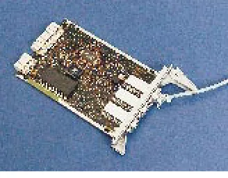
The APZ 212 25 has a very small foot-print (Figure 6) and consumes only 75 W of power. Designers reduced power consump-tion by replacing the 5 V supply voltage with 3.3 V, and by using 0.5 µm comple-mentary metal-oxide semiconductor (CMOS) ASIC technology with ball grid array (BGA) packaging. The maximum memory capacity of the APZ 212 25 is 64 Megawords (MW), program store; and 256 MW, data store. Despite its small size, this computer processor is 1.5 to 1.7 times more powerful than its much larger prede-cessor, the APZ 212 11.
Although it was designed for use in the BYB 501, where it uses the serial RP bus, the APZ 212 25 is fully compatible with the
parallel bus used in earlier versions of AXE switching equipment. In a minimum con-figuration, the APZ 212 25 may connect four of the new serial RP buses, controlling up to 128 regional processors. If more re-gional processors are required, or if parallel and serial RP buses must be used simulta-neously, then extension subracks may be added that allow up to 512 regional proces-sors to be connected.
Regional processors
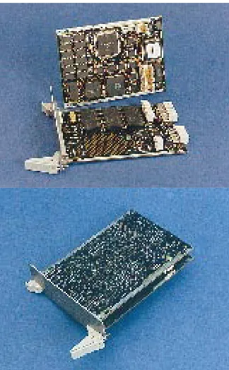
A new regional processor, called the RPG (regional processor with group switch in-terface, Figure 7) has been introduced for ap-plications that require high processing ca-pacity. Most applications that previously ran on the regional processor device (RPD – Motorola 68020) have been transferred to the RPG, which has at least four times as much processing capacity as the RPD. The RPG is a single-board processor based on the general-purpose Motorola 68060 run-ning at 50 MHz. On the same board is a communications processor (a Motorola 68360) for handling the switch interface and a 10 Mbit/s Ethernet interface. Although it may be used for any application that requires high processing power, the RPG will ini-tially be used with the following applica-tions:
• signalling system no. 7 – signalling ter-minal according to ANSI;
• signalling system no. 7 – signalling ter-minal according to ITU-T;
• signalling terminal central (STC) – sig-nalling terminal for base stations and re-mote subscriber switches;
• transceiver handler – base station sig-nalling in GSM;
• authentication in all mobile systems; • integrated services digital network
(ISDN) Internet access server (IP routing function).
In AXE, the RPG is the platform for hand-ling packet switched data communication. With respect to traffic handling, these types of regional processor have a more indepen-dent role, relative to the CP, than traditional AXE regional processors.
A new version of the traditional regional processor, called RP4 (regional processor generation 4), is used for controlling exten-sion modules. The RP4 is compatible with earlier versions of the regional processor. A prime benefit of the RP4 is that it is co-located in a subrack with the extension mod-ules it controls. This design does away with
Figure 6
The APZ 212 25 occupies only half a subrack in the BYB 501.
Figure 7
a large amount of cable, reduces size, and simplifies equipment handling consider-ably.
Earlier versions of the central processor may not be connected to new hardware with-out first modifying their side of the RP bus interface.
The regional processor bus interface VME (RPV) is a conversion product for the con-nection from the CP to the Versa Module Eurocard-based IOG20, through the RP bus. There are two RPVs: the first, known simply as RPV, is used for the parallel bus connection; the second, called the RPV2, is used for the serial bus connection.
IOG20, the AXE I/O
system
A duplicated input/output (I/O) system, known as the IOG20, handles data transport to and from an AXE exchange. Communi-cation to and from the AXE I/O system may be broken down into customer administra-tion and element handling.
The IOG20 is much smaller than the IOG11 – the previous generation I/O sys-tem. For example, whereas the IOG11 fills a whole cabinet in the BYB 202 equipment practice, the IOG20 fits into a single
sub-rack. Moreover, the IOG20 outperforms the IOG11 by as much as four to five times but consumes only one third as much power.
The new I/O system, whose design is char-acterised by modern technology and greater integration, contains relatively few printed circuit board types (seven instead of 25). In taking steps to make the system open to commercially available components, de-signers used the industry standards Versa Module Eurocard (VME) bus, Ethernet, and small computer system interface (SCSI). Similarly, they implemented Ethernet for connections between nodes and as a line in-terface. The IOG20 is currently available in three configurations:
• IOG20 – a fully compatible version of the twsubrack configuration with an in-terface to a parallel RP bus;
• IOG20B – a twin-subrack version with one node in each subrack (maximum con-figuration);
• IOG20C – a single-subrack version with two nodes (minimum configuration). The IOG20B and the IOG20C are designed to operate with the new serial RP bus. The IOG20C is probably the most compact and powerful I/O system ever produced for telecommunications applications (Figure 8).
Figure 8
In its maximum configuration, the IOG20 stores data on three duplicated 3.5 inch/4 Gbyte hard disks and one dupli-cated 3.5 inch/640 Mbyte magneto-optical disk. In the compact version, the IOG20 stores data on one duplicated 3.5 inch/ 4 Gbyte hard disk and one duplicated 3.5 inch/640 Mbyte magneto-optical disk. To connect data communication inter-faces to the I/O system, the twin-subrack version may contain up to four duplicated line unit module (LUM) boards. Likewise, the compact version may contain up to three duplicated LUM boards. A LUM board con-sists of a main board and as many as four in-dependent line module daughter boards for almost any type of line interface, including V.24, V.28, V.35, V.36, X.21, G.703 E0, G.703 E1, and Ethernet.
An alarm interface (ALI) function consists of two boards: one for supervising fans and external alarm input/output, and another for displaying alarms.
In terms of software and applications, the IOG20 is fully compatible with its prede-cessor, the IOG11.
Connecting hardware to
the group switch
Hardware is connected to the switch either by a trunk (for example, exchange terminals) or by means of pooling (for example, of echo cancellers). In AXE, only exchange terminals and some signalling terminals are connected by trunks. All other equipment is connected in pool, which heightens reliability, flexi-bility, economy, and maintainability.
Announcement machines
Designers have also developed a new gener-ation of system-integrated announcement machines – AST-DR-V3. The new ma-chines are substantially smaller than their predecessors, but have more capacity for speech storage and for a larger number of dual-tone multifrequency (DTMF) re-ceivers. The announcement machines are available in different sizes (configurations). The largest machine has capacity for 256 DTMF receivers, up to eight hours of stored speech, and provisions for backing up speech on the hard disk.
The smallest configuration has capacity for 32 DTMF receivers and two hours of stored speech. Depending on how often stored phrases are changed, speech may be stored in either random access memory (RAM) or in read-only memory (ROM) on
memory boards that support up to one hour of speech per board. The high-capacity an-nouncement machine occupies one and a half subracks: one subrack for the control subrack that contains the DTMF receivers, and half a subrack for the memory boards and hard disk. The smallest machine occu-pies only half a subrack. As many as 20 sys-tems may be run in parallel, providing a total of 5,120 ports. The systems may also be used in large intelligent network (IN) nodes or in other service-providing func-tions. The AST-DR-V3 forms a powerful voice-response system that may be used as a base product for the future development of such applications as voice or fax mail, cash-less calling, and the virtual telephone.
Exchange terminals
AXE supports every kind of trunk interface that has been incorporated into the new equipment practice. By integrating all func-tionality into one ASIC, designers were able to fit the 32-channel E1 (2 Mbit/s digital link) interface onto one small board (Figure 9). New versions of the 24-channel T1 and the Japanese 32-channel interface have also been designed.
In time, STM-1 (155 Mbit/s synchronous transfer mode) terminations will be de-signed in AXE for each relevant standard. Once they become available, the termina-tions will greatly reduce (possibly com-pletely eliminating) operator requirements for transmission equipment and generally simplify system handling.
DSP platform
To date, much of the telephony devices in AXE – conference call device (CCD); trunk continuity check device (TCD); code sender/receiver (CSR) for R1, R2, and no. 5 code; code sender for DTMF (CSK); code sender for FSK tones (CSFSK); code answer (CANS); keyset receiver device (KRD); and several maintenance functions – is delivered from separate subracks that range in size from 3 to 12 building modules (BM) in the BYB 202 equipment practice. Nonetheless, designers have developed a new digital sig-nal processor platform board that can be pro-grammed to provide the functionality of any one of these applications. Initially the boards will be programmed at the factory. In a sec-ond step, operators will be able to change the onboard software from the AXE system, giving them tremendous flexibility and ex-cellent means with which to handle redun-dancy and spare parts. Should a fault occur
Figure 9
on a board that provides the functions de-scribed above, then an operator can remote-ly activate an unprogrammed standby board by command, taking it into operation. This feature will simplify maintenance and re-duce operating costs.
Echo cancellers
The ECP 3034has been replaced with a new
echo canceller, called the ECP 404. The ECP 404 has a capacity of 512 channels per sub-rack, which is twice the capacity of the ECP 303. As with its predecessor, the ECP 404 is connected to the group switch by means of pooling.
Transcoders
Transcoders, which are included in all dig-ital mobile telephony systems, are used for speech compression – from 64 kbit/s to bit rates below 16 kbit/s in the downlink di-rection, and from bit rates below 16 kbit/s to 64 kbit/s in the uplink direction. Limit-ed bandwidth in the air interface, which is a major challenge of mobile telephony sys-tems, requires that speech be compressed be-fore it can be sent over the interface.
As with all other devices, the transcoders are connected to the switch and supervised by AXE. The capacity of each board differs depending on the mobile standard for which it has been deployed (for example, D-AMPS, GSM or PDC). Each standard uses unique algorithms that require different processing capacity.
By employing the latest techniques in dig-ital signal processing, designers have been able to more than double the capacity of the transcoder boards. This represents a signifi-cant achievement since the transcoders make up a large part of mobile exchanges.
Data transmission interworking unit
Interworking functions are needed to provide the digital transmission of data services with-in mobile networks as well as between them and other networks. This is because protocols for the standard network use analogue tones, which are not suitable for transmission over the radio interface to mobile terminals.
An interworking unit (IWU) extracts analogue information received from a pub-lic switched telephone network (PSTN) modem and sends it to the mobile terminal by means of a digital protocol. The opposite function is performed for signals from the mobile terminal to the PSTN modem. The interworking function is implemented in a 7.5 BM subrack, which can handle up to 32
simultaneous data or fax calls. The subrack fits in the new equipment practice.
This function was previously used as a stand-alone product in the Ericsson GSM system, but it will now be integrated into the system and supervised by AXE.
Remote measurement subsystem
The AXE remote measurement subsystem (RMS) measures characteristics and trans-mission quality between telephony ex-changes. It performs digital, analogue and signalling tests. To date, this function – which occupies one subrack in the BYB 202 equipment practice – has been used solely in transit exchanges. In the new rationalised version of the RMS, the function will be con-structed from powerful DSPs on a single board.
Subracks for
switch-connected hardware
Nearly all telephony devices in AXE are now single-board applications, giving rise to the development of a new concept for generic device magazines (subracks). The concept is based on a subrack with 16 slots for device boards. From the backplane, the boards are connected to a duplicated group-switch in-terface, a duplicated RP bus inin-terface, a du-plicated EM bus interface, and a mainte-nance bus. Moreover, each board is given an EM bus address and supplied with dupli-cated –48 V (Figure 10).
Besides the 16 device boards, two multi-plexers on the front of the board are
connect-Group switch
A
B A B
A B
DL3 DL2
DL multiplexer
Maintenance bus
Generic device magazine
EM bus
RPB-S
-48V-A -48V-B
Maintenance bus
RP4
RPB-S -48V
CP
A B
1 0
15
Device
-48V
Figure 10
ed to the switch by means of a DL3 interface. The multiplexers split the DL3 interface into 16 DL2 connections in the backplane, one connection per board. The other interfaces are connected to a pair of regional processors, one at each end of the subrack. Moreover, since the RP bus is also distributed in the back-plane, it is possible to mix – in the same sub-rack – boards that use the EM bus with boards that use the RP bus. Because some
applica-tions require a large board size while others require a small one, two versions of the gener-ic subrack have been constructed.
Product identification
A new function has been introduced for checking the hardware of an AXE exchange. Each board contains a small programmable read-only memory (PROM) that stores the unique serial number, product number, re-vision state and manufacturing date of that board. Operators may fetch and read this in-formation by command (on site or remote-ly), which enables them to check:
• hardware when replacing faulty units; • revision states when upgrading hardware; • for compatibility when introducing new
software.
Visual indication
Most boards in the new AXE system con-tain a light-emitting diode (LED) on their front. The LEDs help operators in various maintenance situations; for example, when locating boards that need to be removed for repair or for upgrade.
The indicator does not necessarily cate that a board is faulty. Instead, it indi-cates whether or not a board may be removed without disturbing traffic.
Power supply
An optional battery backup and modular power supply are offered for exchanges whose power consumption is below 6 kW. The batteries and rectifiers are housed to-gether with the switching equipment. A
T R H T R H
S S 7 S S 7
FAN
CP
IOG20C
TRA
ETC
ETC
GS16
GS16
SYNC
SUBRATE
TRA
TRA
TRH
AC/DC
AC/DC
Battery
Battery ETC
ETC
Top view
or 2400 mm
400 mm
600 mm
800 mm
1200 mm
Total area = 0.96 m2
Figure 12
A complete AXE exchange in one cabinet. This configuration can be used for any of the following applications: HLR, STP, SCP, or BSC (more than 120 transceivers). Figure 11
single cabinet with battery backup can pro-vide a 3 kW power supply for nearly two hours. A 6 kW power supply is sufficient to operate approximately 15 AXE cabinets, which more or less corresponds to a high-end mobile switching centre (MSC) in a mo-bile telephony system.
Most hardware in the BYB 501 equip-ment practice is fed with a redundant power supply to each subrack through two branch-es of –48 V. Each branch of power is filtered and distributed to the subrack backplane, from which each board is supplied through a double-diode configuration. This arrange-ment increases reliability, since the subrack continues to work even if one branch of the power supply is lost.
The power distribution system also allows boards to be inserted into a subrack that is in service, which greatly simplifies proce-dures when boards in the subracks must be replaced.
Results
At the system level, recent developments in the AXE hardware evolution pro-gramme have reduced the number of board types used in AXE and made them small-er and much more powsmall-er-efficient. For ex-ample, it was possible to reduce the size of a base station controller (BSC) for a GSM configuration that supports approximate-ly 300 transceivers by nearapproximate-ly 90% – in-cluding power supply, battery backup (Figure 11) and transcoders. Today, power consumption for a complete base station controller of this type is less than 1500 W. Moreover, when the BSC is delivered for installation, very little additional work is required, since the cabinets are equipped with subracks and internal system cables at the factory.
For the first time, a complete AXE ex-change fits into a single cabinet (Figure 12). This configuration can be used for a home location register (HLR), signalling transfer point (STP), service control point (SCP), or for a base station controller application.
Conclusion
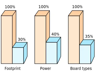
The AXE hardware evolution programme has successfully reduced the size of hardware by between 70% and 90%; cabling in the exchange has been reduced by 90%, and power has been reduced by 75%. Therefore, operators can expect that the time and
re-sources needed for installing the hardware will also decrease by between 70% and 90%. The delivery of fully equipped and tested ex-changes will further simplify installation.
The following aspects contribute towards reducing operator costs for running the new exchanges:
• smaller footprints require less floor space (reduced overhead);
• costs of power (batteries, rectifiers and kW) and cooling are reduced (reduced overhead);
• fewer spare parts are needed (smaller facilities, smaller stores);
• operations have been simplified (less staff, less training);
• less hardware implies that the mean time between failures (MTBF) increases, while the repair time decreases – in that way, the total down time, due to hardware fail-ures, will decrease;
• pooled devices;
• programmable platforms.
The hardware evolution described in this ar-ticle represents only a first step in Ericsson’s AXE hardware evolution programme. In subsequent phases of the programme, AXE will be migrated towards an open hardware architecture that supports datacom func-tionality, asynchronous transfer mode (ATM) switching, high-speed interfaces and multiprocessor configurations.
References
1 Hägg, U., Persson, K.: New hardware in AXE 10. Ericsson Review
63(1986):2, pp 86-92. 2 Stockman, B. and Wallers, A.:
BYB 501 metric equipment practice. Ericsson Review 74(97):2, pp. 62-67. 3 Hansson, U., Paone, T.: The group
switch subsystem – an enhanced com-petitive group switch. Ericsson Review 74(1997):2, pp 68-73.
4 Eriksson, A., Eriksson, G., Karlsen, J., Roxström, A., Vallon Hulth, T.: Ericsson echo cancellors – a key to improved speech quality. Ericsson Review 73(1996):1, pp 25-33.
100% 100% 100%
30%
40%
35%
Footprint Power Board types Average exchange reduction
Figure 13