STRESS CONCENTRATION DURING PELLET CLADDING
INTERACTION: COMPARISON OF CLOSED-FORM SOLUTIONS WITH
2D(R,
θθθθ
) FINITE ELEMENT SIMULATIONS
J. Sercombe1, R. Masson2, T. Helfer1
1
CEA DEN, F-13108 Saint-Paul-Lez-Durance, France
2
CEA DEN, F-13108 Saint-Paul-Lez-Durance, France, formerly EDF R&D, Les Renardières, 77250 Moret sur Loing, France
E-mail of corresponding author: [email protected]
ABSTRACT
This paper presents closed-form solutions to estimate the pellet crack opening and the clad stress distribution in front of an opening pellet crack during in-reactor normal and off-normal operating conditions. The analytical solutions are compared to 2D finite element simulations results obtained from the fuel code ALCYONE with a very refined mesh. The calculated radial crack opening profiles during base irradiation and power ramp show a good agreement with ALCYONE results even if strong pellet-cladding interaction is present. The stress distribution in the cladding resulting from an opening pellet crack is correctly estimated from the proposed modified version of Roberts’ model with the assumption of a linear angular variation of the pellet-clad contact pressure and a constant prescribed radial displacement.
INTRODUCTION
Failure of zirconium alloys fuel rods by Pellet Cladding Interaction (PCI) has been studied worldwide for many years [1] but remains a matter of concern since no absolute remedy has yet been found. On a mechanical standpoint, the main parameters that govern PCI failures are however well known: pellet “hourglassing” or “wheatsheaf” due to the high radial thermal gradient in the pellet which leads to over-straining of the cladding in front of pellet ends, pellet radial cracking which induces strain-stress concentration in the cladding [2] and friction at the pellet-cladding interface which maximize interfacial shear and circumferential stresses in the cladding [3]. Fuel performance codes are generally based on a radial one-dimensional description of the fuel pellet and the cladding and hence cannot provide estimates of stress or strain concentration in front of an opening pellet crack which is by essence a two-dimensional problem. Some authors have derived closed-form solutions which give the stress concentration factor in function of the applied thermal and mechanical loadings on the pellet and the cladding [2][3][4]. These models are then used in fuel performance codes to improve the one-dimensional description of PCI [5][6]. A pre-requisite to the use of stress concentration models is that the crack opening at the crack tip is known. In this respect, so-called “hoop enrichment models” have recently been developed to trigger the impact of the thermal gradient, of solid swelling and of the contact pressure in a pellet fragment on the crack opening [6].
Nowadays, progress in computational performance and finite element codes has made possible the simulation of the thermo-mechanical behavior of a fragmented pellet enclosed in the cladding. Two- or three-dimensional simulations of this problem are thus proposed in the fuel code ALCYONE [7] where the angular (and axial) distribution of the pellet-clad interfacial contact pressure and shear stresses can be estimated at any time of a power transient. Provided the mesh refinement is sufficient, the stress and strain concentration in the cladding in front of the pellet crack can be described, particularly in two-dimensional calculations [8]. The complexity of the problem is due to the high level of interaction between adjacent pellet fragments (with partial crack closure along the pellet radius) and at the pellet – clad interface (unilateral contact and friction). In practice, it is important to assess the validity of the stress and strain states in the cladding resulting from PCI as estimated by the finite element method. In this respect, closed-form solutions can be useful.
In this paper, closed-form solutions for the crack opening and the stress intensification in the cladding in front of the crack tip are proposed and compared to 2D simulations of PCI performed with ALCYONE.
PELLET FRAGMENT MODEL Muskhelishvili’s formulation
considering plane stress conditions, the two components of the displacement field, denoted by ux
( )
x,y and uy( )
x,y in cartesian coordinates, can be expressed as a function of two potentials(
Ω( ) ( )
z ,wz)
of the complex variabley i x
z= + as (see reference [9]):
( )
{
(
) ( )
z z( ) ( )
z wz}
Gz D u i
ux+ y= = 3−4ν Ω − Ω′ − 2
1
where z denotes the conjugate of the complex number z
.
If this body is submitted to an isotropic stress free strainfield εan( zz), additional terms appear in the former expression:
(
) ( )
( ) ( )
[
]
( )
− + + − Ω′ − Ω −
=
∫
zz andt t t z
z w z z z G
z D
0
2 1 1 1 2 1 4
3 2
1 )
( ε
ν ν
ν (1)
The strain and stress fields can be derived from the displacement field by elementary algebraic manipulations. If the derivatives of the two complex potential are holomorphic functions of the complex variable, the stress field satisfies the equilibrium equations.
Application to a pellet fragment with isotropic swelling
The pellet is divided in N identical fragments (see Figure 1). The contact pressure Pcont is assumed to be uniformly applied on the periphery of each pellet fragment while the swelling radial distribution applied to the pellet is isotropic and approximated by:
( )
∑
≥
= 1
k
k an k an
r
r ε
ε . In this general expression, the thermal strain gradient
corresponds to k=2.
Fig.1: pellet fragment submitted to the pellet-cladding contact pressure with two zones delimited by the contact radiusR c
The pellet fragments are submitted to contradictory effects: the thermal strain gradient tends to open the radial cracks while the contact pressure has an opposite effect. The balance between these two phenomena is represented by a contact radius (denoted as R on Figure 1). To derive relevant approximations of the displacement field, the c
pellet fragment is modeled as two zones (see Figure 1). In the first zone (0≤r≤Rc), pellet fragments are in contact and the displacement field is given by (axisymmetric solution with Ω
( )
z =γ z,w( )
z =0):(
)
∑
≥
= +
− + +
− =
1
0 ,
1 1
1 2
1
k
k an
k
r u
k r r
G
u θ
ν ν ε ν
γ
In the second zone (Rc ≤r≤R), the two complex potentials are chosen as follows:
( )
∑
( )
∑
≥
≥
− =
+ =
Ω
1 0
0 1
ln ,
ln
k
k an k k k
k an k k
r z A z z
w r
z A z
z α ε β ε (2)
(
)
(
( )
)
(
( )
)
[
]
(
)
( ) (
) ( )
( )
− − + − + + − − − − =∑
≥ θ θ ν θ θ ν θ β θ α ν ε θ sin ln sin 4 4 cos 4 2 2 1 sin 1 sin 4 3 2 1 0 1 r r G A r k k k G u k k k k an k (3)the unknown constants
(
γ,r0,αk,βk)
being calculated with respect to the following boundary conditions:( ) ( )
− = +c rr c
rr R σ R
σ , uθ(Rc)=0 and σθθ
(
r,θm)
=σrθ(
r,θm)
=0for Rc≤r≤R. Finally, the constant A is such that the average radial stress on the pellet periphery is equal to the contact pressure while the radius contact (Rc) ensures the continuity of the radial displacement between the two zones.STRESS CONCENTRATION OVER AN OPENING PELLET CRACK
Roberts’ solution
In its paper, Roberts studied the case of a pellet divided by N regularly spaced cracks having an angular displacement of 2θm between each one and a crack width of 2φ [3], as represented in Figure 2. The crack width can
be computed from the pellet displacement field (equation (3)) by the following relation:
(
R m)
uR θ
φ 2 θ ,
2 = (4)
Fig.2: Schematic fuel – clad model used in the calculations.
The external pressure was assumed equal to zero. A uniform normal pressure on the inner cladding surface was assumed to act together with a shear stress which depends on the normal pressure and frictional coefficient. Thus, the problem resolved into a standard one, namely finding the distribution of elastic stresses in a thick-walled cylinder having specified normal and shear stresses on the inner and outer surfaces. Robert showed that an Airy stress function of the following form could satisfy the compatibility equation and the symmetries of the problem:
) cos( ) ( ln 2 2 2 0 2 0
∑
∞ = + − − + + + + + + = Φ m m m m m m m mmr B r C r D r m
A r
B r
A θ (5)
with A0, B0, Am, Bm, Cm and Dm constant parameters. For the proposed stress function, the plane strain stresses are :
The displacements are obtained according to the following relations :
[
]
[
]
− + + + + − + = − − + − + − − + − − =∑
∑
∞ = + − − − − + ∞ = + − − − − + 2 1 1 1 1 2 1 1 1 1 0 0 ) sin( )) 1 ( 4 ( )) 1 ( 4 ( 2 1 ) cos( ) ) 2 1 ( 2 ( ) ) 2 1 ( 2 ( ) 2 1 ( 2 2 1 m m m m m m m m m m m m m m m m m m r m r D m r mC r mB r A m G u m r D m r mC r mB r A m r B r A G u θ ν ν θ ν ν ν θ (7) In the above expressions, σrr denotes the radial, σθθ the hoop and σrθ the shear stress. The radial and circumferential displacements are signified by urand uθ, respectively.Closed-form solution for a prescribed constant radial displacement
In this work, the original formulation proposed by Roberts has been improved to account for boundary conditions closer to those taking place in a PWR fuel rod: first, the external pressure of the coolantpext is assumed non zero, second, the fuel rod gas pressure pgasis applied on the part of the inner clad surface which is not in contact with the pellet (−φ≤θ≤φ), third, a linear evolution of the contact pressure with angular position
2
1 K
K
pcont = θ+ is assumed.
The constants A0 and B0 relate to the uniform stressing of a thickwalled elastic cylinder and may be
obtained directly from the boundary conditions σrr = pext on r=a, the outer surface, and σrr =pcontmean on r=b, the inner surface. pcontmean is the average contact pressure applied on the inner surface.
In the original formulation of Roberts, the remaining coefficients follow from Fourier expansions of the boundary conditions on the inner and outer surfaces of the cladding, and the requirement that these are equal to the stresses (6) at the appropriate surfaces. In the present case, the boundary conditions are :
≤ ≤ − − = = = ≤ ≤ = = = ≤ ≤ − = = = = = = = = φ θ θ µσ σ θ σ θ θ φ µσ σ θ σ φ θ φ σ σ σ σ θ θ θ θ m rr r cont rr m rr r cont rr r gas rr r ext rr pour and p b r pour and p b r pour b r and p b r a r and p a r ) ( ) ( ) ( ) ( 0 ) ( ) ( 0 ) ( ) (
with µ the pellet-clad friction coefficient. Expressing the variation of stress on the inner surface of the cladding as Fourier sums gives :
(
cos( ) ( 1))
sin( ) sin( )) ) 1 ( ) (cos( 2 ) ( 1 2 1 1
2 φ θ
π π φ φ π π φ µ
σ θ iN iN
N i K iN N N i K i iN K b i i i r
∑
≥ − − − + − − =(
sin( ) (( 1) cos( ))
cos( )2 ) sin( ) ( 2 ) ( 1 2 1 2 θ φ φ φ π π φ
σ iN iN iN iN
N i K i iN K p p b i i gas mean cont rr
∑
≥ − − − − − + =Comparison of these expressions with stresses (6) shows that m will be summed multiples of N, e.g., m=iN. For each summation index m, the boundary conditions lead a system of four equations that are sufficient to determine the constants Am, Bm, Cm and Dm. In the case of the linear evolution of the contact pressure with θconsidered here,
2
1 K
K
pcont = θ+ , the parameters Am, Bm, Cm and Dm can be expressed as linear functions of K . In turn, the radial 1
angular variation of the radial displacement (7) is enforced by the following condition on the contact pressure slope
1 K :
[
]
−
∫
θ θ θθ φ
d u
u
m
m r r K
2
) ( ) ( min
1
COMPARISON OF CLOSED-FORM SOLUTIONS WITH ALCYONE 2D SIMULATIONS
Short description of ALCYONE 2D(r,θθθθ) scheme
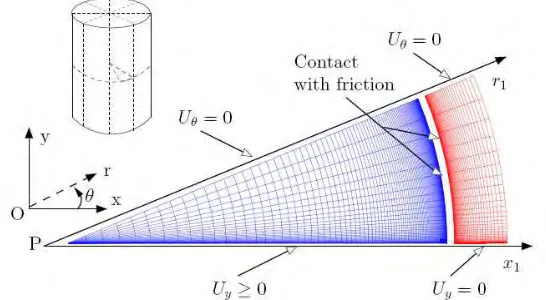
ALCYONE is a multi-dimensional fuel performance code [7] which allows one to model the in-reactor behavior of a complete fuel rod (standard 1D1/2 fuel performance code), of a pellet fragment (3D) or of the mid-pellet plane of a mid-pellet fragment (2D generalized plane strain). The different schemes use the same Finite Element (FE) code CAST3M [9] to solve at each time step the thermo-mechanical equilibrium of the pellet-gap-cladding system. The 2D configuration can be used to assess precisely stress concentration in the cladding near a pellet crack tip provided the mesh size is smaller than the crack opening [8]. The mesh and boundary conditions are described in Figure 3. The minimum mesh size is close to 1 micron.
Fig.3: Mesh and boundary conditions in ALCYONE 2D simulations.
The boundary conditions account for the geometrical symmetries of the problem and for the pellet-cladding and pellet-pellet interactions. Pellet-pellet inter-penetration along the fracture plane (Px1) is forbidden by the
unilateral contact condition Uy≥0. Concerning loading conditions, the gas pressure is applied to the cladding inner surface and to the pellet fragment outer surface when the gap is open. The external pressure is applied to the cladding outer surface. At the pellet-cladding interface, unilateral contact is assessed and a Coulomb model is introduced to simulate friction-slip or adherence. To be consistent with the closed-form solutions presented in this paper, linear elastic behavior is assumed in the reference case for both the pellet and cladding materials. Only thermal swelling is considered in the calculations. The thermal conductivity of the pellet material and elastic properties (shear modulus, Poisson’s ratio) are however temperature and porosity dependent.
Case study
0 50 100 150 200 250 300
0 2000 4000 6000 8000 10000 12000 14000
Time (hours)
L
in
e
a
r
h
e
a
t r
a
te
(
W
/c
m
)
1
2
0 50 100 150 200 250 300 350 400 450 500
0 5 10 15 20 25 30
Time (hours)
L
in
e
a
r
h
e
a
t
ra
te
(
W
/c
m
)
3 4
Fig.4: Irradiation history during normal (base irradiation, left) and off-normal (power ramp, right) operating conditions.
To apply the closed-form solution for the crack opening, some input data are necessary: the Poisson’s ratio and shear modulus, the radial thermal strain distribution, the outer pellet radius and the contact pressure. At each time step of interest, these input data are obtained from the 2D ALCYONE simulations by averaging their variations in the angular direction. The calculated tip crack opening (equation (4)) is then used to estimate with the modified Robert’s model the stress and strain distribution in the cladding. The friction coefficient considered here equals 0.47 and is consistent with measures on non-irradiated materials [10].
Results concerning the opening of the pellet crack
The opening of the pellet crack along the pellet radius estimated at different times according to expression (3) are compared in Figure 5 to the finite element based calculated values from ALCYONE 2D. To be consistent with the boundary conditions on the pellet external surface considered in the closed-form solution (no shear stresses), friction has not been activated in the ALCYONE 2D simulation.
0 1 2 3 4 5 6 7 8
0 1 2 3 4 5
Pellet radius (mm)
C
ra
ck
o
p
e
n
in
g
(
µ
m
)
Analytical Alcyone 2D
Point 1
0 1 2 3 4 5 6 7 8 9 10
0 1 2 3 4 5
Pellet radius (mm)
C
ra
c
k
o
p
e
n
in
g
(
µ
m
)
Analytical Alcyone 2D
Point 2
0 5 10 15 20 25
0 1 2 3 4 5
Pellet radius (mm)
C
ra
ck
o
p
e
n
in
g
(
µ
m
)
Analytical Alcyone 2D
Point 3
0 5 10 15 20 25
0 1 2 3 4 5
Pellet radius (mm)
C
ra
c
k
o
p
e
n
in
g
(
µ
m
)
Analytical Alcyone 2D
Point 4
Figure 5 shows that the closed-form solution compare relatively well with the finite element solution. In particular, the near-tip crack opening is well reproduced when pellet-clad contact is not effective or weak (point 1 and 2). This is less true when strong pellet-clad contact occurs (point 3 and 4) due to the strong angular variation of the contact pressure (see Figure 6 below where the contact pressure is markedly peaked in front of the crack) which is not taken into account in the analytical model (the solution is obtained for a constant average pressure). This leads to an overestimation of the near-tip crack opening by about 25%. The closed-form solution predicts a r3 dependency for the crack opening. Prior to pellet clad contact (point 1), this shape is in fact obtained in the ALCYONE 2D finite element simulation. The r3 shape is however clearly lost when strong contact occurs which might again be a consequence of the contact pressure intensification near the crack tip. The contact radius (maximum radius at which the crack is closed) is generally underestimated by the closed-form solution whatever the time considered. This result is due to the approximation of the pellet fragment with a two-zones model where stress continuity at the interface is only ensured on average. In the case of point 1, a better agreement can be obtained if the fuel rod gas pressure is used in the analytical solution instead of the zero-contact pressure.
Results concerning the stress concentration in the cladding
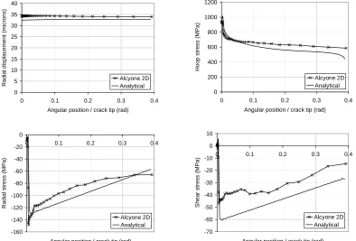
The ALCYONE 2D simulation is now performed with friction since shear stresses are included in the derivation of the closed-form solution for the stress concentration problem. The two main assumptions behind the analytical solution are first that the angular variation of the contact pressure is linear and second that the radial displacement of the inner clad surface is almost constant. As illustrated in Figure 6, results obtained with ALCYONE 2D at point 3 confirm the constancy of the radial displacement and the close to linear shape of the radial stresses except in the vicinity of the crack tip.
0 5 10 15 20 25 30 35 40
0 0.1 0.2 0.3 0.4
Angular position / crack tip (rad)
R
a
d
ia
l
d
is
p
la
c
e
m
e
n
t
(m
ic
ro
n
s
)
Alcyone 2D Analytical
0 200 400 600 800 1000 1200
0 0.1 0.2 0.3 0.4
Angular position / crack tip (rad)
H
o
o
p
s
tr
e
s
s
(
M
P
a
)
Alcyone 2D Analytical
-160 -140 -120 -100 -80 -60 -40 -20 0
0 0.1 0.2 0.3 0.4
Angular position / crack tip (rad)
R
a
d
ia
l
s
tr
e
s
s
(
M
P
a
)
Alcyone 2D Analytical
-70 -60 -50 -40 -30 -20 -10 0 10
0 0.1 0.2 0.3 0.4
Angular position / crack tip (rad)
S
h
e
a
r
s
tr
e
s
s
(
M
P
a
)
Alcyone 2D Analytical
Fig.6: Radial displacement (top left), hoop (top right), radial (bottom left) and shear stress (bottom right) profiles on the inner clad wall according to the analytical solution and the ALCYONE 2D simulation (results at point 3).
the assumption that sliding occurs everywhere at the pellet fragment – clad interface. ALCYONE 2D simulations results show on the contrary that sliding at the pellet-clad interface might not be effective everywhere, in particular in the near-tip region.
CONCLUSION
In this paper, closed-formed solutions concerning PCI have been proposed and compared to 2D finite elements simulations performed with the fuel code ALCYONE. The first solution gives the evolution of crack opening in a pellet fragment subjected to a thermal gradient. The second solution describes the stress state in a cylindrical cladding loaded by a pellet fragment and catches the stress concentration in front of the pellet crack tip. Analytical results were found in good agreement with finite element results at all times during base irradiation or power ramp irradiation histories. These models are of interest for the validation of multi-dimensional fuel codes and for the enrichment of standard fuel performance codes which are usually based on a one-dimensional description of PCI. With the proposed approach, three-dimensional based PCI failure criteria such as those proposed in [8] could then be used in post-processing of standard one-dimensional calculations. Further work will be dedicated to the extension of these models to pellet and clad non-linear material behavior (creep, plasticity, …).
ACKNOWLEDGEMENTS
The authors would like to thank the students that worked successively on the subject for their master thesis, namely Sébastien Muller, Mathieu Turban, Ludovic Giusti, Julien Graffard and Jean-Marc Bot. The authors acknowledge EDF and AREVA for their financial support to this research.
REFERENCES
[1] Cox B., “Pellet-Clad Interaction (PCI) failures of zirconium alloy fuel cladding – a review”, Journal of
Nuclear Materials, Vol. 172, 1990, pp. 249-292.
[2] Gittus J.H., “Theoretical analysis of the strains produced in nuclear fuel cladding tubes by the expansion of cracked cylindrical fuel pellets”, Nuclear Engineering and Design, Vol. 18, 1972, pp. 69-82.
[3] Roberts G., “The concentration of stress in cladding produced by the expansion of cracked fuel pellets”,
Nuclear Engineering and Design, Vol. 47, 1978, pp. 257-266.
[4] Retel V., Trivaudey F., Boubakar M.L., Perreux D., Thevenin Ph., “Comparative effects of structural and material parameters variability on Pellet-Cladding Interaction in a PWR fuel rod”, Nuclear Engineering
and Design, Vol. 228, 2004, pp. 35-46.
[5] Yaung J.Y., Okrent D., Wazzan A.R., “A simple computer model of pellet/cladding interaction including stress corrosion cracking”, Nuclear Technology, Vol. 71, 1985, pp. 644-650.
[6] Baron D., Thevenin P., Largenton R., Masson R. « CYRANO3 the EDF fuel code performance especially designed for engineering applications. In 2008 Water Reactor Fuel Performance Meeting (Corée). Longman, Harlow, 2008, Paper 8032.
[7] Sercombe J., Michel B., Thouvenin G., Petitprez B., Chatelet R., Leboulch D., Nonon C., “Multi-dimensional modeling of PCMI during base irradiation and ramp testing with ALCYONE V1.1”,
International Conference TopFuel 2009, Paris, France, September 6-10, 2009.
[8] Michel B., Sercombe J., Thouvenin G., “A new phenomenological criterion for Pellet Cladding Interaction rupture”, Nuclear Engineering And Design, Vol. 238, 2008, pp. 1612-1628.
[9] Muskhelishvili N.I. « Some basic problems of the mathematical theory of elasticity », 4ème edition, P. Noordhoff, Groningen-The Netherlands (1963).
[10] CAST3M, http://www-cast3m.cea.fr/cast3m/index.jsp.