Seismic evaluation of c o n t a i n m e n t shell - W W E R - 1 0 0 0 type reactor building
M.Kostov ~), D.Stefanov ~), N.Koleva
1)
N.Krutzik 2)1) Bulgarian Academy of Sciences, Central Laboratory for Seismic Mechanics and Earthquake Engineering 2) Siemens Nuclear Power GmBH (Framatom ANP), Offenbach am .Main
ABSTRACT
This investigation is part of the Modernization Program for units 5/6 (VVER 1000) of Kozloduy NPP, Bulgaria. The Reactor Building is studied for the recently defined Review Level Earthquake (RLE) and Local Earthquakes (LE). A 3-D Finite Element model is used for definition of seismic response and seismic capacity assessment. Most attention is paid to the containment evaluation. For that purpose a complementary finite element model is developed. It represents the cylinder shell, the dome and the supporting ring structure of the containment. The model is characterized by refined mesh and detailed representation of loading caused by the stressing tendons. The structural stiffness increase due to prestressing is considered in the modal analysis. First static analysis is performed with the pre-stressing loads, consequently eigenvalue analysis is done under consideration of the strains due to prestressing.
The capacity check of the containment is performed in meridian and circumferential direction separately. Principle stresses from several load combinations are examined in order to determine the scenarios for containment cracking and loss of integrity. The domination loading is that caused by LOCA. The tension stresses however do not affect the structural integrity. The seismic effects are of minor importance. The HCLPF values of several scenarios studied show very high acceleration that may cause failure.
INTRODUCTION
The seismic reevaluation is performed for the new RLE defined for the site of Kozloduy NPP. The original design is based on PGA 0. l g. The reevaluation is performed for twice as big acceleration and very broad band acceleration response spectrum (the flat part of the acceleration response spectra for 5% damping with the frequency interval 0.6 to 10 Hz is 0.46g). In addition to the RLE also seismic excitation form local sources are taken into account, that are characterized by intensive vertical shaking. Details of the seismic excitation are presented in [1].
For critical structures as nuclear power plants the seismic safety assessment could be performed using deterministic and/or probabilistic methods of investigation. Both methods are followed in the seismic evaluation of the containment shell under investigation.
The reactor building is seismic category I structure. The seismic reevaluation the containment is analyzed for seismic excitations that are enveloping RLE and LE excitation. The acceleration time history used in the analysis corresponds to enveloped and broadened response spectra of those excitations.
GENERAL DESCRIPTION OF THE BUILDING STRUCTURE
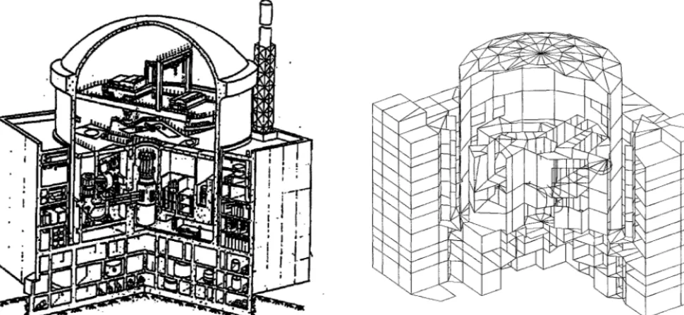
The reactor building unit 5/6 NPP Kozloduy is a complicated space structure which consists of four main parts - foundation block, containment shell, surrounding building and internal structure- fig. 1. The joining element of all of them is the massive RC plate with thickness 2.40 m at level +13.20.
The foundation block consists of 2.80 m thick foundation plate at level -7.00 and two intermediate 0.60 m thick plates at levels 0.00 and 6.60. The base structure is adequately stiffened by several walls.
The containment shell is reinforced prestressed concrete structure which consists of two p a r t s - cylinder and dome. The wall thickness is 1.2 m for the cylinder and 1.10 m for the dome. Inside of the wall there is a steel liner which acts as a leakage barrier. The cables are anchored in a stiff ring girder at the junction of the cylinder with the dome. There is a crane path for polar crane at level +46.80.
The surrounding building with dimensions 66.0 / 66.0 m is located above level +13.20 around the containment shell. There are rooms with relatively light equipment.
The internal structure is located inside the shell above level +13.20 and supports the reactor and primary circuit. GLOBAL FINITE ELEMENT MODEL
A global finite element model is used for investigation of the seismic response of the whole building structure. This model describes all main parts of the reactor building and takes into account the soil-structure interaction. The model of the foundation block consists of 801 nodes and 1430 elements. The dome and the cylinder are modeled with shell elements and
SMiRT 16, Washington DC, August 2001 Paper # 1060
the supporting ring with beam elements. The total number of the nodes and elements of the containment shell is 129 and 213 respectively. The surrounding building is modeled with 687 nodes and 1280 elements. The internal structure is described with 217 nodes and 321 elements. It includes the reactor cavity, the fuel pools, the reinforced walls and plates in the hermetic zone. A cross section of the model is shown in fig.2.
\
i
I J "
!1
i ! i i
Fig. 1 Reactor Building structure- 1000 MW type fig.2 General view of the complex 3-D model
The soil structure interaction is accounted by introducing spring-dashpot system on the basemat contact surface. The spring-dashpot characteristics are determined after detailed impedance analysis that is not presented here. Generally the soil- structure interaction is dominating the seismic response of the complex structure because the underlying soil layers have relatively small dynamic stiffness. Details on the dynamic analysis of the complex model are presented elsewhere [2, 3].
MODELING OF CONTAINMENT PRESTRESSING
It is very important to model the prestressing of the containment because the real stiffness of the structure should be taken into account in the eigenvalue analysis. The prestressing modeling is based the concept of replacing the prestressing elements by the equivalent loading caused by them in the structure.
Modeling of the dome prestressing
The total number of tendons in the dom is 32. They create an orthogonal mesh and the distance between them is 0.90m in the central area. The equivalent loading is determined in the following way: If N = 10000 kN is the prestressing force in one tendon than the respective line loading is q = N / R = 285.7 kN/m where R is the dom radius. Because the tendons are two orthogonal sets for the central part of the dome their action can be represented as distributed load with an intensity p = 634.9
kN/rn
The dome area can be divided into three zones: central zone where two tendon sets acts, four end zones where only one tendon set acts and four zones where there is no prestressing. The distribution of the above mentioned loading on the dome is done as follows:
* In the central zone is assumed full loading, i.e. p = 634.9 kN/m 2.
. In the end zones is assumed 50% of the fitll loading, i.e. 0.5 * p = 317.4 kN/m 2.
Modeling of the cylinder prestressing
The total number of tendons in the cylinder is 96. The equivalent loading on the cylinder wall consists of two parts - horizontal component acting in circumferential direction and vertical component. The horizontal component is determined in the same way as that of the dome, i.e:
P1 = 96*n*cos~x/(R*H) - 686 kN/m 2 where: N is the prestressing force in one tendon;
R is the radius of the cylinder; H is the height of the cylinder.
The vertical component is modeled as concentrated load at the supporting ring nodes: P = 96*2*N*sinot/16 = 68750 kN
The global model of the building structure enables the evaluation of the global structure seismic response but the containment mesh size is not suitable for detailed static investigations. That's why it is necessary to develop a detailed containment model for comprehensive analysis. The seismic loading of the sub-model (containment) is determined by analysis of the global model.
CONTAINMENT MODEL
In order to perform detailed investigation of the containment shell a new finite element model is developed. This model describes the cylinder, the dome and the supporting ring structure. The model is fixed at the slab at level +13.20. It is characterized by very refined mesh. The model consists of 1952 shell elements and 60 beam elements for the ring at the junction of the cylinder and the dome. The total degree of freedom is 11640. The general view of the model is shown in fig.3.
fig.3 General view of the shell model
The seismic load for the model is determined by the following steps: • calculation of acceleration time histories ( three components) for
nodes which are common for containment cylinder and slab at level +13.20 using the global model of Reactor Building;
• calculation of acceleration response spectra for selected nodes; • calculation of envelope of all spectra;
• broadening of final spectrum;
• generation of new time histories (three components) for this level using the above spectrum.
This procedure has the advantage of providing enough conservatism taking into account the global response of the whole building structure. DYNAMIC CHARACTERISTICS
in two steps. First static analysis of the system subjected to the equivalent prestressing load is performed. A geometric stiffness matrix is formed based on the obtained displacements. It reflects the geometrical parameters of the system (deformed geometry due to the prestressing) [5,6]. The second analysis is eigenvalue determination. A stiffness matrix obtained as a sum fi'om the elastic stiffness matrix (describing original system) and geometric stiffness matrix (describing deformed system) is used [5,6].
In Table 1 are given the values of the first five eigen frequencies with and without taking into account the prestressing of the structure. The considerable difference in the values shows that the prestressing changes considerably the stiffness of the structure and therefore should be taken into account in the seismic analysis.
Tablel. Natural frequencies
Number
Frequencies Hz
Without pres~essing Wilh prestressing
1 4.595 25.280
2 4.595 25.349
3 6.801 35.126
4 6.829 35.292
5 7.385 41.214
CAPACITY ASSESSMENT OF THE CONTAINMENT STRUCTURE
1. P L + P + R L E
2. PL + P + LOCA + (1/2 RLE)
where: PL is permanent loads, including dead load and crane load; P is prestressing loads;
LOCA is loss-of-coolant accident pressure load; RLE is the review level earthquake.
Capacity assessment of the elements of the containment is done according to [7]. The shell is made from concrete M400 (C35) with following properties:
fc'=25.5 M P a - specified compressive strength of concrete; f~_2.75 MPa- specified tensile strength of concrete.
The reinforcement bars are from steel A-Ill with specified yield strength fyt=410 MPa.
The capacity check is done for load combinations Nol and No2 in meridian and circumferential direction separately. The two directions correspond to local coordinate axes "y" and "x" for the finite elements.
Parts of the results from the capacity check of containment cylinder part for load combination 2 are given in Table 2, the units are [MN, MN.m]. In this table the following notation is used:
Fy is normal force in meridian direction; Fx is normal force in circumferential direction;
Mx is external flexural moment in circumferential direction; My is external flexural moment in meridian direction;
Mnx is design flexural moment (resistance) in circumferential direction; Mny is design flexural moment (resistance) in meridian direction.
Table 2 Results for the cylindrical shell
ELEM. Fx
-4.303 -4.278 -4.258 -4.241 -4.229 -4.220 -4.214 Fy -7.620 -7.498 -7.403 -7.332 -7.280 -7.245 -7.223 Mx .418 .420 .421 .423 .424 .424 .425 ]VInx 2.772 2.764 2.757 2.752 2.748 2.745 2.743 CHECK O.K O.K O.K O.K O.K O.K O.K My 2.091 2.100 2.108 2.113 2.116 2.120 2.122
8 -4.211 -7.212 .425 2.743 O.K 2.124
9 -4.211 -7.211 .425 2.742 O.K 2.125
.425 -7.222
10 -4.213 2.743 O.K 2.125
Mny CHECK
3.483 O.K. 3.473 O.K. 3.465 O.K. 3.459 O.K. 3.454 O.K. 3.450 O.K. 3.448 O.K. 3.447 O.K. 3.447 O.K. 3.448 O.K.
Stresses results from load combination (PL + P + LOCA) are presented hereafter. The top major stresses for containment dome are plotted in rigA.
3311.
905 2
103 3 -698 6 -2302. -3104. -3906. -4708 1310 m i .584 :; ? ~i?!i: -1216, 1847 -2479 -3110 -3742. -4373
The maximum tensile value of top major stresses is 3.31 MPa. The top minor stresses for the dome are given in fig.5. The maximum tensile value is 1.31 MPa. All bottom stresses of the dome are compressive. The comparison of these maximum tensile stresses with the specified tensile strength of concrete (f¢~__2.75 MPa) shows that there will be some cracks on the top side of the dome. In spite of this the concrete cracks are not expected to pass trough the entire wall thickness, furthermore the tightness function provided by the steel liner is not affected.
The top major stresses for containment cylinder are plotted in fig.6. The maximum tensile value of top major stresses is 1.91 MPa. The top minor stresses for containment cylinder are compressive - fig.7. All bottom stresses for cylinder are compressive too. The results received show that cracks are not expected to appear at the containment cylinder.
L:
Fig.6 Cylinder, Top major stresses [MPA.E-3]
1918. -934.3
!:-4L:, I ~ I~'.,:!~: I
:3t8
-215 3
-748.6
-1282.
-1815.
-2849.
-2882.
-3415.
Fig.7 Cylinder, Top minor stresses [MPA.E-3]
!iU~!i -181~
-2113.
-2407
-2702
-2997.
-3291.
-3588.
-388t.
The capacity assessment of the supporting ring is done for the most stressed area. The compressive normal force is P=61.2 MN and bending moment M = 12.8 MN.m (load combination 2). The design bending moment (resistance) according to [5] is equal to Mn=38.4 MN.m, i.e. the bearing capacity of the ring is sufficient.
FRAGILITY ANALYSIS
The results show that the main contributors to the final stresses are the loads due to LOCA. The influence of the seismic excitation on the structural safety is very small. The results are confirmed from the probabilistic analysis. Several scenarios for containment failure are considered in a fragility analysis. The fi'agility curves are developed according to the methodology described in [8]. Hereafter the fragility parameters are presented only for 3 scenarios. The first one is shear failure of containment at level 13.20. The second scenario is tension failure due to bending of containment at level 13.20. The third one is impact between auxiliary building and containment at level 45.60. The last scenario is relatively rear because containment structures are usually stand alone structure. The VVER1000 layout is different, i.e containment structure is surrounded by an auxiliary structure. The third scenario is examining the possibility of impact between the containment and the surrounding auxiliary structure. The characteristic values of the fragility curves are presented in table 3. The respective fragility curves for these scenarios are plotted in figures 8, 9 and 10.
1 . o 1 . 0 .
I I I
i
. .
o..Lo
/ / / -
-
t ' * ' * ' ' ~ ' ' ' ' " ' I L O 4 . 0 ILO - - lO,.O . . . . ltLO 1 4 . 0 10.0
~-uilttv P,ursmet~r (PG& E} ha~li(~y P ~ t ~ r (PG& z)
_ .
7- ?
0°6 " ~I ,~ ~ I " ~ '
~
0 , 3 ~ oe
, c ~ . , 8 ~ . . . . j . . . . .
~,~ ... i~a' ... L, w .o o.o
fig.10 Fragility curves - Impact between auxiliary building and containment at level 45.60
Table 3. Fragility parameters of Unit 5, Kozloduy NPP containment
Scenario Shear faihre at the lxtse, level + 13 20m
Tension banding faihare at the lxtse, level +13.20m
Impact baween auxiliary .building and containment, level +45.60m
Av
4.50 8.14 2.49
HCLPF 3.01 5.39
1.46
u r u m 0.06 0.18 0.1 0.15 0.1 0.225
CONCLUSION
The seismic analyses carried out for containment shell leads to the following main conclusions"
1. The results show that the procedure used for definition of the seismic excitation at the base of the complementary shell model is conservative. It takes into account the global response of the building structure.
2. The prestressing influenced considerably the dynamic characteristics of the structure. The comparison of natural frequencies show that due to prestressing the stiffness increases significantly.
3. The procedure for substituting the tendons by equivalent loading is simple and effective for application. It should be however applied on dense meshed models in order to reflect the variation of the prestressing force.
4. Based on the comparison between the maximum tensile principle stresses and the specified tensile strength of concrete the conclusion is drown that local concrete cracks are possible to appear only on the top surface of the containment dome. The general conclusion is that the containment shell structure of unit 5/6 - NPP Kozloduy has sufficient bearing capacity.
REFERENCE
1. Varbanov G.,Kostov M.,Kaneva A.,Krutzik N., Seismic Upgrading of the Turbine Hall and Electric Building of Unit 5/6 Kozloduy NPP, SMIRT 16, Division M, Washington, 2001.
2. Kostov M., et al., Probabilistic Response and Capacity Evaluation of VVER 1000 Reactor Building, KOlzoduy NPP, X ECEE, Vienna, 1994.
3. Kostov M., et al, Probabilistic SSI Analysis of Unit 5/6, Kozloduy NPP, Proceedings of SMiRT 13 Conference, Porto Alegre, 1995.
4. STARDYNE, Structural Analysis System, TITAN Corporation. 5. Clough W.,J.Penzien, Dynamics o f Structures, New York, 1975.
6. Cook R., Concepts and Applications o f Finite Element Analysis, John Wiley & Sons, New York, 1989. 7. Code Requirements for Nuclear Safety Related Concrete Structures (AC1349-85)
![Fig.4 Containment dome, Top major stresses [MPA.E-3]](https://thumb-us.123doks.com/thumbv2/123dok_us/1692585.1214090/4.596.39.524.18.665/fig-containment-dome-top-major-stresses-mpa-e.webp)

