Progress of the 2000 Addenda of the RSE-M Code in Analytical Evaluation
and Acceptance Criteria of Flaws
Bruno Barthelet ~), Pierre Cambefort 2), Patrick Le Delliou 3), Bernard Drubay
4),
Philippe Gilles 5)1) EDF Industry, Nuclear Power Operations, 1 Place Pleyel 93282 Saint-denis cedex, France 2) EDF Industry, SEPTEN, 12-14 avenue Dutri6voz 69628 Villeurbanne cedex, France
3) EDF Industry, R&D, Mechanics & Technology Department, Ecuelles 77818 Moret sur Loing cedex, France,
4) CEA DRN/DMT/SEMT/Labatory of Structural Integrity, Saclay Nuclear Center 91191 Gif sur Yvette cedex, France, 5) Framatome ANP, Tour Framatome, 92084 Paris La D6fense cedex, France.
ABSTRACT
The RSE-M Code provides rules and requirements for in-service inspection of Pressurized Water Reactor power plant components.
This paper presents the main features of the Code in the field of flaw assessment procedures, comprising fracture mechanics analyses based on engineering methods, flaw acceptance criteria and codification of material characteristics.
The Code gives non mandatory guidance for analytical evaluation of flaws. Influence coefficients used to calculate the stress intensity factors in pipes and shells containing semi-elliptical surface defects are given for a wide range of geometrical parameters. Simplified methods to calculate the J integral in a pipe containing a circumferentially oriented surface crack are available for mechanical loads (in-plane bending and torsional moments, pressure, tension), thermal loads as well as for the combination of these loads.
The rules that are used to verify the acceptability of flaws in components generally rely on deterministic criteria supposed to ensure the safe operation of plants. Based on a probabilistic calibration methodology, partial safety factors on the main random variables involved in flaw assessments (loading, crack size, yield strength and material toughness) are given for each category of operating conditions (A, C or D) and for the possible failure modes (plastic collapse, ductile tearing or brittle fracture).
The Code gives data on the mechanical properties of main base and weld materials used in primary and secondary Systems of the NSSS.
INTRODUCTION
The RSE-M Code [1] provides rules and requirements for in-service inspection of Pressurized Water Reactor power plant components. Its scope is close to the scope of Division 1 in Section XI of ASME [2], except that concrete components and metallic liners are not included.
The first edition of the Code was established by EDF and published in 1990 by AFCEN. The second edition [3], established and published in 1997 by AFCEN, contains major complements and improvements. Four technical working groups were created to produce this second edition, respectively in charge of :
@ inspection programs and general rules,
@ in-service monitoring methods and non-destructive examinations,
@ mechanical analysis methods for flaw assessment and material properties, O repair and maintenance procedures.
This paper presents the current state of the Code (2000 Addenda) in the field of flaw assessment procedures, comprising fracture mechanics analyses based on simplified methods, flaw acceptance criteria and codification of material characteristics.
CALCULATION OF THE STRESS INTENSITY FACTOR
The Code gives non mandatory guidance for analytical evaluation of flaws. These methods are gathered in Appendix 5.4.
An extensive work was conducted by the CEA (French Atomic Energy Commission) to provide influence coefficients used to calculate the stress intensity factors in pipes and shells containing semi-elliptical surface defects [4], [5]. The influence coefficients i0 to i3 and the shape factor Fb (for circumferential cracks only) were calculated for both circumferential and longitudinal surface cracks placed either on the outer or the inner surface of a pipe, for a wide range of geometrical parameters :
• a/t6 [ 0 ; 0 . 1 ; 0 . 2 ; 0 . 4 ; 0 . 6 ; 0 . 8 ]
• a/c ~ [1 ; 1/2 ; 1/4 ; 1/8 ; 1 / 1 6 ; 0 ]
• t/ri ~ [1 ; 1/2 ; 1/5 ; 1/10 ; 1/20 ; 1/40 ; 1/80 ; 0]
The cases a/c = 0 and t / r i - - 0 are limiting cases corresponding respectively to a continuous crack (axisymmetric or strip-
shaped) and to a plate. The values were validated by a comparison with Bergman data [6] for circumferential cracks (t/ri = 1/5 and 1/10) and with Raju data [7] for longitudinal cracks (t/ri = 1/4 and 1/10). A good agreement was generally observed, the differences being larger for elongated cracks, influence coefficients i2 and i3, and the crack surface point.
ANALYTICAL EVALUATION OF THE J-INTEGRAL
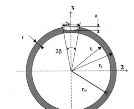
EDF, FRAMATOME and CEA have developed simplified methods to calculate the J integral in a pipe containing a circumferentially oriented surface crack. Figure 1 shows a semi-elliptical crack on the outside surface of a pipe. The crack
angle 13 is defined by" 13 = c ( 13 = c__ if the crack is on the inside surface).
re ri
These methods are currently available for mechanical loads (in-plane bending and torsional moments, pressure, tension), thermal loads as well as for the combination of these loads. They are gathered in Appendix 5.4.
,
r m
2f~
I
ESTIMATION OF THE J-INTEGRAL UNDER MECHANICAL LOADING
Two methods - named CLC and CEP - and derived from the R6 rule [8], are available for mechanical loads. Both methods are fully developed in the 2000 Addenda of the Code (appendix 5.4).
CLC method
The CLC method, based on a corrected limit load, will be shortly presented here (for the CEP method see [9].. The equation used to calculate Lr for a pressure combined with an in-plane bending moment is :
I E
m2
]2 I]2
L r
--
+
(1 _~ti
)__PP +~Lti
~ P (1)qm~lem~t
~ep
~ep
M2 ~ pr m
p = ~ ~ (2), (3)
where m2 and p are adimensional loading • m 2 4r2tSy 2 tSy
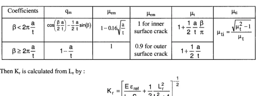
and qm, P, em, ~tt, #ep and ILtti are coefficients given in Table 1, depending only on geometrical parameters.
Table 1 - Coefficients for the CLC method
Coefficients
I ] < 2 = a
t
I ] > 2 = a
t
qm
cos(l , "sin
- 2 t ()a
1 t
~L~em
1 0.16~-~
~em
1 for inner surface crack
0.9 for outer surface crack
~t
1 a l l
1+
2 t =
1 a
1 + - - - - 2 t
~ti
~ti
~ t 2 - 1
l-t t
Then Kr is calculated from Lr by :
1
EEref -I
Kr = L r
Sy
2 L 2 +1 (4)w h e r e Ere f is the strain corresponding to the stress ~'ref-" Lr Sy o n the true stress - true strain curve of the material (same
approach as Option 2 of the R6 rule).
Finally, an estimation of the elastic-plastic J-integral is obtained by :
Je
J = ~
2
where Je is the elastic value of JKr
(5)
CEP method
The
C E P method [9] combines the elastic and fully plastic behavior through two equivalentstresses sigeqel
andSigeqp~,
1
olin T ogb
i~qel
_=
+ T . O g b + - + • .O'2m[sigeqpl]2 : Olin + T , Og b + _
+g
(6)
(7)
The value of the stresses (olin " axial membrane stress, (Y2m " circumferential membrane stress, Og b " global bending stress
Olin
/ ac)
P ri2 +-- E- ao ( re2 -ri2) 2
Table 2 - Values of stresses and coefficients for the C E P method
O2m
Ogb
rm M 2
P
= ~
t r : . r 2 .t
co -2T
-~-sin ~-13
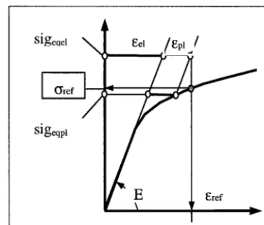
0.535 < g < 1The strains related to these two equivalent stresses are combined on the true stress-strain curve to determine the reference strain eref and the reference stress Ore f (Figure 2).
Sigeqel
eel ./l~pl /
] l ~ r e f
~
~
Sigeqpl
E Eref
Figure 2 - Reference stress evaluation
Finally, an estimation o f the elastic-plastic J-integral is obtained by :
Eeref J = J e " ~
Oref
(8)
C L C a n d C E P m e t h o d s
The CLC and C E P methods were validated thanks to a large database o f finite e l e m e n t results, comprising about 70 2D cases (axisymmetric cracks) and 70 3D cases (semi-elliptical cracks), see for e x a m p l e [10]. The following parameters were investigated •
- relative pipe wall thickness (t/rm = 1/5 or 1/10),
- crack location (inside or outside),
- r e l a t i v e crack depth (a/t = 1 / 8 ; 1/4 ; 1/2), - crack aspect ratio (a/c = 1/3 for most cases),
- marerial stress-strain curve ( R a m b e r g - O s g o o d fit with n = 5 or 8, 316 stainless steel, carbon steel with a plateau),
- type o f loading.
Parameter Value
rm (mm) 300
t (mm) 60
crack location outside
a (mm) 15
c (mm) 45
E (MPa) 177000
Table 3 - Characteristics of the cases presented
Parameter Value
v 0.3
Ramber~-Os~ood n Ramberg-Osgood t~
Ramberg-Osgood o0 (MPa) 120
0 to 5000 kN.m
Case 1 - L o a d i n g : M2
Case 2 - L o a d i n g : P + M2 0 to 21.2 Mpa, 0 to 5000 kN.m
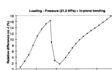
Figures 3 and 5 show the evolution of J at the deepest point of the crack as a function of Lr, whereas Fig. 4 and 6 show the evolution of the relative difference on J •
AJ / J (%)= 100 JRSE-M-JEF (9)
JEF
This type of analysis was conducted on the whole database, in order to determine an overall trend on the accuracy of the simplified methods. On most of the cases, the differences stay under 20 %.
Loading :In-plane bending
1600
--o- RSE-M 99 I
I
FE J
4) 400 A 1400 ~,1200 ° . , 01000
~
800600 ' U
200
0 l l
0,0 0,5 1,0 1,5 2,0 2,5
Lr
Figure 3 - Case I • Evolution of J as a function of Lr
Loading : In-plane bending
20 . . .
~ 1 5
g
~ 5
~ 0 J
0,5 1,0 1,5 2,0 2 Lr
-5 . . .
Figure 4 - Case 1 • Evolution of the relative difference on J
3500 E 3000 ~'2500 .c_ 0 =-2000 .1500 "0 1000
1~ 500
0,0
Loading : Pressure (21.2 MPa) + In-plane bending
-0-J RSE-M 99 -*-J FE
0,5 1,0 1,5 2,0 2,5
Figure 5 - Case 2 • Evolution of J as a function of Lr
Loading : Pressure (21.2 M P a ) + In-plane bending
18 . . . .
~ 8
~" 2
o
0,0 0,5 1,0 1,5 2,0 2,5
Lr
Figure 6 - Case 2 • Evolution of the relative difference on J.
ESTIMATION OF THE J-INTEGRAL UNDER THERMAL LOADING
A method is proposed to calculate J for an inside circumferential surface crack subjected to a cold thermal transient. It is
th th
assumed that the temperature distribution through the pipe wall and the elastic value of J - denoted J e - are known. J e can be obtained by an elastic analysis of the uncracked body and the use of influence coefficients.
First, a thermal strain eth is calculated :
eth = 0.85 4 f (10)
g0- )
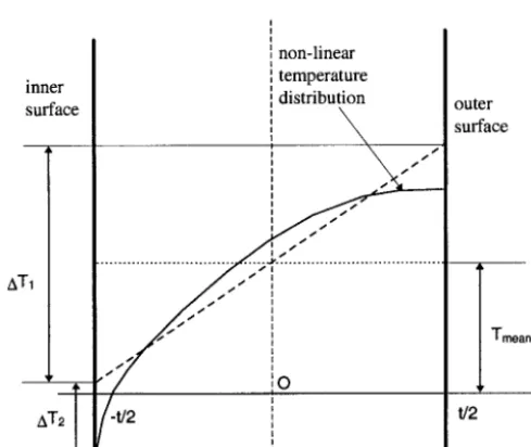
- where AT1 and AT2 are the values of ATI(t) and AT2(t) at the time of the transient when J ~ is maximum, - and f a parameter given in Table 4.
Table 4 - Values of the parameter f
a/t <1/30 1/16 1/8 1/4 1/3 1/2.5 1/2 f(a/t) deepest point 1 1.06 1.10 0.86 0.63 0.54 0.54 f(a/t) surface point 1.6 1.6 1.6 1.6 1.6 1.6 1.6
Figure 7 shows the definition of AT~ and AT2. They are respectively the linear thermal gradient and the non-linear thermal gradient defined in ASME Section III NB-3600 [ 11 ]. Their absolute value should be used in the above equation.
non-linear
• I temperature
:ner ] distribution outer
_ u @ ~ surface
I
I
x'., .-"
I t ... ... ,,r, I I / , , " "
Then an elastic-plastic corrective coefficient kth is determined by :
($ th _ 0 . 2 8 a th
k th -" Max 1.28 E e th E 13 th ( 1 1 )
L0.5
where C~th is the stress corresponding to the strain eth on the true stress - true strain curve of the material. Finally, an estimation of the elastic-plastic J-integral is obtained by :
Jth = k2h Jteh (12)
This method was also validated thanks to a large finite element results database, comprising mainly 2D cases (axisymmetric cracks).
E S T I M A T I O N OF THE J - I N T E G R A L UNDER C O M B I N E D L O A D I N G
A very simple method consists to add the elastic-plastic stress intensity factors (denoted Kj), respectively due to the mechanical loading and to the thermal loading :
th (13)
K j =K~ n +K~ h =K~ n + kthKi
However, this method is sometimes not conservative, as the stress systems interact. To take into account this interaction,
a parameter k th is introduced to calculate J •
[~/
* tJ~-e~ 12(14)
j = jm +kth
This parameter
k*
th is defined as follows •1) k*th = kth (no interaction) if at least one of the following conditions is verified : a)
Lr -< 0.5
b) Lr(P=0) < 2p
where - Lr(P=0) is calculated by the formula given for the mechanical loads with P = 0,
Pr m
- and p is the adimensional pressure previously defined ( P= 2 tS )"
Y
2) kth = 1 - 2p (1 k ) if neither of the above conditions a) and b) is verified. L r ( P = O ) - th
F L A W A S S E S S M E N T C R I T E R I A
The rules that are used to verify the acceptability of flaws in components habitually rely on deterministic criteria supposed to ensure the safe operation of plants. In order to have a reliable method of evaluating the safety margins, EDF conducted a study to link safety factors with safety levels [12], [ 13].
Based on a probabilistic calibration methodology, partial safety factors on the main random variables involved in flaw assessments (loading, crack size, yield strength and material toughness) are given in Appendix 5.5 of the Code for each category of operating conditions (A, C or D) and for the possible failure modes (plastic collapse, ductile tearing or brittle fracture). These partial safety factors should be used with the material characteristics specified in Appendix 5.6 of the Code, to insure the coherence of the methodology.
MATERIAL PROPERTIES
Appendix 5.6 of the Code gives data on the mechanical properties of main base-metals and welds used in primary and secondary systems of the NSSS. These data were developed by statistical analyses of both laboratory results and manufacturing data. A detailed presentation of this work is available in [16]. The components presently covered by the Appendix are as follows :
- reactor pressure vessel forged parts, - pressurizer forged parts and plates,
- steam generators parts (forgings and plates),
- main reactor coolant forged piping,
- secondary circuit piping (main steam lines and feedwater lines),
- the welds corresponding to each type of components. Three families of steel are used in these components :
- manganese-nickel-molybdenum low alloy steel (16 MND5 or 20 MND5, French standards similar to SA508 cl. 3 or SA533 gr. B),
- carbon-manganese steel (A42 or A48, French standards similar to SA106),
- austenitic stainless steel (Z3 CND 17-12 or Z2 CN 18-10, French standards similar to AISI 316L or 304L). The material characteristics included in the Appendix 5.6 of the Code are as follows :
- tensile properties comprising yield strength, ultimate tensile strength and adimensional reference true stress - true
strain curves,
- fracture toughness Kic and
Kjc
in the transition regime (low alloy steel),- value of the J-integral in the ductile regime at the onset of crack extension 00.2 after 0.2 mm of crack extension),
- J-Aa curves in the ductile regime,
- Fatigue crack growth rates.
CONCLUSIONS
The RSE-M Code provides rules and requirements for in-service inspection of French Pressurized Water Reactor power plant components. Its scope is close to the scope of Division 1 in Section XI of ASME.
The current state of the Code (2000 Addenda) in the field of flaw assessment procedures was presented in this paper. It is focused on fracture mechanics analyses based on simplified methods, flaw acceptance criteria and codification of material characteristics.
First, influence coefficients used to calculate the stress intensity factors in pipes and shells containing semi-elliptical surface defects are given for a wide range of the pertinent geometric parameters.
Secondly, simplified methods are proposed to calculate the J integral in a pipe containing a circumferentially oriented surface crack, submitted to mechanical or thermal loading.
Partial safety factors on the main random variables involved in flaw assessments (loading, crack size, yield strength and material toughness) are given for each category of operating conditions (A, C or D) and for the possible failure modes (plastic collapse, ductile tearing or brittle fracture).
Finally, mechanical properties of main base and weld materials used in primary and secondary systems of the NSSS are provided. These specified properties should be used for determining the acceptability of flaws that have been detected during in-service inspections.
NOMENCLATURE
ri Inside radius of pipe t~ Coefficient of thermal expansion
re Outside radius E Young's modulus
rm Mean radius v Poisson's ratio
t Pipe wall thickness Sy Yield stress
a Crack depth M2 In-plane bending moment
c Half-crack P Pressure
13 Half-crack angle ij Influence coefficient ( 0 < j < 3 )
Fb Shape factor for in-plane bending
REFERENCES
1. RSE-M Code, 1997 Edition and 2000 Addenda, "Rules for In-service Inspection of Nuclear Power Plant Components", AFCEN, Paris
2. ASME Boiler and Pressure Vessel Code, Section XI, Division 1, 1998
3. Barthelet, B., et al., 1995, "RSE-M Code progress in the field of examination evaluation and flaw acceptance criteria", Proc. SMIRT 13 Conference, Vol. II, pp. 647-652
4. Chapuliot, S., et al., 1998, "Stress intensity factors for internal circumferential cracks in tubes over a wide range of radius over thickness ratios", Proc. ASME PVP Conference, Vol. 365, pp. 95-106
5. Chapuliot, S., and Lacire, M.H., 1999, "Stress intensity factors for external circumferential cracks in tubes over a wide range of radius over thickness ratios", Proc. ASME PVP Conference, Vol. 388, pp. 3-12
6. Bergman, M., 1995, "Stress intensity factors for circumferential cracks in pipes", Fatigue Fract. Eng. Mater. Struct., Vol.
18, n°18, pp. 1155-1172
7. Raju, I.S., et al., 1982, "Stress intensity factors for internal and external surface cracks in cylindrical shells", J. of Press.
Vessel Tech., Vol. 104, pp. 293-298
8. Milne, I., et al., 1988, "Assessment of the Integrity of Structures Containing Defects", Int. J. of Press. Vessels and
Piping, Vol. 32, pp. 3-104
9. Papin, M.H., et al., 1997, "Evaluation of J on a pipe subjected to mechanical and thermal loading", Proc. SMIRT 14 Conference, Vol. 4, pp. 127-134
10. Barthelet, B., and Valeta, M.P., 1997b, "Elastic plastic fracture analysis of elliptical circumferential surface flaws in cylinders under pressure and bending", Proc. SMIRT 14 Conference, Vol. 4, pp. 135-142
11. ASME Boiler and Pressure Vessel Code, Section III, Division 1, Subsection NB, Subarticle NB-3600, 1998
12. Barthelet, B., and Ardillon, E., 1997a, "Simplified probabilistic approach to determine safety factors in deterministic flaw acceptance criteria", Proc. SMIRT 14 Conference, Vol. 4, pp. 553-560
13. Ardillon, E., Barthelet, B., and S#rensen, J., 1998, "Probabilistic calibration of safety factors for nuclear operating installations", Proc. ASME PVP Conference, Vol. 376, pp. 73-81
14. Bergman, M., et al., 1991, "Practical safety assessment of cracks in pressure vessels", Proc. ASME PVP Conference, Vol. 213, pp. 25-29
15. Sharpies, J., et al., 1999, "Developments in European defect assessment procedures", Proc. ASME PVP Conference, Vol. 392, pp. 217-223