2014/10/161
STRUCTURAL ZOOMING METHOD FOR THE SIMULATION OF
LARGE REINFORCED CONCRETE STRUCTURES
Antoine Llau1, Ludovic Jason2, Julien Baroth3, and Frédéric Dufour4
1PhD candidate, CEA, DEN,DANS,DM2S,SEMT,LM2S, 91191 Gif-sur-Yvette Cedex, France
Univ. Grenoble Alpes, 3SR, 38041 Grenoble Cedex 9, France
2Research engineer, CEA, DEN,DANS,DM2S,SEMT,LM2S, 91191 Gif-sur-Yvette Cedex, France
IMSIA, UMR 9219 CNRS-EDF-CEA-ENSTA, 91762 Palaiseau Cedex, France 3Associate professor, Univ. Grenoble Alpes, 3SR, 38041 Grenoble Cedex 9, France
CNRS, 3SR, 38041 Grenoble Cedex 9, France
4Professor, Univ. Grenoble Alpes, 3SR, 38041 Grenoble Cedex 9, France
CNRS, 3SR, 38041 Grenoble Cedex 9, France
ABSTRACT
Massive reinforced concrete structures, such as nuclear containment buildings, may undergo potential localized cracking when submitted to hypothetic loads in accident. This phenomenon is difficult to quantify by simulation because it requires nonlinear modelling at a refined scale, which cannot be applied on a large civil engineering structure. Therefore, focusing the computational effort on areas of interest, where cracking occurs, seems an interesting approach. This paper presents a structural zooming method that allows reducing the size of the nonlinear problem while still providing the same results as a full nonlinear computation. The method follows several steps at each load increment:
- Condense the undamaged areas (linear-elastic behaviour) and the associated loading (Guyan, 1965)
- Apply the computed equivalent stiffness and loading as boundary conditions for the areas of interest
- Solve the reduced problem (areas of interest and boundary conditions)
- Update the list of areas of interest depending on two criteria: deformation criterion on the condensed areas (based on nonlocal Mazars’ equivalent deformation) and damage propagation criterion on interfaces
This method is applied on the computation of two test cases: the first one represents a five meter reinforced concrete beam which has been experimentally tested under three-point loading (Ghavamian et al., 2003). The second one is a simplified and reduced model (nine meters height) of a reinforced concrete containment building under internal pressure. On both test cases, the computational effort is substantially reduced and the results (damage profile and mechanical response) are equivalent to the full nonlinear simulation.
INTRODUCTION
2000), but none actually addresses both issues of localizing and quantifying concrete cracking accurately on large-scale reinforced concrete structures.
In this communication, a new simulation method is presented, which allows to detect and quantify damage in concrete more finely than classical simulations for given computation resources. During the simulations, it detects areas where damage may appear and simulates it finely, while using a two-level condensation technique to avoid simulating undamaged areas. This method is presented in the first section, and applied on a reinforced concrete beam and a simplified containment building mock-up in the following sections.
ZOOMING METHOD
Principle
The approach proposed in this contribution focuses on large-scale structures such as containment buildings that undergo localized cracking risks or any kind of material damage. The main issue is to detect and quantify with a satisfying precision the damage in the structure. However this cracking risk is localized in areas that are small compared to the structure’s dimensions. The proposed method focuses on the local scale. It detects the areas where damage is likely to appear and condensates the rest of the simulated structure. This reduces the computational load and therefore enables the use of nonlinear models applied on a fine mesh in the areas of interest.
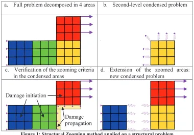
a. Full problem decomposed in 4 areas b. Second-level condensed problem
c. Verification of the zooming criteria in the condensed areas
d. Extension of the zoomed areas: new condensed problem
Figure 1: Structural Zooming method applied on a structural problem
Figure 1 presents the principle of the structural zooming method applied on simple structural problem divided in 4 zoomable areas. A full problem is decomposed in several areas (Figure 1.a: The problem is decomposed in 4 colored areas). Every area is condensed into an equivalent stiffness on its boundaries using Guyan’s method (Guyan, 1965). A pre-processing allows determining the first zoomed area from a criterion based on the elastic strain distribution. All other areas and the corresponding loading applied are then condensed again on the boundary of the zoomed areas, creating the second-level condensed problem (Figure 1.b: The yellow area is zoomed, all the others are condensed on its boundaries). The nonlinear
Damage initiation
simulation starts, with only the zoomed areas modelled. Periodically, two zooming criteria are tested respectively on the condensed and zoomed areas to check whether damage is likely to initiate in condensed areas, or spread from the zoomed areas (Figure 1.c: The initiation criterion is checked on all three condensed areas, the propagation criterion is checked in the yellow interface band between the zoomed and condensed areas). If one of those criteria is matched, the concerned area is zoomed and the remaining condensed areas undergo a new second-level condensation. A new condensed problem is created, and the simulation continues on this new problem (Figure 1.d: Damage appears in the blue area and propagates from the yellow to red area; the new condensed problem includes three areas).
Zooming Criteria
Zooming criteria used with the presented method depend on the mechanical models. Two zooming criteria have to be defined, corresponding to two different zooming situations:
- The initiation criterion is used to detect where and when damage will appear inside the (undamaged) condensed areas. It is computed using a linear resolution of the degrees of freedom in those condensed areas.
- The propagation criterion is used to detect where and when damage will propagate from the (damaged) zoomed areas to the (undamaged) condensed areas. It is directly extracted from the simulation results, and checked within a certain distance to the interface with other areas (the interface bands, Figure 1.c).
With Mazars’ model for concrete (Mazars and Pijaudier-Cabot, 1989), the initiation criterion is the value of Mazars’ equivalent strain
e
, which writes:(1)
With , , the principal values of the strain. This criterion’s threshold is the Yield limit of the material. If the model is used with a nonlocal method, the nonlocal equivalent strain
e
~ is to be used. In the case of reinforced concrete, it is assumed that concrete will be damaged before the appearance of plasticity in the steel rebars. For that reason, no zooming criterion is necessary on the steel mechanical model. Still with the Mazars model, the propagation criterion is the value of the scalar damageD
itself. A non-null damage value will imply zooming in the nearby area(s).REINFORCED CONCRETE BEAM UNDER THREE-POINT BENDING
Presentation
This test case represents a reinforced concrete beam that was tested under three-point loading during an experimental campaign (Pera, 1973), and used as benchmark case in project MECA (Ghavamian et al., 2003). The parallelepipedic beam measures 5 m length, for a height of 50 cm and width of 20 cm. The concrete has a compressive strength at 28 days of 38 MPa and a tensile strength of 3.7 MPa, for an elastic modulus of 3.7 GPa. It is reinforced with two Ø 32 mm steel rebars in its lower part, two Ø 8 mm bars in its higher part, and Ø 8 mm anti-shear stirrups every 20 cm.
an internal length lcof 5 cm. A reference simulation (in which the full structure is modelled) is run and compared to a simulation using the structural zooming method, with decomposition in 10 areas.
Results
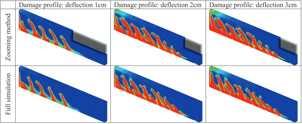
Load-deflection evolutions are presented in Figure 2 and show not only perfect correspondence between both full and zoomed simulation, but also a correspondence with the general shape of the experimental results. Also, the damage profiles displayed in Figure 3 exhibit a good correspondence between both simulations despite the difficulty to reproduce accurately that kind of local results.
Figure 2: Load-deflection evolution of the beam obtained with the full simulation, zoomed simulation and experimental results (Pera, 1973)
Damage profile: deflection 1cm Damage profile: deflection 2cm Damage profile: deflection 3cm
Zoom
ing
m
et
hod
Full
si
m
u
lat
ion
Figure 3: Damage distributions in the beam for the full and zoomed simulations at three stages of load
cracking would provide higher values of speed-up; however, the point of this method is to give access to higher refinement level for a limited computational load.
CONTAINMENT BUILDING MOCK-UP
Presentation
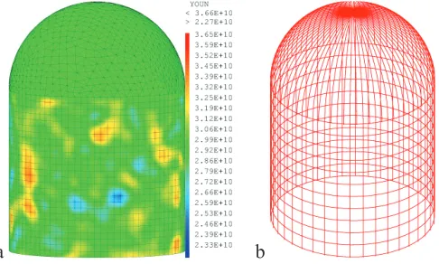
This test case represents a simple model for a reinforced concrete nuclear containment building mock-up. It consists in a cylindrical wall on top of which sits a hemispherical dome. The basis of the structure is blocked, and the building is loaded with an increasing internal pressure, representing the scaled mechanical solicitation of an eventual loss-of-coolant accident. Reinforcement bars are inserted in the concrete: the cylinder contains 12 horizontal and 40 vertical rebars, and the dome 80 vertical bars. Kinematic relations ensure the perfect steel-concrete bond. The concrete is modelled in three dimensions using Mazars’ scalar damage model, and the steel is modelled with truss elements, using von Mises’ plasticity model with linear hardening. The stress-based regularization method described in Giry et al., (2011) is used to avoid mesh dependency. A random field is used to fix the concrete’s elastic modulus, with a mean value of 30 GPa. A full simulation of the structure (the reference simulation) is run and compared to a simulation using the structural zooming method with decomposition in 12 areas. All simulations are run using Cast3M (CEA, 2014).
a b
Figure 4: a. Mesh of the concrete with random field of Young’s modulus.
b. View of the steel rebars in the concrete.
Results
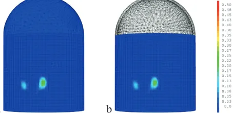
Pressure-displacement evolutions are presented in Figure 5 and show perfect correspondence between the zoomed simulation and the standard simulation; also, the damage profiles presented in Figure 6 display a total agreement of both computations: the results of the full simulation have been correctly reproduced.
Figure 5: Pressure-displacement evolution and zoom on the nonlinear phase
a b
Figure 6: Final damage distribution for the full (a) and zoomed (b) simulations
CONCLUSION
A method has been presented, that reduces the computational load of nonlinear simulations of large-scale reinforced concrete structures. It focuses the computational effort on the local-scale phenomena such as concrete cracking and reproduces the exact results of a complete simulation, for a reduced computation time. Ongoing research aims to extend this method to the simulation of large-scale prestressed concrete structures, and allow areas where damage does not evolve to be condensed again.
REFERENCES
CEA (2014). Description of the finite element code Cast3M [WWW Document]. URL http://www-cast3m.cea.fr/
Feyel, F., Chaboche, J.-L. (2000). “FE2 multiscale approach for modelling the elastoviscoplastic behaviour of long fibre SiC/Ti composite materials”. Computer Methods in Applied Mechanics and Engineering 183, 309–330.
Ghavamian, S., Carol, I., Delaplace, A. (2003). “Discussions over MECA project results”. Revue Française de Génie Civil 7, 543–581.
Giry, C., Dufour, F., Mazars, J. (2011). “Stress-based nonlocal damage model”. International Journal of Solids and Structures 48, 3431–3443.
Guyan, R.J. (1965). “Reduction of stiffness and mass matrices”. AIAA Journal 3, 380–380.
Haidar, K., Dubé, J.F., Pijaudier-Cabot, G. (2003). “Modelling crack propagation in concrete structures with a two scale approach”. International Journal for Numerical and Analytical Methods in Geomechanics 27, 1187–1205.
Pera, J. (1973). Reinforced concrete redundant beams. Theoretical and experimental analysis. INSA Lyon.