Modeling and Simulation of Hybrid Wind
Power Control for Load Sharing
M.Rupesh
1, A. Durga Prasad
2Shubha Kulkarni
3Assistant Professor, Department of Electrical & Electronics Engineering, GNDEC, Bidar, Karnataka, India1
Assistant Professor, Department of Electrical & Electronics Engineering, GNDEC, Bidar, Karnataka, India2
Assistant Professor, Department of Electrical & Electronics Engineering, GNDEC, Bidar, Karnataka, India3
ABSTRACT: Initially Wind Energy Conversion systems are usually passive systems i.e. the generated power is mainly dependent on the wind fluctuations but not on the grid requirements. An integrated DC-coupled wind, hydrogen and super Capacitor hybrid power system is studied in this paper. The main objective of this paper is to co-ordinate all these sources to share the (power) load in order to control the generated power, so control strategy for active wind generator is essential. The Active wind generator is built to provide some auxiliary services to the grid. The control strategy should be adopted to integrate the power sharing strategies. Two power sharing strategies are presented and compared by digital time domain Simulation studies in the MATLAB/ SIMULINK Software environment.
KEYWORDS: Distributed Power, Load Sharing, Hybrid Power System, Power Control, Wind Generator.
I. INTRODUCTION
Renewable energy Sources (RES) are much forwarded to read the following goals throughout the world.
1. Reduces the dependence of imported Fossil Fuel.
2. Reduces the pollution i.e. emission of greenhouse gasses.
During recent years the cost of fossil fuel is increased and efficiency is reduced, the controllability is the main drawback of RES like wind turbine and photovoltaic panels, because of these reasons the presence into the utility grid can lead to grid failure or grid instability if they are not properly controlled. More over integration of all these sources into one grid is very critical and required DG systems to provide those services like frequency and voltage regulations of the local grid. Wind energy is considered as RES in this paper, because wind energy is the world‟s fastest growing energy source, expanding globally at a rate of 25% - 35% annually over the last decade.
However, Wind energy conversion system is like passive generators because of fluctuations and intermittent wind speed, and they cannot offer any secondary services to electrical network in a microgrid, where stable active and reactive power requirements should be characterizes to the generators. To overcome these problems Hybrid power systems (HPS) are proposed with following two innovative improvements.
1. Energy Storage System may used to compensate or store the difference between the generated wind power and required grid power.
2. Power management strategies are implemented due to power exchange among different sources to provide load
sharing for the integrated grid.
II. RELATED WORK
Hydrogen technologies, combining fuel cells (FCS) Electrolyzers with Hydrogen tanks are most suitable for long term energy storage because of incomparable high mass energy density. In case of wind energy surplus, the excess energy is converted into H2 by Electrolyzer by electro chemical reaction. This H2 gas is stored in Hydrogen tank for future
utilization. When the generated wing energy is not satisfied by grid utilization, the stored electrolytic H2 can be used to
Recent progress in technology makes Super Capacitors are the best things as they are unique electrical storage devices that can store much more energy than conventional capacitors and offer high power density than batteries, it can changed very low time with a low current during stand by times between high current pulses globally SC‟s are having better round trip efficiency. Fly wheel systems are also suitable for fast dynamic energy storage; however, this mechanical system is currently hampered by the danger of explosive shattering of the massive wheel due to overload. SC‟s are less sensitive in operating temperature and have mechanical security problems.
In order to various technologies and advantages we have developed grid integrated wind generator (WG), including three kinds of sources.
1. Renewable energy sources i.e Wind Generator.
2. A fast dynamic storage i.e Super Capacitor.
3. Long term storage i.e FC,EL & H2 tank
For the control of internal power load sharing strategies should be developed in the control system to satisfy the grid requirements while maximizing the benefits of RES and efficient operation of each storage unit.
The purpose of this paper is to present the proposed load sharing strategies of the studied HPS in order to control the DC bus voltage and to respect the grid according to the microgrid power requirements. i.e. real and reactive power references, which are calculated by a centralized secondary control center on order to coordinate power dispatch or load sharing of several plants in a control area. In section III & IV, the studied HPS structure is presented, the structure of control system is adopted in order to integrate load sharing strategies. Two load sharing strategies are presented in section V. The simulation models and results are presented to compare their performances in section VI, Conclusions are given in section VII.
III. HPS & CONTROL SYSTEM
A) HPS Structure
DC- coupled structure is used in this paper to decouple the grid voltage and frequency from the sources. All the sources are connected to dc bus before connected to inverter shown in fig.1. each source is coupled electrically with a power electronic converter in order to power control action, and this HPS Structure. It‟s global control can be used for other combinations of sources also.
Fig.1. structure of the studied wind/hydrogen/SC HPS
B) Control System Structure
Fig.2. Hierarchical Control structure of the HPS
The Switching Control Unit (SCU) is for each power converter. In SCU, the drivers with optocouplers generate the ON/OFF signals from the ideal stage of switching function {0,1}, and the pulse width modulation determines the switching function from modulation function (m).
The Power Control Unit (PCU) is used for load sharing of entire HPS to satisfy the grid requirements. i.e. real and reactive power references which are obtained from secondary control center and drop controllers. In this some load sharing algorithms are implemented to co-ordinate the load flows of different energy sources. The different load sharing algorithms corresponds to number of possible operating modes of the HPS and can be gathered.
The Automatic Control Unit (ACU) is used for each energy source and power conversion system. The control algorithms of ACU calculate the modulation function (m) for each power converter through the regulation of some physical quantities according to their reference values. Some explanations of the ACUs are given in following paragraph.
C) ACU
The control schemes in the ACUs are shown in fig.3.
1. The EL Power Conversion System is controlled by terminal voltage (Vel) setting equal to a prescribed reference (
Vel-ref) through DC Chopper N 0
5. The EL stack is considered as an equitant current siurce (iel).
2. The FC Power Conversion System is controlled by taking fuel cell current ( ifc-ref) as reference through the DC
Chopper N04. The FC stack is considered as an equivalent voltage source (Vfc).
3. The SC Power Conversion System is controlled by reference current (isc-ref) through DC Chopper N 0
3. The SC bank is treated as an equivalent voltage source (Vsc)
4. The Wind Energy Conversion System is controlled by reference gear torque (Tgear-ref) of three phase rectifier
N02.
5. The Grid Connection System is consisting of a DC-bus Capacitors and grid power conversion systems, and is controlled with reference line current (il-ref) of three phase inverter N01, before grid transformer is treated as
equivalent voltage source (Vgrid) The DC bus Voltage is described as
𝐶𝑑𝑐 =𝑑𝑉𝑑𝑐
𝑑𝑡 = 𝐼𝑑𝑐 (1)
Fig.3.Modeling and Control of the HPS by the Energetic Microscopic Representation
IV. PCU
A) PCU Layout
There are two levels of power modeling in the HPS. i.e. power calculation level and the power flow level as shown in fig.4. Like that the PCU also divided into two levels. i.e. the power control level and load or power sharing level. The PCU enables the reference calculations for ACU from power references. The load sharing level coordinates the load flow exchanges among the different energy sources with different load or power balancing strategies. These are presented in fig.4. Multilevel representation.
i) Power Control Level
The power exchange with different sources can be controlled only by the related five references. (Vel-ref , ifc-ref, isc-ref,
Tgear-refand il-ref ) as shown in fig.5.Therefore the power equations are divided for power references as in table 1.for
energy storage systems, the powers are calculated by multiplying the measured currents and voltages (Int3, Int4 & Int5 in Table 1). The references of the controllable variables are obtained by dividing the power reference with the measured current or the measured voltages (Int3c, Int4c & Int5c in Table1).
To extract the maximum power from the wind energy conversion system, a maximum-power-point-tracking (MPPT) strategy is used with available wind energy according to a non-linear speed characteristic function. The control strategy receives the measured rotational speed (Ωtur) and sets a desired power reference (Pwg-ref) (Int2 & Int2c in Table 1). The
DC-bus voltage control loop output is the current ref (idc-ref) of the bus capacitor and the product with measured
dc-bus voltage gives the power reference ( Pdc-ref) for the dc-bus voltage regulation (Int0e) the exchangeable grid power
can be calculated by „two wattmeter‟ method (Int1 & Int1c in Table1).
To focus on power exchanges with different sources around the dc-bus, the instantaneously exchanged power with the choke, losses in filters and losses in power converters are neglected.
ii) Power / Load Sharing Level
The load sharing level is used to implement the power balancing strategies to coordinate the various sources in the HPS as shown in fig.4. it has very impartment role in the control system, because the power exchange affects directly the stability of HPS and impact the dc-bus voltage (Vdc).
𝑑𝐸𝑑𝑐
𝑑𝑡 = 𝐶𝑑𝑐𝑉𝑑𝑐 𝑑𝑉𝑑𝑐
𝑑𝑡 =
𝑃𝑑𝑐 = 𝑃𝑤𝑔 + 𝑃𝑠𝑐+ 𝑃𝑓𝑐− 𝑃𝑒𝑙− 𝑃𝑔 (2)
Where Edc: Stored energy in the dc-bus capacitor Pdc: Resulted power into the dc-bus capacitor Pwg: Generated power from the WG Pfc: Generated power from the FC Psc: Exchanged power with the SC Pel: Consumed power by EL Pg: Delivered power into the grid from the dc-bus Fig.4.Multilevel representation of the power modeling and control of the HPS The power flows inside the HPS are modeled with four equations with reference to power exchange. POW1: Pg = Psour - Pdc (3)
POW2: Psour = Psto + Pwg (4)
POW3: Psto = PH2 + Psc (5)
POW4: PH2 = Pfc – Pel (6)
Where
Psour: „Source‟ total power arriving of the dc-bus
Pstor: „Storage‟ total power arriving at the dc-bus
PH2: „Hydrogen‟ total power arriving at the dc-bus
In this wind / Hydrogen / SC HPS, five power electronic converters are used to regulate the power transfer with each source, According to a chosen power flow or load flow, the following two power balancing / load balancing strategies can be implemented.
1. The grid following strategy uses the line current loop to regulate the dc-bus voltage.
2. The source following strategy used the line current loop to control the grid active power and the dc-bus voltage is
V POWER/LOAD BALANCING STRATEGIES
A) Grid Following Strategy
In this control strategy the dc bus voltage is regulated by controlling the exchanged power with grid, while the WG
works with MPPT control strategies shown in fig.5. The dc-bus voltage control is shown by the closed loop (Pdc-ref – P
g-ref - Pg - Pdc). Thus, the required dc-bus voltage regulation power ( Pdc-ref) is used to estimate the grid power reference
(Pg-ref).
POW1e: 𝑃 𝑔−𝑟𝑒𝑓 = 𝑃 𝑠𝑜𝑢𝑟 - 𝑃 𝑑𝑒 −𝑟𝑒𝑓 (7)
The source total power (Psour) is a disturbance and should also be taken into account with the estimated wind power and
the sensed total storage power
POW2e: 𝑃 𝑠𝑜𝑢𝑟= 𝑃 𝑊𝑔+𝑃 𝑠𝑡𝑜 (8)
The energy stored system helps Wind energy conversion system to satisfy the power reference which is asked by microgrid operator.
POW3e:
𝑃 𝑠𝑡𝑜 = 𝑃 𝑠𝑐 +𝑃 𝐻2 (9)
POW4e:
𝑃 𝐻2 = 𝑃 𝑓𝑐 - 𝑃 𝑒𝑙 (10)
In steady state, the dc-bus voltage is regulated and the average power exchange with dc-bus capacitor can be considered as zero in (3). Hence in steady state the grid power (Pg) is equal to the total power from the sources (Psour). If microgris
system operator sets a power requirement (Pgc-ref) it must be equal to the sources power ref (Psour-ref) as shown in fig.5.
POW1C: Psour-ref = Pg-ref = Pgc-ref (11)
Fig.5. Multilevel representation of the grid following strategy
In order to help the wind energy conversion system respect the active-power requirement, the energy storage systems
should be coordinated to supply or absorb the difference between the power requirement (Pgc-ref) and the fluctuate wind
power (Pwg) as shown in fig.5.
POW2C: Psto-ref = Psour-ref = Pwg (12)
Among the energy storage systems the FC and the ELs are main energy exchangers, because a large quantity of hydrogen can be stored for enough energy availability, for efficiency reasons, the FC and EL should not work at the same time. The activation of FC or EL depends on the sign of the ref (PH2-ref). Thus, a selector assigns the power
reference (PH2-ref) to the FC (Pfc-ref) or to the EL (Pel-ref) according to the sign of PH2-ref shown in fig.5. POW4C:
𝑖𝑓 ∶ 𝑃𝐻2−𝑟𝑒𝑓 > ℰ, 𝑃𝑓𝑐 −𝑟𝑒𝑓 = 𝑃𝐻2−𝑟𝑒𝑓: 𝑃𝑒𝑙 −𝑟𝑒𝑓 = 0 𝑖𝑓 ∶∣ 𝑃𝐻2−𝑟𝑒𝑓 ∣≤ ℰ, 𝑃𝑓𝑐 −𝑟𝑒𝑓 = 0 ∶ 𝑃𝑒𝑙 −𝑟𝑒𝑓 = 0 𝑖𝑓 ∶ 𝑃𝐻2−𝑟𝑒𝑓 < − ℰ, 𝑃𝑓𝑐 −𝑟𝑒𝑓 = 0: 𝑃𝑒𝑙−𝑟𝑒𝑓 =∣ 𝑃𝐻2−𝑟𝑒𝑓 ∣
(13)
However, the power reference (Psto-ref) is a fast varying quantity with the fluctuant wind power (Pwg) and with the
varying grid power (Pg). To avoid the fast-chattering problem when it closes to zero, it should be slowed down.
welcome for their operating lifetime. Therefore, a low-pass filter (LPF) with a slope limiter should be added as shown in fig.6.
POW3c’: PH2-ref = 𝟏
𝟏+𝑻𝒔 ( 𝑷𝒔𝒕𝒐−𝒓𝒆𝒇) (14)
Where T is the time constant of the LPF and should be set large enough by taking into account the power dynamics of the FCs and ELs, as well as the size of the SCs. The SCs are not made for long-term energy backup unit because they have limited energy storage capacities due to their low energy density. However, they have very fast power dynamics and can supply fast varying powers and power peaks. They can be used as auxiliary power systems of the FCs and ELs to fill the power gaps during their transients.
POW3C:
𝑃𝑠𝑐−𝑟𝑒𝑓 = 𝑃𝑠𝑡𝑜 −𝑟𝑒𝑓− 𝑃 𝐻2= 𝑃𝑠𝑡𝑜 −𝑟𝑒𝑓− 𝑃 𝑓𝑐+ 𝑃 𝑒𝑙 (15)
The block diagram of the grid following strategy for the active WG is shown in Fig.6.
Fig.6. Block diagram of the grid following strategy
B) Source-Following Strategy
The total power (Psour) from the energy storage and the wind generator can also be used to provide the necessary total
power reference (Psour-ref) must be calculated by taking into account the required power for the dc-bus voltage regulation
(Pdc-ref) and the measured grid power (Pg) as disturbance input by using the inverse equation of POW1 as shown in
fig.7.
POW1c: Psour-ref = Pdc-ref + 𝑃 𝑔 (16)
Then, the total power reference of the storage system is deduced by taking into account the fluctuant wind power with the inverse equation of POW2 as shown in fig.7
POW2c: Psto-ref = Psour-ref - 𝑃 𝑤𝑔 (17)
The power reference is shared among the FCs, the ELs and the SCs in the same way as explained earlier (POW2c, POW4c, and POW’3c).
In addition, now, the grid power reference (Pg-ref) is free to be used for the grid power control, the microgrid system
operator can directly set the power requirements (Pgc-ref and Qgc-ref) for the grid connection system (Pg-ref = Pgc-ref).
Therefore, the HPS can directly supply the required powers for providing the ancillary service to the microgrid, like the regulations of the grid voltage and frequency.
Fig.8. Block diagram of the source following strategy
VI SIMULATION RESULT
A) Matlab Simulation Design
Matlab/Simulink model of HPS has been built to compare the different power / Load balancing strategies. Voltages and current generated by the power electronic converters are calculated, three boostcap SC models (160F & 48V) are connected in series. Therefore, the equivalent capacitor of the SC bank is about 53F, & the maximum voltage is 144V, all sources are connected to the dc-bus through different power converters. The dc-bus is connected to grid through three phase inverter, three line filters and a grid transformer.
The power / load balancing strategies are tested and compared respectively with the MATLAB SIMULATION test; it is possible to apply our proposed control system for the active generator and to test it with the developed power / load balancing.
B) Power Profile of Different Sources
Two tests are conducted by using MATLAB/SIMULINK for both strategies respectively. The same fluctuant wind
power profile is used during 150 s. the active power requirement from the microgrid is assumed to be Pgc-ref = 600W,
Similar power profiles are obtained from the energy storage systems as shown in Fig.10. When the generated wind power is more than 600W the EL is activated to absorb the power difference, but when the generated wind power is less than 600W the FC is activated to compensate the power difference. Since the power dynamics of the FC & EL are limited by an LPF with a 5-sec time constant, they are not able to filter the fast fluctuations of the wind power. Therefore, the SCs supply or absorb the power difference.
Fig.9.power profiles of different sources
C) Grid Following Strategy
In the grid following strategy, the dc-bus voltage is well regulated around 400V by the grid power conversion system as
shown in fig.11. the energy storage systems help the WG to supply the microgrid power requirement (Psour = Pge-ref =
Fig. 10.Grid following Strategy Simulation results
D) Source-Following Strategy
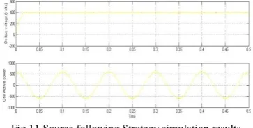
In the grid following strategy, the energy storage systems are controlled to supply or absorb the necessary powers in order to maintain the dc-bus voltage (around 400V) against the fluctuant wind power as shown in fig.12. the grid active power is also regulated and is equal to the microgrid‟s requirement, because the line current control loop regulates directly the grid powers (pg = Pgc-ref =600W). Therefore, the source following Strategy has better performances on the
grid power regulation than the grid following strategy, and it can provide ancillary services according to the microgrid‟s requirements.
Fig.11.Source following Strategy simulation results
E) Comparison and Discussion
The dc-bus voltage and the grid powers can be well regulated with both power balancing strategies, while the WG extracts the maximum available wind power.
By comparing the two power balancing strategies with their simulation results (Fig.11 & 12), we see that the grid active power is better regulated in the “grid following” strategy than in the “Source –following strategy” strategy. In the grid following strategy, the grid power varies continuously because the line control loop regulates the dc-bus voltage and the grid power is adjusted all the time. In the Source following strategy, the dc-bus voltage is regulated by the SCs, and the grid power can be directly used to supply the same power as required by the microgris system operator. Thus, if the active generator is required to provide the necessary powers to participate in the microgrid management, the source following strategy is preferred for more precisely controlling the grid powers.
VII. CONCLUSION
In this paper, a dc-coupled HPS has been studied with the three kinds of energy sources: 1) a WG as a renewable energy generation system; 2) SCs as a fast-dynamic energy storage system; and 3) FCs with ELs and hydrogen tank as a long term energy storage system. The structure of the control system is divided into three levels: 1) SCU; 2) ACU; and 3) PCU. Two power-balancing strategies have been presented and compared for the PCU: the grid following strategy and the source following strategy. For both of them, the dc-bus voltage and the grid power can be well regulated. The simulation results have shown that the source-following strategy has better performance on the grid power regulation than the grid-following strategy.
REFERENCES
[1] W. Li, G. Joos, and J. Belanger, “Real-time simulation of a wind turbine generator coupled with a battery supercapacitor energy storage system,” IEEE Trans. Ind. Electron., to be published.
[3] M. Little, M. Thomson, and D. Infield, “Electrical integration of renewable energy into stand-alone power supplies incorporating hydrogen storage,” Hydrogen Energy, vol. 32, no. 10, pp. 1582–1588, Jul. 2007.
[4] T. Zhou, D. Lu, H. Fakham, and B. Francois, “Power flow control in different time scales for a wind/hydrogen/super-capacitors based active hybrid power system,” in Proc. EPE-PEMC, Poznan, Poland, Sep. 2008,pp. 2205–2210.
[5] R. Cardenas et al., “Control strategies for power smoothing using a flywheel driven by a sensorless vector-controlled induction machine operating in a wide speed range,” IEEE Trans. Ind. Electron., vol. 51, no. 3, pp. 603–614, Jun. 2004.
[6] J. M. Guerrero, J. C. Vasquez, J. Matas, M. Castilla, and L. G. de Vicuna,“Control strategy for flexible microgrid based on parallel line-interactive UPS systems,” IEEE Trans. Ind. Electron., vol. 56, no. 3, pp. 726–736, Feb. 2009.
[7] C. Sudipta, D. W. Manoja, and M. G. Simoes, “Distributed intelligent energy management system for a single-phase high-frequency AC microgrid,” IEEE Trans. Ind. Electron., vol. 54, no. 1, pp. 97–109, Feb. 2007.
[8] T. Zhou, P. Li, and B. François, “Power management strategies of a DC- coupled hybrid power system for microgrid operations,” in Proc. 13th Int. Eur. Power Electron. Conf. Exhib. EPE, Barcelona, Spain, Sep. 2009, pp. 1–10, [CD-ROM].
BIOGRAPHY
M. RUPESH received the M.Tech Degree in Power system Control & Automation From Jayamukhi Institute of Technological Sciences JNTUH),,iin 2013.completed B.Tech Degree in Electrical & Electronics Engineering from B.V.Raju Institute of Technology, JNTUH and presently working as Asst. Prof. In Guru Nanak Dev Engineering College, Bidar His Interests Include DG‟s , Microgrids And Power System Operation & Control
A.Durgaprasad received the M.Tech Degree in Power Electronics From JNTUH and obtained B.Tech Degree in Electrical & Electronics Engineering from JNTUH and presently working as Asst. Prof. In Guru Nanak Dev Engineering College, Bidar His area of Interests Include Renewable sources of energy , power electronics and drives.