Vol. 4, Issue 2, February 2015
Investigating The Possibility Of Recognizing
The Forgery By Using Spatial & Transform
Domain
Joshi Chintal J, Prof. Shailendra KMishra
Department of Computer Science Engineering, Parul Institute of Technology, Gujarat, India
Department of Computer Science Engineering, Parul Institute of Technology, Gujarat, India
ABSTRACT: This paper reveals basics of Digital (Image) Forensics.One of the most successful application digital image forgery detection has recently received significant attention, especially during the past few years. At least two trend account for this: the first accepting digital image as official document has become a common practice, and the second the availability of low cost technology in which the image could be easily manipulated. Even though there are many systems to detect the digital image forgery, their success is limited by the conditions imposed by many applications. Most existing techniques to detect such tampering are mainly at the cost of higher computational complexity.Copy-Move forgery is a specific type of image forgery,in which a part of digital image is copied and pasted to another part in the same image. In this paper we propose a method to detect duplicatedregions in an image using using Zernike moments. By using Zernike moments we can detect duplicatedregions even if they scaled or rotated, but these features cannot find flat duplicated regions. Zernike moments can solve thisproblem; we will apply Zernike moments on such regions, So duplicated region in all over the image even in flat regions will detected while the process time isefficient.Then works by first applying DWT (Discrete Wavelet Transform) tothe input image to yield a reduced dimension representation. Then the compressed image is divided into overlapping blocks.These blocks are then sorted and duplicated blocks are identifiedas similarity criterion. Finally, the feature vectors are lexicographically sorted, and duplicated image blocks will be matched.
KEYWORDS:Digital image forensic; Image forgery;Region duplication; Copy-paste forgery detection; Block based; Zernike Moment; Spatial Domain; Transform Domain; DWT;
I. INTRODUCTION
1.1 DIGITAL FORENSIC INVESTIGATING THE IMAGE FORGERY
Vol. 4, Issue 2, February 2015
number of forgery images have recently been distributed or have even been published by major newspapers. Therefore, it is important to verify the authenticity of digital images. Forgery techniques using typical, copy-move forgery is one of the most commonly used methods. The copy-move forgery copies a part of the image and
pastes it into another part of the image to conceal an evidence or deceive people.
1.2 INTRODUCTION TO IMAGE FORGERY
Image forgeryhistory has recorded that is happen on early as on 1840. Hippolyta banayrd, the first person to create fake image. Image forgery is defined as “adding or removing important features from an image without leaving any obvious traces oftampering”, [56]. In terms of Digital image processing, forgery can be defined as changing original image information by modifying pixel values to new preferred values so that the changes are not perceivable. This means enhancing an image by forgery image in order to clearly express the information content of the image should not be taken as forgery, but forgery to deliberately digital images from their time of capture with an intention to change its original information is called digital image forgery. It is also called as image forgery. The picture left in Figure 1 below is a spectacular image of a "triple tornado" accompanying Hurricane Lilli, which made landfall in Louisiana in early October 2003. However, the same image appeared on page 8 of the fall 2002 issue of Anchor Lines news letter. The original image was taken in the Gulf of Mexico back in June 2001 by acrewmember of the C-Rambler, a 240-foot supply boat. Someone manipulated the original and turned it into a photograph of three waterspouts, a picture that began circulating as an amazing image of a triple tornado associated with the storms of Hurricane Lili in October 2002.
Figure 1: example of C-RAMBLER with a single tornado in the back (left), forged image with 3 tornados (right)
1.3 DETECTION OF COPY- PASTE IMAGE FORGERY
Vol. 4, Issue 2, February 2015
measure in different parts of the image. The easiest way to detect such image forgery is trivially the exhaustive search, but this approach has two major drawbacks: 1) It is computationally costly for large images since it takes MN2 steps for an image of size M × N and 2) It fails to detect the forgery in case the copied portion has undergone some modifications. A second and more efficient approach, which was proposed by Fridrich et al. in [57], is the use of autocorrelation properties. Nevertheless, this approach was shown to fail in case the duplicated region is not a large portion of the original image.
Figure2. An example of image forgery that appeared in press in July, 2007. The forged image (on the right) shows four Iranian missiles but only three of them are real; two different sections (encircled in red and purple, respectively) replicate other image sections by applying a copy-paste attack.
1.3.1 Copy paste forgery detection
Figure. 3 Detecting image regions forged using the clone brush: (a) the original, image, (b) the forged image, and (c) the detected regions
To the best of our knowledge, this survey is the most complete in the field of partition-based copy-move forgery detection approaches. Based on the foregoing, the latter approaches can be divided into main classes depending upon the partitioning plan. We will classify as block-based approaches the approaches that uniformly partition the image into small overlapping/nonoverlapping rectangular or circular partitions called “blocks” of fixed size.
II. BLOCKBASEDDETECTIONOFCOPY-PASTEFORGERYMETHOD.
Block based methodis the regions of the image covered by thematching blocks are the copied and forged regions.And subdivided image into blocks for feature extraction and feature vector matching is lexicographical sorting is used; it is can detect the large transformation. More memory required & consequently more computation time and more accurately detect duplication region in image forgery.
Vol. 4, Issue 2, February 2015
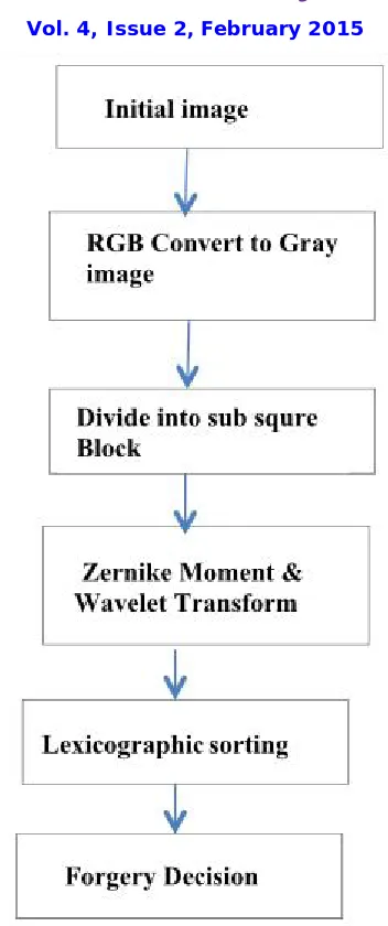
Figure 4. Common pipeline for block-based detection of copy-move forgeries.
Steps for block based detection of copy move forgery
1) Step
Firstly, takes as an initial input image and then it checks that whether it is RGB or gray image. If the input image is RGB, it converts the same into grey scale image.
2) Step
Vol. 4, Issue 2, February 2015
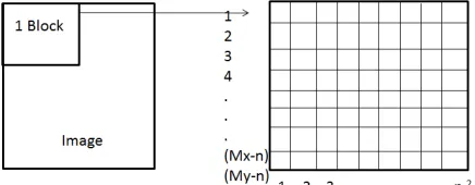
either square or circular.Square blocks arethe image is divided into overlapping/nonoverlapping square blocks by sliding once along the image a window of size b × b from the upper left corner right down to the lower right cornerof the image.
Figure 5. overlapping Square block 4 x4 block division.
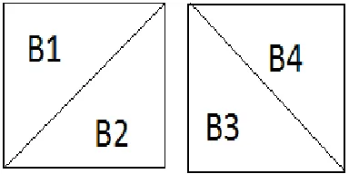
The image reduced is divided into all possible blocks of b pixels. And the Block is stored in feature vector of matrix. The size of the matrix is (M-B+1) x (N-B+1) rows and B x B columns, where M and N are the number of rows and columns of the chosen image respectively.We have divided four blocks diagonally separately for both diagonals as shown in figure 5.
Figure 6. Divided four blocks diagonally separately for both diagonals.
By dividing a block in such manner we get some good features which are highly related. Suppose I have eight block & Matrix containing feature vector. For each Block, Bp = 1,2,3,4,...,8 & feature vector Vp = 1,2,...,8. Then I will calculated.
Features vector are calculated according to following equations are:-
Vp =
First feature vector p is calculated by averagingpixels of sub block middle (B). These pixels are those which reside in a square block with side b*L and with centre same as of the original block where L is a real number between 0 and 1. There is no hard and fast rule of calculating the optimum value of L, but this is expected to be between 0.65 and 0.99. By doing so we can have a better result because generally border of copied area is more forgery. Feature vectors are
Average of middle(B) p = 1
Vol. 4, Issue 2, February 2015
calculated by taking the ratio of the average of pixel value of sub block and the average of pixel value of block B. These feature vectors are efficient for certain operations. It is good for Gaussian Noise addition. Next feature vector can be calculated by taking difference between average of pixel values of each sub block and whole block. These features help in giving very good results for constant smoothing. After calculating all the feature vectors, it should be normalized in the range of (0,255). Radix sort is applied on these features.
1) Step
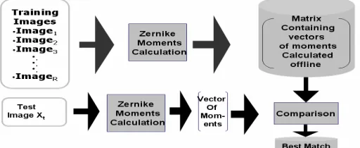
Zernike Moments for image analysis were originally introduced in the 1960s byHu. Using nonlinear combinations of regular moments (also referred to as geometric moments); he derived a set of invariant moments, which have the desirable properties of being invariant under image translation, scaling, and rotation. Let we have images training the system, the vectors of moments for these images from the zeroth order to the highest order are calculated and stored in a database. The vector of moments for the test image is also calculated and compared with the stored vectors on the database for finding the best match. The Image forgery recognition process using ZMs. Zernike moment can be used to detect flat copied or duplicate region. This method, they were able to reduce false alarms because they considered that image is forged only when two block are matched with a minimum of three similar feature blocks. However, thisfeature reduces the possibility of detecting flat forgeries. Their method was able to find out the possible geometric transformations performed. To account for flat forgeries, Zernike moments are used.Tthey divided the image into several sub-blocks and calculated Zernike moments. This involves complex calculations and at the end a feature vector with coefficients of Zernike moments is obtained. With respect to certain threshold values, they determined matching blocks. For each block, Zernike moments of precise order are computed and arranged in a vector. Blocks will be characterized by the magnitude values of the obtained vectors. The method is robust to rotation and noise contamination.Zernike Moments have also found a in the region of forged image recognition, since they describe the shape objects.
Figure 7. image forgery recognition steps using Zernike moment
ZMs are a class of orthogonal moments that are effective in terms of image representation. They are based on orthogonal Zernike radial polynomials. These moments are effectively used for pattern recognition since their rotational invariants can be easily constructed to an arbitrary order. The face recognition system based on ZMs proceeds as follows. The ZM vectors of the training images are calculated and stored in a database. For an manipulate or forged image to be identified; its vector of moments is also calculated and compared with the stored vectors to find the closest match.Zernike moments are a set of complex polynomials, it is a complete orthogonal set defined in the polar coordinates over the interior of the unit circle. Image feature vector are extracted by the image forged duplicate region mapping the image into a set of orthogonal basis functions defined over the unit circle. These features are the magnitudes of complex ZMs. Also they keep their magnitude constant at anyrotation.The orthogonal property of ZMs makes the forged image reconstruction from its moments computationally simple. It enables one to evaluate the image representation ability of each order moment as well as its contribution to the reconstruction process.The complex ZMs of order n with repetition rare defined as:
Vol. 4, Issue 2, February 2015
where n=0,1,2,…,∞ denotes the order of the moment and r denotes the repetition , where 0 ≤│r │≤n and n-│l│is even. The symbol * denotes the complex conjugate, and the circular Zernike polynomials Znr are defined over a unit circle as:-
where Rnr(r) is the radial polynomial, (r) is the length of the vector from the origin to (x,y) pixel, and θ is the angle
between the radial vector r and the x axis in counter-clockwise direction.
The real-valued radial polynomials, are given by:-
Eq. (3)
These polynomials are orthogonal within the unit circle, so the analyzed shape of the area of interest has to be remapped to be of the same size before calculation of its moments. This implies difficulty in mapping a unit circle to a Cartesian grid. To compute the ZMs of a given image, the center of the image is taken as the origin and pixel coordinates are mapped to the range of unit circle, i.e., x2 + y2 ≤ 1. The pixels falling outside the unit circle are not
used in the computation.
Figure. 7. The circle can be within the area of interest, losing corner information as in Fig. 6.a); or around the area of interest, which then covers areas, where there is no information, but ensures that all the information within the area of interest is included as in Fig. 6.b.(53)
• The Zernike moment of an image is defined as:=
Eq.( 4)
The orthogonal of these polynomials assures the reduction in the set of numbers used to describe a shape. The number of ZM for any order, n, is given by n+1, while the number of moments up to and including order n is given as:-
Eq.( 5)
The Euclidean distance between two adjacent pairs of Z calculated. If the distance is smaller than the pre-defined threshold D1 we consider the inquired blocks as a pair ofcandidates for the forgery: The Euclidean distance between two adjacent pairs of Z calculated. If the distance is smaller than the pre-defined thresholdD1 we consider the inquired blocks as a pair ofcandidates for the forgery:
^ ^ p ^p ^p ^p
Vol. 4, Issue 2, February 2015
Zp= ( Z1 , Z2,...Znmoment-1 , Znmoment),
^ ^ p+1 ^p+1 ^p+1 ^p+1 Zp+1= ( Z1 , Z2,...Znmoment-1 , Znmoment),
Eq. (6)
The neighboring blocks might result in relatively similar Zernike moments, we calculate the distance between the actual blocks of the image as follows:
( − ) + ( − ) >D2 Eq. (7)
Zp = Vij and Zp+1 = Vkl
2.1 Properties of ZMs
The Zernike moment functions have the following properties:
• Rotation Invariance
ZMs based techniques are rotation invariant because they use the magnitudes of ZMs as descriptors for image representation and recognition.
• Robustness
ZMs are robust to noise
• Expression Efficiency
ZMs are based on orthogonal functions, there is no information redundancy.
• Effectiveness
An image can be better described and reconstructed by a small set of its ZM than any other types of moments, such as geometric moments, Legendre moments, rotational moments, and complex moments in terms of
mean-square error.
• Multilevel Representation
A relatively small set of ZMs can characterize the global shape of a pattern, electively. Lower order moments represent the global shape of a pattern and higher order moments represent the details.
It is a well-recognized property of moments that they can be used to reconstruct the original function, i.e. none of the original image information is lost in the projection of the image on to the moment basis functions, assuming an‘infinite’ number of moments are calculated]. For non-orthogonal moments, the reconstruction is not straightforward and requires a moment-matching. Suppose that we knows all moments Anr of f (x, y) up to a given order nmax. It is desired to reconstruct a discrete function f (x, y) , whose moments exactly match those of f (x, y)up to the given order nmax. ZMs are the coefficients of the image expansion into orthogonal Zernike polynomials. By the orthogonal property of the Zernike basis :-
Eq. (8) Wavelet transform
Vol. 4, Issue 2, February 2015
vector is built by computing the mean, the sum of the absolute values, the square root of the squared values' sum, the standard deviation, and the average residual of the pixels in the block. The method is robust to blurring and edge sharpening operations.
This methods works by first applying DWT to the input image to yield a reduced dimensional representation. Then the compressed image is divided into overlapping blocks. These blocks are then sorted and duplicated blocks are identified using Phase Correlation as similarity criterion. DWT usage, detection is first carried out on lowest level image representation.
1) Step
Detecting copy-move forgery in an image in extensive search of region matches [58]. Preliminary idea that one gets to detect copy-move forgery is breaking an image spatially in to blocks of size n * n and comparing the blocks for matches. The block size taken should be smaller than the minimum size of assumed forgery. If a part of image is copied and pasted at a different position in to the same image from which it has been derived, it is the forgery introduces correlations between the segment copied and the pasted one. This kind of correlation can be detected by extensive search for similar segments or pixel blocks in the whole image. Let the image to be investigated is of N pixels with a width of Mx pixels and a height of My pixels. Let the minimum copy-move image forgery size be greater than a block of n*n pixels. The image is split into a number of blocks.This is done by scanning the image at every pixel location with an n * n block and extracting pixel values either column or row wise into rows of a two dimensional array. For each block we get eight feature vectors. V= v1,v2,v3,v4,v5,v6,v7,v8. All these are stored in an array A.This row and column of the starting pixel of this block. This array has columns and rows. First eight columns will be used in sorting. Since features are normalized for the integers so Radix sort is efficient method [comp12]. The highest priority is given to feature V1, then the features from V2 to V5 and least for the features V6 to V8. The main advantage of sub blocking the blocks in the form of diagonals is that one pixel is contributing in two different sub blocks. So it gives strongly correlated features.The index of each pixel block in the array indicates the position of the pixel starting from where the block is extracted from the image. Once the image data is gathered into the array, all the rows are compared with all other rows to find matches. If two rows are identical it is likely to have two identical patterns of block in image. One way of reducing the search duration is by sorting the array in lexicographical order and searching from top to bottom of the array for find identical rows.
Copy-move pairs are identified by searching the blocks with similar feature vectors. The extracted features are first arranged as rows of a matrix M. Then, the trivial approach is to compare each feature with all the other features but this is expensive in terms of computation time. In fact, each feature will only be compared with a certain amount of its neighbours. Among the known methods, the most commonly used is lexicographic sorting [54] that consists of row-sorting M lexicographically to produce a resulting matrix having similar features adjacent to each other, and consequently making them easier to detect.
Lexicographic sorting find the similar block. Once the elements of the 2D array are sorted in lexicographic order and analyzed, all the rows of the array are compared for matches. Shift value are seperate the list. matches and shift’s depend on the number of copy-move image performed and the size of the forgery region. More shift value with equal value indicate forgery rather than random shift values.
Vol. 4, Issue 2, February 2015
3) Step
The single similarity criterion is not enough to decide on the presence/absence of duplicated region. This is due to the fact that most original image might contain one or more pairs of highly similarregions, consequently false matches. There is a need to identify characteristics of copy-moved regions to distinguish them from falsely matched ones. Using the shift vector between the coordinates of every matched pair of feature vectors adjacent pairs in case of lexicographic sorting .It is supposed that all the copy-move pairs must have the same displacement vector. The accumulated number of each of the shift vectors is then computed and the large accumulated number is considered as eventual presence of a duplicated region.
Detection of duplicate regions: - Array is sorted, and then the rows, representing blocks with very similar features, are arranged nearly. For every pair of continous rows which are representing the features of the two respective blocks, we find logical distance between these two features, where each feature is considered as an independent dimension. When the logical distance is found to be less or equal to a pre-set threshold T1 and the physical distance between the block regions is greater of equal to a pre-set threshold T2, a copy move activity in the corresponding blocks is suspected.
Neighbor Shift Matching: For a suspected pair of blocks, the system compares features of nearby blocks of both of the blocks of a pair which are at the same vector distance from the corresponding block.
III. USING SPATIAL AND TRANSFORM DOMAIN
3.1 Spatial Domain
In this image is divided into blockd of size n*n and comparision is done on the actual pixel values. Then the Analysis performed in Spatial Domain. It is Much faster.
3.1.1 Method
The value of a pixel with coordinates (x,y) in the enhanced image is the result operforming some operation on the pixels in the neighbourhood of (x,y) in the input image, F. Neighbourhoods can be any shape, but usually they are rectangular.
1) Grey scale image manipulation
The simplest form of operation is when the operator T only acts on a 1×1 pixel neighbourhood in the input image, that
is only depends on the value of F at (x,y). This is a grey scale transformation or mapping.
The simplest case is thresholding where the intensity profile is replaced by a step function, active at a chosen threshold value. In this case any pixel with a grey level below the threshold in the input image gets mapped to 0 in the output image. Other pixels are mapped to 255.
2) Histogram Equalization
Histogram equalization is a common technique for enhancing the appearance of images. Suppose we have an image which is predominantly dark. Then its histogram would be skewed towards the lower end of the grey scale and all the image detail is compressed into the dark end of the histogram. If we could `stretch out' the grey levels at the dark end to produce a more uniformly distributed histogram then the image would become much clearer.Histogram equalization involves finding a grey scale transformation function that creates an output image with a uniform histogram (or nearly so).
3.2 Transform Domain
Vol. 4, Issue 2, February 2015
method on the kind of analysis performed on the collected data can be classified as DWT, DCT DFT, and DST. It is more computational complexity involve in the process. Nice robustness to common post processing operation. Works even for the images where the attacker has made detection more difficult by applying noise & JPEG quality level changes.The idea of blurring an image by reducing its high frequency components or sharpening an image by increasing the magnitude of its high frequency components is intuitively easy to understand. However, computationally, it is often more efficient to implement these operations as convolutions by small spatial filters in the spatial domain. Understanding frequency domain concepts is important, and leads to enhancement techniques that might not have been thought of by restricting attention to the spatial domain.
3.2.2 Method
1) Matching quantized dct coefficients (dct):
Spatially analysing local regions of pixel data, analysis is performed in frequency domain by calculating quantized DCT coefficients for the pixel blocks and searched for matches among the blocks.
2) Matching dwt blocks (dwt):
This methods works by first applying DWT to the inputimage to yield a reduced dimensional representation .Then the compressed image is divided into overlapping blocks. These blocks are then sorted and duplicated blocks are identified using Phase Correlation as similarity criterion. Due to DWT usage, detection is first carried out on lowest level image representation.
3) Filtering
Low pass filtering involves the elimination of the high frequency components in the image. It results in blurring of the image (and thus a reduction in sharp transitions associated with noise). An ideal low pass filter would retain all the low frequency components, and eliminate all the high frequency components. However, ideal filters suffer from two problems: blurring and ringing. These problems are caused by the shape of the associated spatial domain filter, which has a large number of undulations. Smoother transitions in the frequency domain filter, such as the Butterworth filter, achieve much better results.
Homomorphic filtering
Images normally consist of light reflected from objects. The basic nature of the image F(x, y) may be characterized by two components: (1) the amount of source light incident on the scene being viewed, and (2) the amount of light reflected by the objects in the scene. These portions of light are called the illumination and reflectance components, and are denoted i(x,y) and r(x,y) respectively. The functions i and r combine multiplicatively to give the image function F:
F(x,y) = i(x,y)r(x,y).
III.CONCLUSION
Vol. 4, Issue 2, February 2015
REFERENCES
1. Christlein, C Riess, J Jordan, C Riess, E Angelopoulou, An evaluation of popular copy-move forgery detection approaches. IEEE Trans. Inf. Forensics Secur7(6), 1841–1854 (2012)
2. X Pan, S Lyu, Region duplication detection using image feature matching. IEEE Trans. Inf. Forensics Secur5(4), 857–867 (2010)
3. Amerini, L Ballan, R Caldelli, A Del Bimbo, G Serra, A SIFT-based forensic method for copy move attack detection and transformation recovery. IEEE Trans. Inf. Forensics Secur6(3), 1099–1110 (2011)
4. DG Lowe, Distinctive image features from scale-invariant keypoints. Int. J. Comput. Vis 60(2), 91–110 (2004)
5. R Böhme, M Kirchner, Counter-forensics: attacking image forensics. Digital Image Forensics (Chapter 10), ed. by Sencar HT, Memon N (New York: Springer,, 2012)
6. RC Veltkamp, M Tanase, Content-based image retrieval systems: a survey. Technical report, Utrecht University (2002)
7. CY Hsu, CS Lu, SC Pei, Secure and robust SIFT. Proceedings of the 17th ACM International Conference on Multimedia, MM ’09 (New York: ACM,, 2009), pp. 637–640
8. A D’Angelo, M Barni, A structural method for quality evaluation of desynchronization attacks in image watermarking. Proceedings of the IEEE 10thWorkshop on Multimedia Signal Processing (Piscataway: IEEE,, 2008), pp. 754–759
9. AAFS. (1996) “What is Forensic Science?” [online], AmericanAcademy of Forensic Sciences, http://www.aafs.org/Eoghan Casey , Handbook of Computer Crime Investigation: Forensic Tools and Technology, Second Edition, Academic Press, 2003.Department of Justice, computer crime and intellectual property section,[Online]. Available:http://www.usdoj.gov/criminal/cybercrime/searching.html
10. Digital Forensic: Electronic evidence collection, examination & analysis bu using combine moments in spatial & transform domain Hani saleh, Sosagaian, KhadermohamdIEEE Internationalconference on system, man &cybernetics(october-2009)
11. R. Böhme and M. Kirchner, “Counter-forensics: Attacking imageforensics,” in Digital Image Forensics, H. T. Sencar and N. Memon,Eds. New York, NY, USA: Springer-Verlag, 2012,
12. Amerini, L. Ballan, R. Caldelli, A. D. Bimbo, andG. Serra, “A SIFT-based forensic method for copy–move attackdetection and transformation recovery,” IEEE Trans. Inf. ForensicsSecurity, vol. 6, no. 3, pp. 1099–1110, Sep. 2011.
13. Automated Forensic Method for Copy-Move ForgeryDetection based on Harris Interest Points andSIFT DescriptorsB.L.Shivakumar, Department of Computer Applications, S.N.R. Sons College Coimbatore – 641006, TamilnaduDr. S.SanthoshBaboo, PG & Research Dept. of Computer Applications D.G.Vaishnav College ,Chennai – 600106, Tamilnadu , International Journalof Computer Applications (0975 – 8887) Volume 27– No.3, August 2011
14. Robust Copy Move Image Forgery Detection using Scale Invariant Features TransformInternational Journal of Computer Applications (0975 – 8887) Volume 97– No.10, July 2014Himanshu Goyal,TarunGulati
15. Amerini, M. Barni, R. Caldelli, and A. Costanzo, “Counter-forensicsof SIFT-based copy-move detection by means of keypoint classification,”EURASIP J. Image Video Process., vol. 2013, no. 1, p. 18, 2013.
16. Khotanzad A. and Hong Y.H., Invariant image recognition by Zernike moments, IEEE Transactions on Pattern Analysis and Machine Intelligence, 489 -497, 1990.
17. S. Lyu and X. Pan, “Detecting image region duplication using SIFT features,” IEEE ICASSP, Dallas, USA, 2010
18. S. Bayram, H. T. Sencar and N. Memon, “A Survey of Copy-Move Forgery Detection Techniques,” in IEEE Western New York Image Processing Workshop, New York, September 2008.
19. D. Lowe, “Distinctive image features from scale-invariant keypoints,” International Journal of Computer Vision, vol. 60, no. 2, p. 91–110, 2004. 20. Frequency Domain Watermarking: An OverviewKhaled Mahmoud, SekharjitDatta, and James FlintDepartment of Electrical and Electronic
Engineering, Loughborough University, UK. The International Arab Journal of Information Technology, Vol. 2, No. 1, January 2005
21. Tampering and Copy-Move Forgery Detection Using Sift FeatureDr.SivanthiAditanar College of Engineering,Tiruchendur, Tamilnadu, India InternationalJournal of Innovative Research in Computer and Communication Engineering
22. Image Duplication Forgery Detection using Two Robust FeaturesMohamadian Zahra Department of Computer engineering, Shahrood Branch, Islamic Azad University,ShahroodIRAN. August 2012International Science Research Journal of Recent Sciences ISSN 2277-2502
23. A Review Study on Image Digital WatermarkingCharles Way Hun Fung , AntˆonioGortan ,Walter Godoy Junior CPGEI / UTFPR ICN 2011 : The Tenth International Conference on Networks
24. P. Cika, “Watermarking scheme based on discrete wavelet transformand error-correction codes,”16th International Conference on Systems, Signals and Image Processing, pp. 1–4, 2009.
25. M. Antonini, M. Barlaud, P. Mathieu, and I. Daubechies, “Image codingusing wavelet transform,” IEEE Transaction on Image Processing, vol. 1,pp. 205–220, 1992.
26. M. El-Gayyar and J. von zurGathen, “Watermarking techniques spatial domain,” University of Bonn Germany, Tech. Rep., 2006.
27. E. Ganic and A. M. Eskicioglu, “Robust dwt-svd domain image watermarking Embedding data in all frequencies,” Proceedings of the 2004 workshop on Multimedia and security, pp. 166 – 174, 2004.
28. P. Bao and X. Ma, “Image adaptive watermarking using wavelet domain singular value decomposition,” IEEE TRANSACTIONS ON CIRCUITS AND SYSTEMS FOR VIDEO TECHNOLOGY, vol. 15, pp. 96–102,2005.
29. Watermarking Techniques Spatial Domain Mahmoud El-GayyarInstructor Prof. Dr. Joachim von zurGathen Media Informatics University of Bonn Germany May 06
30. C.-T. Li and F.M. Yang. One-dimensional Neighborhood Forming Strategy for Fragile Watermarking. In Journal of Electronic Imaging, vol. 12, no. 2, pp. 284-291, 2003.
31. C. Podilchuk and W. Zeng. Image-adaptive Watermarking Using Visual Models. In IEEE Journal Selected. Areas of Communications, vol. 16, pp. 525-539, May 1998.
32. C. Podilchuk and E. Delp. Digital Watermarking Algorithms and Applications. In IEEE Signal Processing Magazine, vol. 18, no. 4, July 2001. 33. J. Cox, M.L. Miller and J.A. Bloom. Digital Watermarking. Morgan Kaufmann, San Francisco, USA, 2002.
Vol. 4, Issue 2, February 2015
35. 1st International Conference of Recent Trends in Information and Communication Technologies Review on Tools for Image Detection Forgery Fatma Salman Hashem*, Ghazali Bin Sulong Faculty of Computing, University Technology Malaysia, UTM
36. Popescu, A. C. and Farid, H. (2005). Exposing digital forgeries by detecting traces of resampling. IEEE Transactions on Signal Processing. 53(2), 758–767.
37. Hindawi Publishing Corporation ISRN Signal Processing Volume 2013, Article ID 496701, 22 pages An Overview on Image Forensics Alessandro PivaDepartment of Electronics and Telecommunications, University of Florence, Via S. Marta 3, 50139 Firenze, Italy
38. Fast and Efficient Region Duplication Detection in Digital Images Using Sub-Blocking Method Vivek Kumar Singh and R.C. Tripathi Indian Institute of Information Technology, Allahabad International Journal of Advanced Science and Technology Vol. 35, October, 2011
39. International Journal of Emerging Technologies in Computational and Applied Sciences (IJETCAS) www.iasir.net IJETCAS 13-406; © 2013, IJETCAS All Rights Reserved Page 527 ISSN (Print): 2279-0047 ISSN (Online): 2279-0055 Copy-Move Image Forgery Detection Tool Ramandeep Kaur1, Amandeep Verma2 Punjabi University Regional Centre for IT & Management, Mohali.
40. Menofia University Faculty of Electronic Engineering Department of Electronics and Electrical Communications Engineering Invariant Face recognition Using Infrared Images .A Thesis Submitted for the Degree of M. Sc. in Electronic engineering (Communications Engineering),Department of Electronics and Communication Engineering ByEng. EmanGaberZahranB. Sc. in Electronics and Electrical Communications Engineering, Faculty of Electronic Engineering, MinoufiyaUniversity,Menouf
41. A Survey of Partition-Based Techniques for Copy-Move Forgery DetectionWandji Nanda Nathalie Diane,1 ,*Sun Xingming, 2 and Fah KueMoise
42. IJCSI International Journal of Computer Science Issues, Vol. 10, Issue 6, No 2, November 2013 STATE OF THE ART OF COPY-MOVE FORGERY DETECTION TECHNIQUES: A REVIEW Salam A.Thajeel and Ghazali Bin Sulong Faculty of computing , University Technology Malaysia (UTM)Skudai ,Malaysia Computer Science Department , Collage of Education ,The University of Al-Mustansiriyah, Baghdad, Iraq
43. Hochschule Karlsruhe Technik und WirtschaftUNIVERSITY OF APPLIED SCIENCES Digital image tamper detection toolsProf. Dr. rer. nat. Dieter Höpfel Dr. rer. nat. Rainer Stotzka September 2005
44. Fridrich J, Soukal D, Lukas J. Detection of copy move forgery in digital images. Digital Forensic Research Workshop (DFRWS '03); 2003; pp. 1–10.