35
Development of A MATLAB Simulation for
Vehicle-to-Vehicle and Infrastructure
Communication Based on IEEE 802.11p
D. V. S. Ramanjaneyulu
1, S. Rajendra Kumar
2, P. Sravani
3,
S. Karunakar Reddy
4Department of Electronics and Communications Engineering
ACE Engineering College
1,2,4Matrusri Engineering College
3Email: anji.dvsr@gmail.com
Abstract- In This paper proposed IEEE 802.11p Physical layer (PHY). A MATLAB simulation is carried out in order to analyze baseband processing of the transceiver. Orthogonal Frequency Division Multiplexing (OFDM) is applied in this project according to the IEEE 802.11p standard, which allows transmission data rates from 3 up to 27 Mbps. Distinct modulation schemes, Binary Phase Shift Keying (BPSK), Quadrate Phase Shift Keying (QPSK) and Quadrature Amplitude modulation (QAM), are used according to differing data rates. These schemes are combined with time interleaving and a convolutional error correcting code. A guard interval is inserted at the beginning of the transmitted symbol in order to reduce the effect of Intersymbol Interference (ISI). The Viterbi decoder is used for decoding the received signal. Simulation results illustrate the Bit Error Rate (BER), Packet Error Rate (PER) for different channels.
Index Terms-BPSK, QPSK, QAM, ISI, BER, OFDM, AWGN.
1. Introduction
IEEE 802.11p defines an international standard for wireless access in vehicular environments. Generally wireless access in vehicular environments contains two distinct types of networking which are V2V and V2I. Vehicular communications is categorized as a part of Intelligent Transport Systems (ITS). In addition, Vehicular communication networks will offer a wide range of applications such as providing traffic management with a real time data for responding to road congestions. In the other hand finding a better path by access to the real time data can be as the other advantage of vehicular communication system which cause saving the time and fuel and has large economic benefits.
IEEE 802.11a is provided for indoor environment with high data rate communication and low user mobility. IEEE 802.11p is designed for operating at high user mobility (vehicular communication). In this thesis an existing IEEE 802.11a PHY Simulink, is updated to obtain an 802.11p PHY model. Decreasing of the signal bandwidth from 20 MHz to 10 MHz in IEEE 802.11p makes the communication more efficient for high mobility vehicular channel such as reducing ISI caused by multipath channel with using doubled guard interval. This means that the parameters in the time domain are doubled, compare with the parameters from IEEE 802.11a.[2]
The draft IEEE 802.11p standard defines a MAC and a PHY based on OFDM technique for future vehicular communication devices. But, the
study on the specification of a IEEE 802.11p PHY working in high mobility environments has the potential to be improved. The main goal of this thesis is the evaluation of V2V and V2I communication PHY based on IEEE 802.11p standard by MATLAB Simulations. In this work we refer to the BER versus SNR statistics that can be used as the basic reference for the physical layer of the IEEE 802.11p standard for all vehicular wireless network simulations. In order to get realistic simulation results, a special radio channel simulator is used. In this Section describes a MATLAB SIMULINK model in software that includes transmitter, receiver and channel models.
1.1 Fading Statistics in Vehicular Mobile Channel:
Fading occurs due to the multi-path propagation in communications systems.
As a result signals reach the receiver from several different paths that may have different lengths corresponding to different time delays and gains. Time delay causes additional phase shifts to the main signal component. Therefore the signal reaching the receiver is the sum of some copies of the original signal with different delays and gains. [4]
1.2 Principle of OFDM Transmission:
Orthogonal Frequency Division Multiplexing (OFDM) is a multiplexing technique that divides a channel with a higher relative data rate into several orthogonal sub-channels with a lower data rate.
36 symbol duration Ts is smaller as the maximum
delay of the channel. To mitigate this effect a narrowband channel is needed, but for high data rates a broadband channel is needed. To overcome this problem the total bandwidth can be split into several parallel narrowband subcarriers. Thus a block of N serial data symbols with duration Ts is converted into a block of N parallel data symbols, each with duration T = N ×Ts. The aim is that the new symbol duration of each subcarrier is larger than the maximum delay of the channel, T > Tmax. With many low data rate subcarriers at the same time, a higher data rate is achieved.
In order to create the OFDM symbol a serial to parallel block is used to convert N serial data symbols into N parallel data symbols. Then each parallel data symbol is modulated with different orthogonal frequency subcarriers, and added to an OFDM symbol, [4].
The IEEE 802.11p PHY has similar specifications as IEEE 802.11a with some changes. In IEEE 802.11p, a 10 MHz frequency bandwidth is used, instead of 20 MHz bandwidth in IEEE 802.11a, thus all parameters in the time domain for IEEE 802.11p are doubled compared with the IEEE 802.11a. The double guard interval reduces ISI more than the guard interval in IEEE 802.11a.
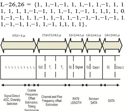
The IEEE 802.11p PHY uses 64 subcarriers OFDM that includes 48 data subcarriers and 4 pilot subcarriers. The 4 pilot signals are used for tracing the frequency offset and phase noise, and a relocated on subcarrier −21, −7,7 and 21. The short training symbols placed at the first part of every data packet (t1 through t10 shown in Figure 2.1), relates to the signal detection, time synchronization, and coarse frequency offset estimation. The long training symbols (T1 and T2), which are located after the short training symbols, are used for channel estimation. GI2 is used as guard interval for long training sequence and GI is used as guard interval for OFDM symbols. The cyclic prefix employed to reduce the ISI.
The total training length is 16 µs. A short OFDM training symbol consists of 12 subcarriers, which are given by
S−26,26 = p(13/6) {0, 0, 1+ j, 0, 0, 0,−1 − j, channel Estimation accuracy, long OFDM training symbols are used. the long training
Figure 1: OFDM training structure.
where the modulation is given by the element’s value. Depending on the data rates, different modulation schemes and coding rates must be applied. Table1.1 illustrates the difference between IEEE 802.11p and IEEE802.11a standard.
Table 1 Comparisons view on the key parameters of IEEE 802.11p PHY and IEEE
37 to the desired data rate had been used in
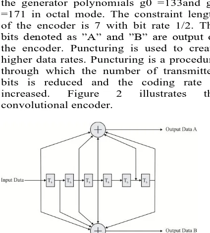
802.11p. The Convolutional encoder uses the generator polynomials g0 =133and g1 =171 in octal mode. The constraint length of the encoder is 7 with bit rate 1/2. The bits denoted as ‖A‖ and ‖B‖ are output of the encoder. Puncturing is used to create higher data rates. Puncturing is a procedure through which the number of transmitted bits is reduced and the coding rate is increased. Figure 2 illustrates the convolutional encoder.
Figure 2: Convolutional encoder (k=7). The minimum free distance of the code determines the performance of the convolutional code. dfree is the minimum Hamming distance between two different code words which is also called free distance.
2.1 Frame types:
There are three main types of frames:
1. Data frames: Used for data transmission. 2. Control Frames: To address some wireless
communication phenomena and control medium access of nodes in order to reduce collisions.
3. Management Frames: Are used to exchange management information, but they do not belong to the upper layers.
2.2 IEEE 802.11p Physical Layer Model:
The IEEE 802.11p Model represents a base band model for the physical layer in a Wireless Local Area Network (WLAN) in this physical layer model having three main parts transmitter, channel, and receiver each of this section is explaining below.
2.2.1 Transmitter Side:
Binary data is created according to a predefined mode. This mode is created In adaptive modulation control according to the SNR estimation at the receiver. This mode has to be entered to the data source to create the binary data. In The subsystem of data source a buffer exists whose output is according
to the Maximum bits per block which are chosen in the simulation parameter list.
IEEE 802.11p OFDM PHY includes different data rates which are selected according to the output of adaptive modulation. The system uses different modulation schemes due to different data rates. Figure 3 illustrates the subsystem of modulator. The modulator is sub divided as following:
Padding
Convolutional encoder
Puncturing convolutional codes
Matrix interleaver
General block interleaver
Rectangular QAM
Figure 3: Subsystem of modulator.
The Padding block changes the dimension of input matrix along its columns, rows or both of them according to the specified values. In this system each row is equal To one subcarrier, it means, rows are in the frequency domain and columns are in The time domain. In IEEE 802.11p base band model the padding is employed for truncating the input signal along column size. The specified output dimension is the number of bits per block that is different according to the different data rate and corresponding different code rate and modulation scheme.
The convolutional encoder is carried out for coding of the transmitted bits. Convolution codes have three main parameters, the number of input bits, k, number of output bits, n, and the number of memory register, m. k.(m + 1) is introduced as constraint length to define a convolutional encoder in Matlab Simulink. A poly2trellis function is used to convert generator polynomials to Trellis structure, see.
Trellis = poly2trellis (Constraint Length, Code Generator)
In this system the Trellis structure is poly2trellis (7, [171 133]).
38 can be used. The third and sixth element from the input vector is removed according to the puncture vector. Therefore the bit rate resulting from puncture vector is 3/2, finally bit rate will be 3/4 = 3/2.1/2, Matrix Interleaver and General Block Inter leaving can be employed in digital data transmission technologies to mitigate the effect of burst errors. When too many errors exist in one code word, due to a burst error, the decoding of a code word cannot be done correctly. To reduce the effect of burst error, the bits in one code word are interleaved before being transmitted. When interleaving occurs the place of bits will change, which means that a burst error cannot disturb a huge part of one code word.
In this SIMULINK model is defined by two steps. The first step is mapping of the adjacent coded bits in to the nonadjacent sub carriers that is implemented with the matrix interleaver. The second step is mapping the adjacent coded bits alternately onto significant bits of the constellation that is implemented with the general block interleaver.
Matrix interleaver interleaves the input vector according to the specified row and column. In this system the number of rows and columns is given by:
Interleaver Rows=16 Interleaver Columns = Number of transmitted bits per Four different modulation types are implemented:
BPSK
Each OFDM symbol in IEEE 802.11p has four pilot subcarriers. The pilot signals are used for tracing frequency offset and phase noise. The
location of pilot subcarriers is -21,-7, 7 and 21. The Pseudorandom Noise (PN) sequence generator block is carried out creating the pilot
Samples per frame = OFDM symbol per frame Preamble insertion is used for channel estimation in our model in order to improve the channel estimation accuracy. Four long OFDM training symbols are used instead of two long training symbol in this system. The long training symbols consist of 53 subcarriers that have a zero value at DC subcarrier.
The Pad block extends the input vector along its columns. The padding values are equal to zero, inserted at the end of the columns, where the specified dimension of the output is the number of points of the IFFT block cyclic prefix is used as a guard interval to mitigate the effect of ISI due to the multipath propagation. A selector block is applied as a cyclic prefix inserter to insert the last 16 subcarriers into the beginning of the OFDM symbols.
The multiplex block is the last block in the transmitter part to convert the signal from parallel to serial and to transmit time-domain samples of one symbol.
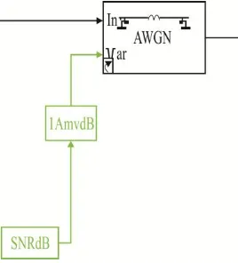
2.2.3 Radio Channel:
For the simulation a simple Additive White Gaussian Noise (AWGN) channel model is used, following by simulations with multipath Rayleigh fading together with AWGN model. variance of the noise, as shown in Figure 5,
39
2.2.4 Rayleigh Fading Channel with AWGN:
The multipath Rayleigh fading is added to an AWGN channel. Since a transmitted signal propagates along several paths in multipath channel to reach to the receiver, it may lead to different time delays. In the block, two parameter dialogs are specified, the delay vector is used to specify time delay for each path and the gain vector is used to specify the gain for each path at each delay. The number of paths is according to the length of the delay vector and the gain vector which must have the same length.
Figure 5: Multipath Rayleigh fading channel.
2.2.5 Receiver Side:
To convert a signal from serial to parallel, a de multiplex block is used. A reshaping block is a subsystem of this block and is employed to produce a matrix out of the input vector.
In the receiver the inserted cyclic prefix must be removed, to obtain the original input data. A selector block is used to remove the 16 subcarriers that are inserted into the beginning of the OFDM symbols.
In this part the data subcarriers are separated from pilot subcarriers and the n Parallel data symbols are converted to the N serial data symbols, to achieve the original signal.
Figure 6: Disassemble OFDM frame.
The demodulator subsystem performs the inverse tasks of the modulator subsystem. Figure 8 illustrates the subsystem of demodulator bank. Zero insertion.
Figure 7: Subsystem of demodulator bank.
3. Simulation Results:
In this below graphs show that IEEE 802.11p physical layer SNR (db), Bit rate (Mb/s) BER (per packet)
SNR(db)
Bit rate(Mb/s)
BER(per packet)
40
REFERENCES:
[1] IEEE Std 802.11, ―IEEE Standard for Information Technology-Telecommunications and Information Exchange Between Systems-Local and Metropolitan Area Networks-Specific Requirements — Part 11: Wireless LAN Medium Access Control (MAC) and Physical Layer (PHY) Specifications,‖ 2007.
[2] Y. Zang, L. Stibor, G. Orfanos, S. Guo, and H. Reumerman, ―An error model for inter vehicle communications in highway scenarios at5.9GHz,‖in International Workshop on Modeling Analysis and Simulation of Wireless and Mobile Systems, Montreal, Quebec, Canada, 2005.
[3] D V S Ramanjaneyulu, Gerardine Immaculate
Mary Vehicle-to-Vehicle Wireless Real Time Image Transmission for Traffic Awareness in International Journal of Applied Information Systems (IJAIS) – ISSN: 2249-0868 Foundation of Computer Science, FCS, New York, USA Volume 2– No.1, January 2012
[4] Roberto A. Uzcátegui, Universidad Nacional Experimental Politécnica ―Antonio José de Sucre‖ Guillermo Acosta-Marum, Georgia Institute of Technology ―WAVE: A Tutorial‖ TOPICSIN AUTOMOTIVE NETWORKING
[5] Arijit Khan, Shatrugna Sadhu, and Muralikrishna Yeleswarapu Dept. of Computer Science, University of California, Santa Barbara ―A comparative analysis of DSRC and 802.11 over Vehicular Ad hoc Networks‖ May 2009. [6] T. S. Rappaport, Wireless Communications:
Principle and Practice. NJ: Prentice-Hall, 1996. [7] E. Mark, Wireless OFDM Systems: How to
Make Them Work? Kluwer Academics Publishers, 2002.
[8] J. G. Proakis, Digital Communications. McGraw-Hill, 1995.