Volume 2008, Article ID 243548,14pages doi:10.1155/2008/243548
Research Article
Nonparametric Interference Suppression Using Cyclic Wiener
Filtering: Pulse Shape Design and Performance Evaluation
Anass Benjebbour, Takahiro Asai, and Hitoshi Yoshino
Research Laboratories, NTT DoCoMo, Inc., 3-5 Hikarinooka, Yokosuka, Kanagawa 239-8536, Japan
Correspondence should be addressed to Anass Benjebbour,[email protected]
Received 29 June 2007; Accepted 23 October 2007
Recommended by Ivan Cosovic
In the future, there will be a growing need for more flexible but efficient utilization of radio resources. Increased flexibility in radio transmission, however, yields a higher likelihood of interference owing to limited coordination among users. In this paper, we address the problem of flexible spectrum sharing where a wideband single carrier modulated signal is spectrally overlapped by unknown narrowband interference (NBI) and where a cyclic Wiener filter is utilized for nonparametric NBI suppression at the receiver. The pulse shape design for the wideband signal is investigated to improve the NBI suppression capability of cyclic Wiener filtering. Specifically, two pulse shaping schemes, which outperform existing raised cosine pulse shaping schemes even for the same amount of excess bandwidth, are proposed. Based on computer simulation, the interference suppression capability of cyclic Wiener filtering is evaluated for both the proposed and existing pulse shaping schemes under several interference conditions and over both AWGN and Rayleigh fading channels.
Copyright © 2008 Anass Benjebbour et al. This is an open access article distributed under the Creative Commons Attribution License, which permits unrestricted use, distribution, and reproduction in any medium, provided the original work is properly cited.
1. INTRODUCTION
In future wireless systems, there is a need to support the ex-plosive growth in number of users, be they persons or ma-chines, and the ever-increasing diversity in wireless applica-tions and user requirements. Nevertheless, one of the most challenging issues is the need to maximize the utilization of scarce radio resources. In recent years, as a solution towards a more efficient, yet flexible usage of spectrum resources, opportunistic overlay sharing of underutilized, already as-signed spectrum has been under consideration [1,2]. De-sign flexibility in radio, however, entails several challenging technical problems because of the eventual interference ow-ing to limited coordination between multiple users of possi-bly heterogeneous transmission characteristics, for example, symbol rate, symbol timing, carrier frequency, and modu-lation scheme. Thus, with the aim of achieving a higher de-gree of flexibility in spectrum usage, the development of non-parametric interference suppression/avoidance techniques to deal with heterogeneous unknown in-band interference is regarded as a crucial issue. In previous studies, interference suppression/avoidance techniques for orthogonal frequency division multiplexing- (OFDM-) based systems were
investi-gated [3,4]. In this paper, a spectrum sharing scenario where a wideband single carrier modulated signal is jammed by un-known NBI is investigated and a cyclic Wiener (CW) filter is utilized to take advantage of the property of cyclostationarity for nonparametric NBI suppression.
shown to be effective in suppressing NBI in CDMA systems, where the cyclostationarity of the NBI is utilized after esti-mating its corresponding cycle frequencies. Nevertheless, in a flexible spectrum usage environment, with limited coordi-nation it is not always possible to rely on the cyclostationarity property of the NBI, for example, the case when the NBI does not exhibit sufficient cyclostationarity to be utilized. Other papers that perform blind source separation (BSS) based on cyclostationarity also include [17,18]. However, interference suppression in these papers utilizes spatial filtering by assum-ing multiple antennas at the receiver. In this paper, we focus mainly on the exploitation of the spectral structure owing to the cyclostationarity property of the wideband signal. The NBI is assumed stationary and the exploitation of the spatial structure by multiple antennas at the receiver is left as op-tional.
The interference suppression capability of a CW filter is proportional to the amount of cyclostationarity available. For a single carrier modulated signal, the amount of cyclo-stationarity is strongly related to the spectral structure of the signal, represented by the cyclic nature of its second-order statistics, which itself is related to the pulse shaping filter used for limiting its occupied spectrum. In the context of crosstalk suppression, a near-optimal solution for transmit pulse shaping is derived to maximize the usage of cyclosta-tionarity [19,20]. Unfortunately, this solution, besides be-ing computationally intensive, is impractical in our scenario as it is dependent on the channel impulse response of NBI and also the signal-to-noise ratio (SNR) value. On the other hand, other existing raised cosine pulse shaping schemes are designed to satisfy the Nyquist criterion of zero intersymbol interference (ISI) to reduce self-interference; however, they do not take the existence of external interference into con-sideration and they are widely used for excess bandwidths of less than 100%, that is, a roll-offfactor of less than 1.0. To improve the CW capability to suppress the external in-band interference, a larger amount of cyclostationarity needs to be induced by expanding the excess bandwidth of the existing pulse shaping schemes. For this purpose, raised cosine pulses derived for excess bandwidths beyond 100% can be utilized [21,22]. However, it is not clear to what extent the interfer-ence suppression capability of CW filtering can be enhanced using such pulse shaping.
1.1. Contributions
The objective of this work is to clarify the impact of pulse shaping design on the interference suppression capability of CW filtering. Specifically, we propose for a wideband signal, for both the cases of unknown and known carrier frequency offsets (CFOs), two new pulse shaping schemes that outper-form existing raised cosine pulse shaping schemes even for the same amount of excess bandwidth. Based on computer simulation, the performance of CW filtering is evaluated un-der several interference conditions and over both AWGN and Rayleigh fading channels. With regard to the impact of pulse shaping on the interference suppression capability of CW fil-tering, simulation results reveal that there is no advantage de-rived from increasing the excess bandwidth of existing pulse
shaping for the case of NBI with a large CFO, that is, NBI lying outside the Nyquist bandwidth of the wideband sig-nal. Also, the results show that for the case of NBI with a small unknown or known CFO, the proposed pulse shap-ing schemes, compared to existshap-ing pulse shapshap-ing schemes, yield (1) substantially improved quality of extraction for the wideband signal; and (2) less interference from the wideband signal-to-narrowband signal.
The remainder of this paper is structured as follows. Section 2 introduces the fundamentals of cyclostationarity and CW filtering. Section 3 presents the assumed signal model and basic receiver structure. InSection 4after a brief review of near-optimal and existing pulse shaping schemes, the concept of the proposed pulse shaping is explained and examples are described for both the cases of unknown and known CFO.Section 5presents extended receiver structures for the narrowband signal, frequency-selective channels, and multiple receive antennas. Simulation results are presented inSection 6. The paper concludes inSection 7with a sum-mary recapping the main advantages of the proposed pulse shaping schemes.
1.2. Notations
Lower-case bold, as in x, denotes vectors and ∗denotes a complex conjugation. TermErepresents the probabilistic ex-pectation,·denotes the average over time,⊗is the convo-lution operator, andδis Dirac’s delta function. Given a ma-trixA,AT represents its transpose,A†its Hermite conjugate,
andAits vector norm.
2. TECHNICAL BACKGROUND
In this section, we briefly review concepts that are related to cyclostationarity and are relevant to this paper.
2.1. Wide-sense cyclostationarity
Leta(t) be a complex-valued zero-mean signal. The signal,
a(t), is said to be wide-sense (second-order) cyclostationary or exhibit wide-sense cyclostationarity (WSCS) [5] with cy-cle frequency,γ /=0, if and only if the Fourier transform of its time dependent autocorrelation function,Raa(t+τ/2,t− τ/2)=E[a(t+τ/2)a∗(t−τ/2)], called the cyclic autocorre-lation function (CAF),
Rγaa(τ)=lim
I→∞
1
I I/2
−I/2Raa
t+τ 2,t−
τ
2
e−j2πγtdt, (1)
is not zero for some values of lag parameterτ. In (1), I is the observation time interval. On the other hand, the signal,
a(t), is said to exhibit conjugate WSCS with cycle frequency,
β /=0, if and only if the Fourier transform of its conjugate time dependent autocorrelation function, Raa∗(t+τ/2,t−
τ/2)=E[a(t+τ/2)a(t−τ/2)], called the conjugate CAF,
Rβaa∗(τ)=lim
I→∞
1
I I/2
−I/2Raa
∗
t+τ
2,t−
τ
2
e−j2πβtdt, (2)
Another essential way of characterizing WSCS and con-jugate WSCS stems from the cyclic nature of the power spec-trum density of a cyclostationary signal. This is represented by the Fourier transform of CAF, known as spectral correla-tion density (SCD) and is given by
Sγaa(f)=
is the complex envelope of the spectral component ofa(t) at frequencyνwith approximate bandwidth 1/T. Similarly,
Sβaa∗(f)=
Accordingly, the cycle frequencies,γ, correspond to the frequency shifts for which the spectral correlation expressed by (3) is nonzero. Similarly, the cycle frequencies,β, corre-spond to the frequency shifts for which the conjugate spectral correlation expressed by (5) is nonzero.
Also note that forγ = 0, the CAF, Rγaa, reduces to the classical autocorrelation function of a(t). For single carrier modulated signals, the cycle frequenciesγ are equal to the baud rate and harmonics thereof. Meanwhile, cycle frequen-ciesβare equal to twice the carrier frequency, possibly plus or minus the baud rate and harmonics thereof. Following this, conjugate cyclostationarity can be observed in carrier-modulated signals [6]. However, the conjugate CAF,Rβaa∗, re-duces to zero for single carrier modulated baseband signals when balanced modulation, for example, quadrature ampli-tude modulation (QAM), is used.
2.2. CW filtering
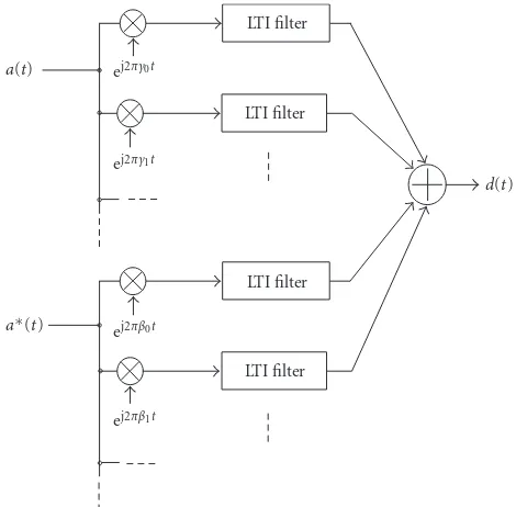
It is well known that optimum filters for extracting a signal from a stationary received signal are time-invariant and given by Wiener filters. Similarly, optimum filters for extracting a signal from a received signal that exhibits cyclostationarity with multiple cycle frequencies are multiply-periodic time-variant filters which are shown to be equivalent to frequency shift linear time-invariant filters and are known as CW filters [12]. The general input-output relation of the CW filter for a complex-valued input signal,a(t), is given by
d(t)= output signal. TermsRandSare the number of the cycle fre-quenciesγrandβs, respectively. According to (6), the CW fil-ter jointly filfil-ters the input signal and its conjugate to produce
LTI filter
Figure1: Illustration of the general input-output relation for a CW filter.
the output signal. This corresponds to a linear-conjugate-linear (LCL) filter which is optimum for complex-valued sig-nals [23]. Besides, according to (6), the CW filter implic-itly utilizes nonconjugate cyclostationarity and conjugate cy-clostationarity throughRnonconjugate linear time-invariant (LTI) filters of impulse-response,{wr(t)}, r =1,. . .,R, and S conjugate LTI filters of impulse response, {vs(t)}, s = 1,. . .,S, respectively.
Taking the Fourier transforms of both sides of (6), we obtain respectively, subjected to a number of frequency-shifting op-erations by amountγrandβs, then these are followed by LTI filtering operation with impulse response functions wr(·) and vs(·) and transfer functions Wr(·) and Vs(·). Subse-quently, a summing operation of the outputs of all LTI filters is performed. As a result, for a cyclostationary input signal,
a(t), the CW filter is equipped with the necessary operations to take advantage of the spectral structure ofa(t) owing to the nonzero correlation betweenA(f) andA∗(f −γ), and
A(f) andA(−f +β) (cf. (3) and (5)). An illustration of the general input-output relation of the CW filter is depicted in Figure 1.
3. DESCRIPTION OF ASSUMED SPECTRUM SHARING SCENARIO
Channel response
h1,c(t) Channel response
h2,c(t) AWGN
n(t)
y(t) +
ej2πΔf t Pulse shaping
h2,p(t)
Pulse shaping
h1,p(t) Narrowband signal
x2(l)δ(t−φ−lT2)
Wideband signal
x1(l)δ(t−lT1)
Figure2: Illustration of the baseband signal model of two spectrally overlapping asynchronous signals having different symbol rates and a
carrier frequency offset.
Adaptive filter
Adaptive filter
Adaptive filter Error signal
y(n) yγ0(n)
yγ1(n)
yγ−1(n)
ej2πγ−1n ej2πγ1n
y(t)
q/T1(q >1)
M
at
ched
filt
er
Cycle frequencies for wideband signal
γ−1=1/T1,γ0=0,γ1= −1/T1 −
1/T1 d1(l)
t(n) Recovered wideband signal
Reference wideband signal
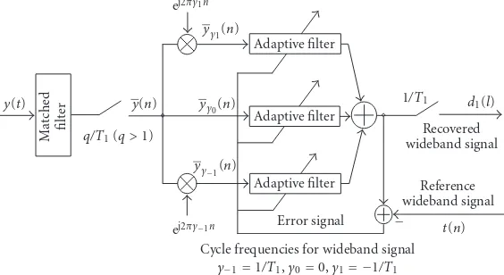
Figure3: The receiver structure CW1: a matched filter followed by a CW filter that extracts the wideband signal by exploiting the cyclosta-tionarity of the wideband signal.
the basic structure for the receiver used are described in the following.
3.1. Signal model
The assumed signal model consists of one wideband single-carrier modulated signal, one narrowband signal and noise. The complex envelope of the received baseband signal,y(t), is given by
y(t)= l
x1(l)δt−lT1 ⊗h1,p(t)⊗h1,c(t)
+
l
x2(l)δt−lT2−φ ⊗h2,p(t)⊗h2,c(t)
×ej2πΔf t+n(t).
(8)
At the right side of (8), the first term corresponds to the wideband signal with a baud rate of 1/T1, the second term corresponds to the narrowband signal with a baud rate of 1/T2 < 1/T1, and the last term, n(t), represents complex white circular Gaussian noise. TermsΔf andφare the car-rier frequency offset and the symbol timing offset between the wideband and narrowband signals, respectively. In addi-tion,h1,p(t),h2,p(t) andh1,c(t),h2,c(t) are the time response of the transmit pulse shaping filters and the channel impulse
responses for the wideband and narrowband signals, respec-tively. The transmitted symbols for the wideband and nar-rowband signals, x1(l) and x2(l), are modulated using bal-anced QAM.
In the signal model above, we assume that only the wide-band signal is cyclostationary, that the narrowwide-band signal is stationary, that its parameters are basically unknown to the wideband signal, and that a CW filter is utilized at the re-ceiver for non-parametric suppression of NBI. Then to im-prove the quality of extraction of the wideband signal using the CW filter described in the previous section, the design of the pulse shaping filter,h1,p, is studied. In the next section, we first present in detail the basic structure that is assumed for the CW receiver.
3.2. Basic receiver structure
each branch corresponds to one cycle frequency,γ ∈ A = {−1/T1, 0, 1/T1}, for the wideband signal. Let us denote the target signal ast(n) and the oversampled received signal as
y(n) = y(n/Ts), whereTs = q/T1(q > 1) is the sampling rate. This receiver is denoted as CW1. The receiver, CW1,
jointly adjusts the coefficients,Wγ, of the LTI filters corre-sponding to nonconjugate branches such that the TA-MSE between the summation of the outputs of the LTI filters and the target signal,t(n), is minimized as follows:
W=arg min
where the LTI filters corresponding to all cycle frequencies,
γ ∈ A, are fractionally spaced filters of finite impulse re-sponse (FIR) of orderL.
4. PULSE SHAPE DESIGN
Before transmission a signal is traditionally pulse shaped to limit its occupied bandwidth while still satisfying the Nyquist criterion of zero ISI to reduce self-interference [24]. One of the basic pulses used is the sinc pulse which occupies a minimal amount of bandwidth equal to the Nyquist (i.e., information) bandwidth. The Nyquist bandwidth is given by [−1/2T1, 1/2T1] for the wideband signal with a sym-bol rate of 1/T1. However, sinc pulses are noncausal and susceptible to timing jitter; thus, other pulses that occupy more bandwidth than the Nyquist bandwidth are usually employed in practice. The difference between the occupied bandwidth and the Nyquist bandwidth, normalized by the Nyquist bandwidth, is known as the excess bandwidth and measured in percentage. For example, a pulse that occu-pies twice the Nyquist bandwidth has an excess bandwidth of 100%. Although existing pulse shaping schemes are de-signed to satisfy the Nyquist criterion of zero ISI, they do not take into account the immunity of the pulse-shaped signal against in-band interference. The optimal pulse shaping that takes advantage of the spectral structure owing to cyclosta-tionarity to suppress in-band interference corresponds to the search for a solution to the joint optimization problem for minimizing the following TA-MSE:
min
whereh1,pis the impulse response of the transmit pulse shap-ing filter for the wideband signal andWis the impulse re-sponse of the CW filter at the receiver. The problem of ob-taining in closed-form the solution to the above joint opti-mization is open. One heuristic method to this problem is to
find a near-optimal solution through an iterative alternating search process between the optimalh1,p for a fixedW and the optimalWfor a fixedh1,p[19,20]. Nevertheless, this so-lution involves intensive computation due to large matrix in-version at every iteration until convergence. In addition, and more importantly, this solution turns out to be dependent of the channel impulse response of the NBI and the SNR value, which is not practical for our spectrum sharing scenario with unknown NBI.
4.1. Existing raised cosine pulse shaping
Another possible heuristic solution to the joint optimization problem that requires less complexity consists of minimizing (11) through solely optimizingW. Thus,h1,pis fixed. Then, for the purpose of obtaining a reduced TA-MSE, a higher amount of cyclostationarity is induced toh1,p by extending its excess bandwidth while still keeping the zero ISI crite-rion satisfied. Raised cosine pulses, however, are typically ob-tained for an excess bandwidth up to 100% (i.e., roll-off fac-tor,α, less than 1.0). For excess bandwidths beyond 100%, raised cosine pulses derived in [21,22] can be deployed. In the following, we describe the frequency responses of exist-ing raised cosine pulses for excess bandwidths less than and beyond 100%:
(i) raised cosine pulses with excess bandwidth less than 100%: of the pulse shaping filter, factorαcontrols the amount of excess bandwidth;
−1/T1 −0.5/T1 0Δf 0.5/T1 1/T1
f P
B A
Wideband signal Narrowband signal
SQRC20
(a) Excess bandwidth=20%
−1/T1 −0.5/T1 0Δf 0.5/T1 1/T1
f P
B A
D C
Correlated parts of spectrum: (A & D), (B & C) SQRC120
Wideband signal Narrowband signal
(b) Excess bandwidth=120%
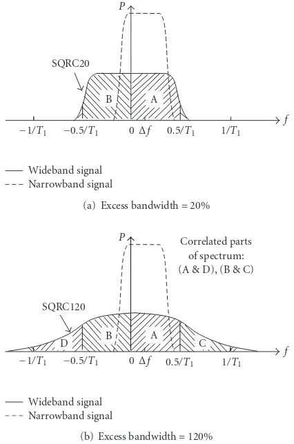
Figure4: Examples of existing raised cosine pulse shaping schemes.
The square root version of existing raised cosine pulses, denoted as SQRC, is given by H(f) and illustrated in Figure 4when the excess bandwidth is 20% and 120%.
From the perspective of nonparametric interference sup-pression using cyclostationarity, one main drawback of the aforementioned existing pulse shaping schemes remains in the manner by which the power is distributed over their frequency response. In fact, most of the power is concen-trated around the center carrier frequency within the Nyquist bandwidth, which results in the frequency components out-side the Nyquist bandwidth having relatively low power (cf. Figure 4). As will be clarified later in the simulation results, this incurs a very limited interference suppression capability for the CW filter against interference lying within the Nyquist bandwidth of the wideband signal.
4.2. Proposed pulse shaping
For the aforementioned existing pulse shaping schemes, al-though the excess bandwidth can be increased, this might not always be efficient as it is for the case of interference lying within the Nyquist bandwidth of the wideband signal. Our concern, therefore, is to improve the interference suppression capability of CW filtering while making use of pulse shap-ing with the minimal amount of excess bandwidth. Here, in-spired by ideas from both near-optimal and existing pulse
shaping schemes, we propose a design for pulse shaping,h1,p, based on the following two criteria:
(1) reduce self-interference owing to ISI;
(2) improve suppression capability against external inter-ference lying within the Nyquist bandwidth of the wideband signal.
Keeping the above two criteria in mind, two pulse shaping schemes are proposed for both the cases of unknown and known CFOs.
4.2.1. Unknown CFO case
For this case, it is not possible to avoid NBI; therefore, the immunity of the wideband signal against NBI must be in-creased irrespective of the CFO. For this purpose, it is im-portant to design a pulse shaping filter that has a frequency response in which the power is distributed almost uniformly over all the frequency components. As a solution, we pro-pose a time-domain shrunk raised cosine (TSRC) pulse shap-ing for an excess bandwidth beyond 100%. The frequency response of TSRC pulses is obtained by shrinking the time response, equivalently stretching the frequency response, of the existing raised cosine pulses for excess bandwidth less than 100%. To construct such a pulse for an excess band-widthα×100% withm+ 1> α ≥m≥1 (mis a nonzero positive integer), we substitute in (12)αby (α−m)/(m+ 1) and f by f /(m+ 1). Based on this, the frequency response of a time-domain 1/(m+ 1) shrunk raised cosine pulse with excess bandwidthα×100% withm+ 1> α≥mis given by
Hα,m(f)= ⎧ ⎪ ⎪ ⎪ ⎪ ⎪ ⎪ ⎪ ⎪ ⎪ ⎨ ⎪ ⎪ ⎪ ⎪ ⎪ ⎪ ⎪ ⎪ ⎪ ⎩
1, 0≤f ≤0.5(2m+ 1−α) T1 ,
A(f,m), 0.5(2m+1−α)
T1 ≤f≤
0.5(1+α)
T1 ,
0, 0.5(1 +α)
T1 ≤ f,
A(f,m)=0.5
1−sin
π
(α−m)
f T1−m+ 1
2
,
(14)
whereHα,m(−f)=Hα,m(f). In the following, the square root version of these pulses is called time-domain shrunk square root raised cosine, denoted as TSSQRC, and their frequency response is given by Hα,m(f). Form = 1, the obtained square root pulses are called time-domain half shrunk square root raised cosine (HSSQRC) pulses. The proposed HSSQRC pulse shaping is illustrated in Figure 5for an excess band-width of 120%.
−1/T1 −0.5/T1 0Δf 0.5/T1 1/T1
Figure5: An example of proposed pulse shaping for the case of unknown carrier frequency offset.
−1/T1 −0.5/T1 0 0.5/T1 1/T1
Figure 6: Examples of proposed pulse shaping for the case of known carrier frequency offset.
against interference lying within the Nyquist bandwidth can be expected to increase compared to existing pulse shaping schemes.
4.2.2. Known CFO case
For this case, the knowledge of the CFO can be utilized to minimize interference from the narrowband signal to the wideband signal and concentrate the transmit power of the
wideband signal on spectrum parts that are noncorrupted by the narrowband signal. To make this possible, after increas-ing the excess bandwidth as in TSRC pulse shapincreas-ing, we null out (notch) the part of the spectrum inside which the nar-rowband signal falls. Such a pulse shaping is called notched TSRC (NTSRC).
In the following, we assume that the narrowband signal occupies a bandwidth less than one Nyquist zone (<1/T1) of the wideband signal. This is reasonable because 1/T2<1/T1. One smooth construction of NTSRC pulse shaping is ob-tained byHα,α,Δf,m(f) = Hα,m(f)−Hα,0(f −Δf), where one Nyquist zone of the frequency response of the TSRC pulse shaping is nulled out by subtracting the frequency response of a raised cosine pulse having center frequency Δf, a Nyquist bandwidth, 1/T1, and an excess bandwidth of
α×100%, whereα<1. ForΔf =0, the frequency response of NTSRC pulse shaping is given by
Hα,α,0,m(f) the square root version of these pulses is called notched time-domain shrunk square root raised cosine, denoted as NTSSQRC, and their frequency response is given by
Hα,α,Δf,m(f). Form =1, the obtained square root pulses are called notched time-domain half shrunk square root raised cosine (NHSSQRC) pulses. The proposed NHSSQRC pulse shaping is illustrated in Figure 6for an excess band-width of 120%.
Regarding the first criterion, it is easy to verify that the NTSRC pulse shaping described by (15) does not satisfy the Nyquist criterion of zero ISI. Nevertheless, owing to the properly induced cyclostationarity prior to spectral notch-ing, ISI compensation is feasible by using the CW filter at the receiver. Regarding the second criterion, besides the benefits of the TSRC pulse shaping, for NTSRC pulse shaping, thanks to spectral notching, efficient power allocation is possible as the signal power is not wasted on corrupted spectrum.
5. EXTENDED RECEIVER STRUCTURES
5.1. Receiver for narrowband signal
coordination levels between the narrowband and wideband signals: (1) unknown and known CFOs; and (2) unknown and known cycle frequencies of the wideband signal.
(i) The case of an unknown CFO: for this case, TSSQRC is utilized for the wideband signal as proposed. For the receiver of the narrowband signal, we consider the two cases below.
(a)The case where the cycle frequencies of the wide-band signal are unknown to the receiver of the nar-rowband signal. For this case, the narrowband signal has no information on the characteristics of the wideband signal, and the in-band inter-ference caused by the wideband signal cannot be removed from the narrowband signal. Sig-nal extraction can only be carried out using the matched filter for the narrowband signal, here-after denoted as MF2.
(b)The case where the cycle frequencies of the wide-band signal are known to the receiver of the nar-rowband signal.For this case, the cycle frequen-cies of the wideband signal are known to the receiver of the narrowband signal. Having this knowledge, the receiver structure, CW2,
illus-trated inFigure 7can be deployed. The receiver, CW2, for the narrowband signal is intentionally
not equipped with a matched filter to allow for large bandwidth reception that also includes the wideband signal. Its CW filter part utilizes the cy-cle frequencies of the wideband signal so that the spectral structure for the wideband signal is uti-lized to remove from the narrowband signal the interference owing to the wideband signal.
(ii) The case of a known CFO: for this case, since NTSSQRC is utilized, the interference from the wide-band signal to the narrowwide-band signal is minimal. Therefore, the extraction of the narrowband signal can be carried out by simply using the matched filter, MF2.
5.2. Receiver for frequency-selective channels
Over frequency-selective channels, multipath delay yields ad-ditional channel ISI. For both proposed and existing pulse shaping schemes, channel ISI causes frequency selectivity of the channel that destroys the spectral structure owing to the cyclostationarity induced by the transmit pulse shaping fil-ter of the wideband signal. Therefore, channel ISI results in reducing the NBI suppression capability of the CW receiver. In order to restore the destroyed spectral structure, the CW filter needs to be combined with an equalization scheme to cope with channel ISI. Here, we combine the CW filter with a decision feedback (DF) filter. This combined receiver is de-noted as CW1/DF and its structure is depicted inFigure 8.
It is noteworthy that the merit of the receiver, CW1/DF, is
that nonparametric interference suppression and channel ISI equalization can be performed jointly with no information on the NBI. In the receiver, CW1/DF, the filter weights for
the feedforward part consisting of the CW1receiver and the
Adaptive filter
Adaptive filter
Adaptive filter
Cycle frequencies for wideband signal =1/T1, 0,−1/T1
Figure7: The receiver structure CW2: A CW filter that extracts the narrowband signal by taking advantage of the cyclostationarity of the wideband signal.
filter weights for the feedback part are computed jointly by minimizing the TA-MSE of (16)
W=arg min the feedforward CW and the decision feedback filters. Here, the decision statistic vector,d1, is given by
d1(l)=" d1
where the feedback filter is a baud-spaced FIR filter of order
Lb.
5.3. Receiver with multiple antennas
When multiple antennas are employed at the receiver, both the spectral and spatial structures of the received signal can be utilized to extract the target signal. This can be achieved by cycle frequency shifting the signals received at all antennas. Thus, the number of branches, that is, LTI filters, for a re-ceiver withNantennas becomesNtimes the case of a receiver with one single antenna. This receiver is denoted as CW1,N (N >1). The optimization of the weights for all branches is jointly performed for CW1,N as follows:
min
M
at
ched
filt
er
Adaptive filter
Adaptive filter Adaptive filter
Adaptive filter
Cycle frequencies for wideband signal =1/T1, 0,−1/T1
−
− 1/T1
d1(l)
y(t)
e−j(2πn/T1) ej(2πn/T1)
q/T1
Error signal Feedforward filter
Feedback filter
y(n) Received
signal
Recovered wideband signal
Reference wideband signal
Figure8: The receiver structure CW1/DF: a CW1receiver combined with a decision feedback filter.
6. PERFORMANCE EVALUATIONS
6.1. Computer simulation setup
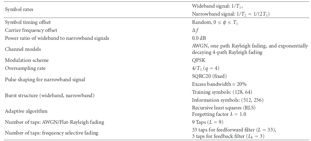
The bit-error rate (BER) performance of the wideband and narrowband signals is evaluated for the assumed spectrum sharing scenario. The channel models used are AWGN, a frequency-flat Rayleigh fading channel with one single path, and a frequency-selective Rayleigh fading channel with four baud-spaced paths, where the average power ratio between any two successive paths is −4.0 dB. The channel for each path is modeled as quasistatic Rayleigh fading, as we as-sumed that the channel stays invariant for the whole frame but changes from a frame to another. Basically, the number of antennasN at the receiver is one. IfNis more than one, this will be mentioned. Simulation parameters are depicted inTable 1. For the narrowband signal, we use a fixed SQRC pulse shaping with an excess bandwidth of 20% (SQRC20). For the wideband signal, proposed HSSQRC and NHSSQRC pulse shaping schemes are used and compared to existing SQRC pulse shaping schemes, in several channel environ-ments and interference conditions. Throughout all the sim-ulation results, the average received power is normalized to be equal for all proposed HSSQRC, NHSSQRC, and exist-ing SQRC pulse shapexist-ing schemes. Also, for NHSSQRC pulse shaping, the factorα(cf. (15)) is set to 0.2.
6.2. AWGN channel case
BER versusEb/N0for the wideband signal: W/o NBI
InFigure 9, without NBI, the receiver, CW1, shows almost
the same performance for both existing and proposed pulse shaping schemes regardless of the amount of excess band-width. This is because the average received power was nor-malized to be the same for all pulse shaping schemes.
BER versusEb/N0for the wideband signal:Δf =0.0
InFigure 10, with NBI andΔf = 0.0, the receiver, CW1, is
used to extract the wideband signal. The BER performance of the wideband signal is largely degraded for existing SQRC20 pulse shaping since it contains a limited amount of cyclo-stationarity. On the other hand, our proposed HSSQRC120
NHSSQRC120, CW1 HSSQRC120, CW1 SQRC120, CW1
SQRC20, CW1 10−5
10−4 10−3 10−2 10−1 100
A
ver
age
b
it
er
ro
r
rat
e
0 5 10 15 20
Eb/N0(dB)
Figure9: BER versusEb/N0for the wideband signal: AWGN chan-nel and w/o NBI.
pulse shaping yields much better BER performance than the existing SQRC120 pulse shaping scheme. This is because less noise enhancement occurs at the CW filter when the HSSQRC and NHSSQRC pulse shaping schemes are used, since the power of the frequency components of the wide-band signal separated by one cycle frequency (±1/T1) from its corrupted Nyquist bandwidth is higher with the HSSQRC and NHSSQRC pulses than with the existing SQRC pulses (cf. Figures4,5, and6).
Table1: Simulation parameters.
Symbol rates Wideband signal: 1/T1,
Narrowband signal: 1/T2=1/(2T1)
Symbol timing offset Random, 0≤φ≤T1
Carrier frequency offset Δf
Power ratio of wideband to narrowband signals 0.0 dB
Channel models AWGN, one path Rayleigh fading, and exponentially
decaying 4-path Rayleigh fading
Modulation scheme QPSK
Oversampling rate 4/T1(q=4)
Pulse shaping for narrowband signal SQRC20 (fixed)
Excess bandwidth=20%
Burst structure (wideband, narrowband) Training symbols: (128, 64) Information symbols: (512, 256)
Adaptive algorithm Recursive least squares (RLS)
Forgetting factorλ=1.0 Number of taps: AWGN/Flat-Rayleigh fading 9 Taps (L=9)
Number of taps: frequency selective fading 33 taps for feedforward filter (3 taps for feedback filter (L L=33), b=3)
W/o interference SQRC20, CW1 SQRC120, CW1
HSSQRC120, CW1 NHSSQRC120, CW1 10−5
10−4 10−3 10−2 10−1 100
A
ver
age
b
it
er
ro
r
rat
e
0 5 10 15 20
Eb/N0(dB)
Figure10: BER versusEb/N0for the wideband signal: AWGN chan-nel andΔf=0.0.
to noncorrupted spectrum parts of the wideband signal (cf. Figure 6).
BER versus EBW for the wideband signal: Δf =0.0andEb/N0=10.0 dB
In Figure 11, the receiver, CW1, shows better interference
suppression with proposed HSSQRC and NHSSQRC pulses
even for less excess bandwidth (EBW) compared to existing SQRC pulse shaping, for example, HSSQRC with the EBW of 120% versus SQRC with the EBW of 180%. This is because less noise enhancement occurs at the CW filter when pro-posed pulse shaping is used. On the other hand, an increase in the EBW to beyond 120% does not improve the BER per-formance for the proposed pulse shaping inFigure 11. This is because the amount of cyclostatinarity induced by the pro-posed pulse shaping for the EBW of almost 120% is already sufficient for suppressing one interferer. A further increase in the EBW simply results in occupying a larger bandwidth, leading to lower power concentration, which degrades the BER performance for the receiver. To exploit the increase in EBW to beyond 120%, the number of branches for receiver, CW1, can be increased to more than three; however, the use
of more branches comes at the price of more tap weights to estimate and a more complex receiver structure although the BER improvement should be limited with only one interferer.
BER versusΔf for the wideband signal:Eb/N0=10.0 dB
InFigure 12, for a relatively largeΔf, the receiver, CW1,
per-forms sufficiently well with SQRC pulses having a minimal amount of excess bandwidth (e.g., SQRC20). This is because for a relatively large Δf, the matched filter before the CW filter at the receiver, CW1, also has a minimal amount of
ex-cess bandwidth and consequently can help the CW filter in suppressing interference lying on or outside the boundaries of the bandwidth occupied by the wideband signal. On the other hand, for zero and a smallΔf, that is, interference lying within the Nyquist bandwidth of the wideband signal, the re-ceiver, CW1, exhibits better performance using the proposed
SQRC, EBW<100% CW1 HSSQRC, EBW>100% CW1 NHSSQRC, EBW>100% CW1 SQRC, EBW>100% CW1 10−5
10−4 10−3 10−2 10−1 100
A
ver
age
b
it
er
ro
r
rat
e
0 0.5 1 1.5 2
EBW (%)
Figure11: BER versus EBW for the wideband signal: AWGN chan-nel,Δf=0.0 andEb/N0=10.0 dB.
cyclostationarity for interference suppression with proposed HSSQRC and NHSSQRC pulse shaping compared with ex-isting SQRC pulse shaping. Another important feature is that the BER of the receiver, CW1, is kept almost the same
irre-spective ofΔf for the HSSQRC and NHSSQRC pulse shap-ing schemes. This is brought about by the almost-flat shape of their frequency response (cf. Figures5and6).
BER versusEb/N0for the narrowband signal:Δf =0.0
In Figure 13, the BER of the narrowband signal is plotted as a function ofEb/N0 forΔf = 0.0. For the narrowband signal, its matched filter, MF2, or the receiver, CW2, is used
as the receiver. For both receivers, HSSQRC and NHSSQRC pulse shaping schemes yield better performance than exist-ing SQRC pulse shapexist-ing scheme. When the cycle frequencies of the wideband signal are known to the receiver of the nar-rowband signal, the narnar-rowband signal can use the receiver, CW2, to take advantage of the spectral structure due to the
cyclostationarity of the wideband signal to remove its inter-ference from the narrowband signal. For this case as well, the BER performance of the narrowband signal can be improved by using HSSQRC pulse shaping rather than using SQRC pulse shaping. Moreover, when NHSSQRC pulse shaping is used for the wideband signal, the BER performance for the narrowband signal is significantly improved as it receives al-most no interference from the wideband signal.
SQRC20, CW1 SQRC120, CW1
HSSQRC120, CW1 NHSSQRC120, CW1 10−5
10−4 10−3 10−2 10−1 100
A
ver
age
b
it
er
ro
r
rat
e
0 0.2 0.4 0.6 0.8 1 1.2 1.4
Δf×T1
Figure12: BER versusΔffor the wideband signal: AWGN channel andEb/N0=10.0 dB.
6.3. Fading channel case
BER versusEb/N0for the wideband signal: frequency-flat channel, one or two receive antennas, andΔf =0.0
In Figures 14and15, for both the cases of one receive an-tenna (N=1) and two receive antennas (N=2), the average BER performance of receivers CW1 and CW1,2is improved
over the frequency-flat fading channel by using pulses with a larger excess bandwidth. Also, for the same excess bandwidth of 120%, the use of HSSQRC120 and NHSSQRC120 pulse shaping schemes results in performance improvement com-pared to that for SQRC120 pulse shaping. The performance improvement, however, is decreased asN increases. This is because the more spatial degrees of freedom we have for in-terference suppression, the lower is the noise enhancement effect at the receiver.
BER versusEb/N0for the wideband signal:
frequency-selective, one receive antenna and decision feedback equalization,P=4, andΔf =0.0
InFigure 16, the average BER versus the average Eb/N0 for the wideband signal is evaluated over the frequency-selective Rayleigh fading channel. The BER performance for the re-ceiver, CW1, is largely degraded. This is because the receiver,
CW1, fails to equalize the multipath channel when this one is
nonminimum phase. Besides, in a frequency-selective chan-nel the receiver, CW1, needs to equalize jointly the multipath
HSSQRC120, CW2 NHSSQRC120, MF2 SQRC120, CW2 SQRC20, CW2
HSSQRC120, MF2 SQRC120, MF2 SQRC20, MF2 W/o interference 10−5
10−4 10−3 10−2 10−1 100
A
ver
age
b
it
er
ro
r
rat
e
0 5 10 15 20
Eb/N0(dB)
Figure13: BER versusEb/N0for the narrowband signal: AWGN channel andΔf=0.0.
W/o interference SQRC20, CW1 SQRC120, CW1
HSSQRC120, CW1 NHSSQRC120, CW1 10−3
10−2 10−1 100
A
ver
age
b
it
er
ro
r
rat
e
0 5 10 15 20
AverageEb/N0(dB)
Figure14: BER versusEb/N0for the wideband signal: frequency-flat fading channel, one receive antenna andΔf=0.0.
W/o interference SQRC20, CW1,2 SQRC120, CW1,2
HSSQRC120, CW1,2 NHSSQRC120, CW1,2 10−5
10−4 10−3 10−2 10−1 100
A
ver
age
b
it
er
ro
r
rat
e
0 5 10 15 20 25 30
AverageEb/N0(dB)
Figure15: BER versusEb/N0for the wideband signal: frequency-flat fading channel, two receive antennas (N=2) andΔf =0.0.
HSSQRC120, CW1 NHSSQRC120, CW1 SQRC20, CW1/DF SQRC20, CW1/DF
SQRC120, CW1/DF HSSQRC120, CW1/DF NHSSQRC120, CW1/DF W/o interference
With interference
10−3 10−2 10−1 100
A
ver
age
b
it
er
ro
r
rat
e
0 5 10 15 20
AverageEb/N0(dB)
we obtain a superior performance to that for receiver, CW1.
Also, a substantial performance improvement is obtained for using the proposed pulse shaping schemes than for using ex-isting pulse shaping schemes. Therefore, by using proposed pulse shaping schemes, the receiver, CW1/DF, effectively
per-forms joint nonparametric interference and ISI equalization over a frequency selective Rayleigh fading channel, which is disturbed by unknown NBI.
7. CONCLUSION
In this paper, we investigated a flexible spectrum sharing scenario where a wideband single-carrier modulated signal is jammed by unknown NBI. A CW filter is utilized to ex-ploit the cyclostationarity property of the wideband signal for nonparametric suppression of NBI. The impact of pulse shape design on the interference suppression capability of the CW filter is elucidated. For NBI with large CFO, that is, NBI lying outside the Nyquist bandwidth of the wide-band signal, we clarified that there is no advantage in mod-ifying the pulse shaping or increasing the excess bandwidth of the pulse shaping filter. For NBI lying within the Nyquist bandwidth of the wideband signal, we proposed new pulse shaping schemes for the wideband signal for both the cases of unknown and known CFOs between the wideband signal and NBI. Through extensive simulation results, we showed that the proposed pulse shaping schemes have the potential to substantially improve the interference suppression capa-bility of CW filtering over both AWGN and Rayleigh fading channels. A large part of the improvement achieved is due to the ability of proposed pulse shaping to take into consider-ation the existence of interference within the Nyquist band-width of the wideband signal by means of increasing their amount of cyclostationarity within a limited amount of ex-cess bandwidth while still minimizing self-interference by re-ducing ISI. The simulation results also revealed that the pro-posed pulse shaping performs well over frequency selective channels and for receivers with multiple receive antennas, and is also beneficial to the narrowband signal.
ACKNOWLEDGMENT
This paper was presented in part at the IEEE Vehicular Tech-nology Conference Fall and the IEEE International Sympo-sium on Personal, Indoor, and Mobile Radio Communica-tions, both in September 2006.
REFERENCES
[1] FCC 2003, “Facilitating opportunities for flexible, efficient, and reliable spectrum use employing cognitive radio technolo-gies,” FCC Document ET Docket, no. 03–108, December 2003. [2] S. Haykin, “Cognitive radio: brain-empowered wireless com-munications,”IEEE Journal on Selected Areas in Communica-tions, vol. 23, no. 2, pp. 201–220, 2005.
[3] T. Li, W. H. Mow, V. K. N. Lau, M. Siu, R. S. Cheng, and R. D. Murch, “Robust joint interference detection and decoding for OFDM-based cognitive radio systems with unknown in-terference,”IEEE Journal on Selected Areas in Communications, vol. 25, no. 3, pp. 566–575, 2007.
[4] S. Vogeler, L. Broetje, K.-D. Kammeyer, R. Rueckriem, and S. Fechtel, “Blind Bluetooth interference detection and suppres-sion for OFDM transmissuppres-sion in the ISM band,” inProceedings of the 37th Asilomar Conference on Signals, Systems and Com-puters (ACSSC ’03), vol. 1, pp. 703–707, Pacific Grove, Calif, USA, November 2003.
[5] W. A. Gardner, Ed.,Cyclostationarity in Communications and Signal Processing, IEEE Press, New York, NY, USA, 1994. [6] W. A. Gardner, “Cyclic Wiener filtering: theory and method,”
IEEE Transactions on Communications, vol. 41, no. 1, pp. 151– 163, 1993.
[7] E. Serpedin, F. Panduru, I. Sari, and G. B. Giannakis, “Bibliog-raphy on cyclostationarity,”Signal Processing, vol. 85, no. 12, pp. 2233–2303, 2005.
[8] D. T. M. Slock and C. B. Papadias, “Blind fractionally-spaced equalization based on cyclostationarity,” inProceedings of the 44th IEEE Vehicular Technology Conference (VTC ’94), vol. 2, pp. 1286–1290, Stockholm, Sweden, June 1994.
[9] A. Chevreuil and P. Loubaton, “Blind second-order identifica-tion of FIR channels: forced cyclostaidentifica-tionarity and structured subspace method,”IEEE Signal Processing Letters, vol. 4, no. 7, pp. 204–206, 1997.
[10] B. G. Agee, S. V. Schell, and W. A. Gardner, “Spectral self-coherence restoral: a new approach to blind adaptive signal ex-traction using antenna arrays,”Proceedings of the IEEE, vol. 78, no. 4, pp. 753–767, 1990.
[11] W. A. Gardner and W. A. Brown, “Frequency-shift filtering theory for adaptive co-channel interference removal,” in Pro-ceedings of the 23rd Asilomar Conference on Signals, Systems and Computers (ACSSC ’89), vol. 2, pp. 562–567, Pacific Grove, Calif, USA, November 1989.
[12] E. Ferrara Jr., “Frequency-domain implementation of peri-odically time-varying filters,”IEEE Transactions on Acoustics, Speech, and Signal Processing, vol. 33, no. 4, pp. 883–892, 1985. [13] G. Gelli, L. Paura, and A. M. Tulino, “Cyclostationarity-based filtering for narrowband interference suppression in direct-sequence spread-spectrum systems,”IEEE Journal on Selected Areas in Communications, vol. 16, no. 9, pp. 1747–1755, 1998. [14] G. Latouche, D. Pirez, and P. Vila, “MMSE cyclic equalization,” inProceedings of the IEEE Military Communications Conference (MILCOM ’98), vol. 1, pp. 150–154, Boston, Mass, USA, Oc-tober 1998.
[15] J. Zhang, K. M. Wong, Z. Q. Luo, and P. C. Ching, “Blind adap-tive FRESH filtering for signal extraction,”IEEE Transactions on Signal Processing, vol. 47, no. 5, pp. 1397–1402, 1999. [16] G. Gelli, L. Paura, and L. Verdoliva, “Adaptive interference
suppression in CDMA systems by LCL-PTV filtering,” in Pro-ceedings of the IEEE European Signal Processing Conference (EUSIPCO ’00), pp. 287–291, Tampere, Finland, September 2000.
[17] K. Abed-Meraim, Y. Xiang, J. H. Manton, and Y. Hua, “Blind source separation using second-order cyclostationary statis-tics,”IEEE Transactions on Signal Processing, vol. 49, no. 4, pp. 694–701, 2001.
[18] Y.-C. Liang, A. R. Leyman, and B.-H. Soong, “Blind source separation using second-order cyclic-statistics,” inProceedings of the 1st IEEE Signal Processing Workshop on Signal Processing Advances in Wireless Communications (SPAWC ’97), pp. 57–60, Paris, France, April 1997.
[20] M. L. Honig, P. Crespo, and K. Steiglitz, “Suppression of near-and far-end crosstalk by linear pre- near-and post-filtering,”IEEE Journal on Selected Areas in Communications, vol. 10, no. 3, pp. 614–629, 1992.
[21] L. F. Lind, S. G. Methley, and E. Deliot, “Raised cosine filters beyond 100% excess bandwidth,”Electronics Letters, vol. 31, no. 11, pp. 859–860, 1995.
[22] L. F. Lind, B.M. Al-Hashimi, and W. P. Somerset, “Linear pro-gramming design of FIR raised cosine filters with>100% ex-cess bandwidth,”Electronics Letters, vol. 32, no. 5, pp. 436–437, 1996.
[23] W. Brown and R. Crane, “Conjugate linear filtering,” IEEE Transactions on Information Theory, vol. 15, no. 4, pp. 462– 465, 1969.