R E S E A R C H
Open Access
Hand posture recognition using jointly optical
flow and dimensionality reduction
Nabil Boughnim, Julien Marot, Caroline Fossati and Salah Bourennane
*Abstract
Hand posture recognition is generally addressed by using eitherYCbCr(luminance and chrominance components) or HSV(hue, saturation, value) mappings which assume that a hand can be distinguished from the background from some colorfulness and luminance properties. This can hardly be used when a dark hand, or a hand of any color, is under study. In addition, existing recognition processes rely on descriptors or geometric shapes which can be reliable; this comes at the expense of an increased computational complexity. To cope with these drawbacks, this paper proposes a four-step method recognition technique consisting of (i) a pyramidal optical flow for the detection of large movements and hence determine the region of interest containing the expected hand, (ii) a preprocessing step to compute the hand contour while ensuring geometric and illumination invariance, (iii) an image scanning method providing a signature which characterizes non-star-shaped contours with a one-pixel precision, and (iv) a posture classification method where a sphericity criterion preselects a set of candidate postures, principal component analysis reduces the dimensionality of the data, and Mahalanobis distance is used as a criterion to identify the hand posture in any test image. The proposed technique has been assessed in terms of its performances including the computational complexity using both visual and statistical results.
Keywords: Hand posture; Contour signature; Classification algorithm; Optical flow; Principal component analysis
1 Introduction
Hand gesture and posture classification are of increasing interest for human-computer interaction. Previous works have concentrated on hand gesture classification (see [1,2] and references in [3,4]) where gesture command is based on slow movements with large amplitudes. Movements of the entire body were also investigated [5] for the purpose of action classification using of 3D representation and a 3D thinning algorithm. We believe that future applications should consider the classification of planar hand postures. This task is difficult because each finger must be distin-guished and, if a user wishes to afford a large dictionary of postures, some of them may be similar. The common approach for hand posture characterization is based on descriptors like Hu moments [6], Zernike moments [7], and Fourier descriptors [8,9]. The advantages of these methods relate to their intrinsic geometric invariance (i.e., translation, rotation, and scaling). However, the
*Correspondence: [email protected]
CNRS-UMR 7249 / Fresnel Institute - Ecole Centrale Marseille, Aix Marseille Université, D. U. de Saint-Jérôme, 13397 Marseille Cedex 20, France
results given in [10], and also presented in [3], show that Fourier descriptors do not take into account postures which are visually close. This is due to the low number of coefficients required to afford a moderate computational load: contours are smoothed and some details of the hand contours are skipped. Moreover, to the best of our knowl-edge, most hand posture recognition methods include a YCbCrmapping, which solely enhances hands with a color
which is close to the white color. Consequently, they fail to characterize hands of colored people, or hands wearing colored gloves.
In this paper we propose a hand posture recognition method which overcomes the main drawbacks of exist-ing methods [1,6,10]. Firstly, our method works indepen-dently of the hand color. To achieve this, we propose to adapt the optical flow for contour segmentation indepen-dently from its color where the hand contour is extracted from a color image. Secondly, we have improved the recognition performances especially for very similar pos-tures by proposing an approach for hand posture charac-terization, which involves an original signature developed in [3] and improved in [4]. Thirdly, we have been able to
keep the computational complexity including the memory requirements as low as possible. This has been possible by adapting a sphericity criterion to reduce the set of candi-date postures and by reducing the dimensionality of the data.
The remainder of the paper is organized as follows: in Section 2 we discuss the working conditions of the system before giving the problem statement and the objectives. In Section 3 we explain how optical flow is adapted as a hand contour detection method and how adequate preprocess-ing methods yield a binary image containpreprocess-ing only the hand contour. This allows the hand recognition process to be invariant to translation, scaling, and rotation. In Section 4 we provide details and interpretations of a proposed sig-nature for hand posture characterization which improves slightly our seminal work [3]. In Section 5 we present a distance criterion which allows us to classify hand pos-ture images; this distance criterion is associated with a sphericity criterion which is able to reduce the size of the dictionary of candidate postures. Also, a data dimen-sionality reduction algorithm is proposed to speed up the computation of this distance. In Section 6 we present a summary of the proposed method for hand posture recog-nition and a theoretical study of the computational load. The performances of the proposed algorithm are pre-sented in Section 7, as well as the comparative results. Finally we draw conclusions in the light of these results and state some prospects in Section 8.
2 Problem statement and image acquisition setup This section aims to state the problem of hand posture recognition and describes the dictionary of hand postures chosen in collaboration with an industrial partner. The practical setup dedicated to the acquisition of hand images is also discussed.
2.1 Problem statement
Systems which employ hand-driven human-machine interfaces (HMI) interpret hand gestures and postures in different modes of interaction depending on the applica-tion domain. Previous works have concentrated on hand gesture classification [1,2,10]. In [1,10], gesture command is based on slow movements with large amplitudes (see for instance in [1] the 12 types of hand gesture). In [2], local orientation histograms are computed. Very high recogni-tion rates are obtained but only in simplified condirecogni-tions (uniform background, limited alphabet) in order to facili-tate the hand region extraction.
To the best of our knowledge, applications should con-sider more complex operation conditions for the pur-pose of automated sign language decoding for instance, or touchless technology for retail applications as food and beverage vending machines. As such, the underlying image processing algorithms should face rather complex
environments. Moreover, hand gestures only are not suffi-cient to face the requirements of such applications. Unlike hand gestures, hand postures describe the hand shape and not its movement, and can be very different from each other. It is extremely difficult to recognize all possible con-figurations of the hand starting from its projection on a 2-D image. Indeed, some parts of the hand can be hidden. There exist some reference databases of specific hand postures, such as the Triesch database [11], available on the Web [12]. However, this database has a number of lim-itations: the number of images is low, the viewing angle and the size and the orientation of the hand are always the same, the images are in gray level and contain only the hand, and the background is rather simple. In this work we consider an application where our industrial part-ner wishes to have a rather elevated number of postures, which can yield later to various instructions for a HMI: this dictionary of postures is meant for automatic distrib-utors such as drink vending machines. For this reason, we have built our own database (also partially used in [3]). It contains 11 postures, which are displayed in Figure 1, with the corresponding posture index above. As will be shown in the results section, the background in these images is rather complex so that if our method works well with our database, it will certainly work with Triesch database.
These postures have been chosen to be easily performed by any person. They differ from the sign language which aims at easing lip reading. To afford a large dictionary, and thereby numerous functionalities of the human-machine interface, the dictionary must include a number of pos-tures which is large enough. This implies that similar postures may be present in the dictionary. Some postures permit to test the discrimination performances of the pro-posed and comparative methods: they are visually very close, such as postures 4 and 5, as well as postures 8 and 9. The images of the database were obtained as follows: an expert user shoots a movie containing the 11 postures. Then the frames of the video are split to get the images in the RGB color space. These images compound the learn-ing set. Other users which are not the expert user shoot a movie containing the 11 postures. The same process as for the learning database is adopted to get a set of images; these images compound the test set. To generate the learn-ing database and the test set, a simple setup involvlearn-ing a camera is used.
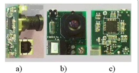
2.2 Hand image acquisition setup
1 2 3
4 5 6
7 8 9
10 11
Figure 1Postures of the database-cropped images.Each posture is placed below its corresponding index.
(90°) are used so that the field of vision is wide enough. The acquisition format can be either CIF or VGA. The video stream is transmitted to the computer by a USB con-nection in RGB format. The user can then interact with his computer and follow the evolution of his experiment directly on the screen.
The video stream is split into several frames, which are color images in RGB format. Each frame can then be processed, the first step being contour detection.
3 Detection and segmentation of the hand In this paper, the term contour detection denotes the fol-lowing operation: from an RGB frame provided by the camera, we aim at getting a binary image containing only the hand contour, as 1-valued pixels over a background of 0-valued pixels. This detection step is required for the next step, presented in a further section, which is contour characterization.
3.1 Overview of classical detection methods
A rule of thumb about contour characterization methods such as Fourier descriptors [10,13] is that they require a binary image I, possibly noise-free. The same con-straint holds in the frame of our work. To perform hand contour detection, some classical preprocessing meth-ods have been applied in previous works [3,4,10,13]: the
YCbCr mapping and the selection of theCr component
emphasize the hand surface with respect to the back-ground. Another mapping could also be used: in [14], HSV mapping is combined with a hue setting to distinguish the hand from other body parts. The results presented are convincing but this method exhibits a limitation: the usermustwear a red glove. To our knowledge, no study based on mappings from a color space to another such as YCbCr or HSV provides good detection results on
databases where the object of interest may exhibit any color. We want to develop a new method, which detects the hand independently of its color.
In [15], Soriano et al. propose a dynamic skin color model, for a segmentation purpose. Their method copes with changes in illumination. However, their method still relies on specific color properties of the skin. No result is presented concerning dark skins or hands wearing color gloves. In [16], Raja et al. modelled their object colors as a Gaussian mixture and estimated its parameters. In [17], Yoo et al. segment faces by computing a chromatic histogram, which exhibits the advantage of being insen-sitive to scaling and rotation. However, Yoo et al. must combine the chromatic histogram with the prior knowl-edge of the approximate shape of faces to detect them. We wish to perform hand posture recognition, so we can-not assume any prior knowledge about the shape of the hand. In other papers dealing with hand gesture recogni-tion, such as [18,19], good results are obtained on white hands but no result on black or colored hands is presented. The main drawback of the previously cited methods is that they do not handle the hands of colored people or those wearing colored gloves. More generally, as pointed out in [20], color has been widely used for hand seg-mentation and many approaches rely on predefined color models. However, it is difficult to predefine a color model in an application where there is no control over the back-ground, which may be of any color and complexity. It is also not sufficient if the color of an object on the back-ground is very similar to the color of the hand. We propose to adapt the concept of optical flow for the detection of hands through their movement.
3.2 Optical flow as hand detector
This work proposes, for the first time, to adapt optical flow as a contour detection solution. Indeed, the sign lan-guage or touchless technology applications to which our posture recognition method is dedicated assume that the hand user is, at least, slowly moving. This is also coherent with the current way to use touchless technology.
Optical flow was first introduced to characterize move-ments between two frames [21-23], without any prior knowledge about the contents of the frames by determin-ing the gray level values which have migrated from one point to another. The following sections are organized as follows: we firstly emphasize that the original work of [21] is based on a variational method upon which every variant of optical flow is still based and that some limitations were tackled by various successive modifications. Our choice is justified from a pyramidal version of optical flow [24]. Secondly, we focus on the applications of optical flow and we discuss the practical implementation of the proposed adaptation of optical flow with a view to propose a method to improve it.
The principles of optical flow are as follows: one can associate some kind of velocity with each pixel in the frame or, equivalently, some distance a pixel has covered
between the previous frame and the current one. Such a construction is usually referred to as a dense optical flow [21], which associates a velocity with every pixel in an image. Horn and Schunk, in [21], introduced a novel framework where the optical flow is computed as the solu-tion of a minimizasolu-tion problem. It is the first variasolu-tional method for optical flow estimation and variational meth-ods are still the predominant methmeth-ods to estimate dense optical flow. From the assumption that pixel intensities do not change over time, the optical flow constraint equation is derived. This equation relates the optical flow with the derivatives of the image.
In practical situations, calculating dense optical flow is not simple: Let us consider for instance the motion of a white sheet of paper. In this case many of the white pix-els in the previous frame will simply remain white in the next; only the edges may change, and even then only those perpendicular to the direction of motion. Hence the idea, developed originally in [22] of creating a sparse optical flow. This version of optical flow relies on some means of specifying beforehand the subset of points that are to be tracked. If these points have certain desirable properties, such as the ‘corners,’ then the tracking will be relatively robust and reliable.
In our acquisition environment, a hand may cross the whole acquired scene rather rapidly. This has lead us to consider adapting a pyramidal version [24] of Lucas-Kanade optical flow. This pyramidal version includes a multi-scale strategy which allows us to handle larger dis-placements while keeping the reduced computational load of Lucas-Kanade sparse method [22]. Moreover, in the past few years, optical flow has been widely improved to face harsh usage conditions, such as large displace-ments, by integrating rich descriptors [25] and to face discontinuities on motion boundaries [26].
In existing applications, optical flow is computed on the whole image in order to study its variations in brightness [21] or to provide a motion field [27].
The application which is the closest to our work is pre-sented in [25]: The visual results exhibit video sequences of moving persons. For each sequence, a flow image is computed to determine the velocity of the features. How-ever, as in previous works, the results obtained with optical flow are not interpreted in the sense that the move-ments of the persons in the scene are neither recognized nor labeled.
which surrounds the moving points detected by the opti-cal flow. In our application the hand is the moving object in the scene. We expect that extracting a region of interest around the hand accelerates and facilitates the process of posture recognition, in terms of invariance to scaling for instance.
One difficulty of our application relates to the selection of a relatively small number of points detected by the opti-cal flow. The norm of the corresponding flow vectors must fulfill the following conditions: it must be small enough to reject the unexpected vectors which are either due to variations in illumination; it must be high enough to reject the features which are slowly moving and which cannot be the hand. Another problem is how to get the 2-D gray level image required by optical flow from the RGB color image provided by the CMOS camera. In the general case, the mean value of the three R, G, and B channels is pro-vided as an input image to the optical flow component. In specific conditions where one knowsa priorithe color of the hand, for example wearing a glove, it is easy to modify slightly this step of the algorithm and work on one of the R, G, or B channels.
3.3 Preprocessing steps for hand segmentation
Let NOF be the number of moving points of interest, retrieved by the optical flow, from two frames: one obtained at timet, the other at timet>t. The coordinates of these points are denoted by(xo,yo), o= 1,. . .,NOF}.
Firstly, based on these points, we can select a region of interest (ROI) around the hand. As the shape of the hand is approximately elliptic, we choose an elliptic least-squares fitting [28]. The least-squares fitting meth-ods are sensitive to outliers, and we wish to ensure the robustness of the ROI selection to variations in illumina-tion. Therefore, we remove the moving points of interest which include an extreme (minimal or maximal) coordi-nate value. This may result in a possibly flawed detection by the optical flow. Let Ip denote an image contain-ing the remaincontain-ing movcontain-ing points. Based on the fittcontain-ing ellipse, we extract from the image a square ROI whose side length is 1.5 times the larger axis of the ellipse at timet.
Secondly, we segment the hand surface. We compute the center of mass of the moving points inIp; then, we deduce the hand pixel gray level distribution in each RGB band from the region next to the center of mass. Accord-ing to this distribution, we perform a histogram-based thresholding to each RGB band of the ROI as follows: for each band, the hand gray level distribution is com-puted around the center of mass. Let gl be the mean gray level value in this region. We compute a binary image where the pixels whose gray level values which are in the intervalgl−5 : gl+5are set to 1 while the others are set to 0. From these three binary images, we compute a
2-D binary image as the intersection of all 1-valued pixels of the thresholded R, G, and B bands. This binary image, denoted by ITh, contains the hand surface filled with 1-valued pixels and noise, that is, 1-valued pixels ran-domly distributed in the image.
Thirdly, we isolate the hand surface and refine its shape: we remove the outliers and fill out the holes in ITh. In practice, we select the largest set of connected pix-els, assuming that this object is the hand. Then, we remove the unexpected background pixels which are con-nected to the hand with mathematical morphology opera-tions, that is, erosions and dilations [1]. These operations remove the possibly remaining unexpected pixels from the background. This third preprocessing ensures that the whole algorithm is robust to variations in illumina-tion and to the inclusion of unexpected objects in the background.
Fourthly, we select once again an ROI: the smallest square subimage containing the whole hand. The number of rows (columns) of this image are the vertical (horizon-tal) Ferret diameters [29] of the hand. We obtain an image denoted byIfwhich contains only a filled hand.
Fifthly, we retrieve the hand contour, with a linear ‘Roberts’ filter. This yields an image Ic where the hand contour consists in 1-valued pixels, over a background of 0-valued pixels. This image will be used to compute a contour signature.
The preprocessing operations presented in this sub-section allows us to focus on an ROI and isolate the hand contour. This ensures invariance properties of the signature which will be presented in the next section.
4 Characterization of the hand: a further investigation on a signature for non-star-shaped contours
being skipped. Also, the more accurate the description, the smaller the regions, but the higher the computa-tional load and the storage requirements. Here, we pro-pose a contour signature which offers a resolution of 1 pixel.
The proposed scan is inspired not only from [32] but also from [34,35]. In [34] and [35], an image scan is pro-posed to characterize star-shaped contours. In a system of polar coordinates with adequately chosen poles, a con-tour is star-shaped if the radial coordinates (ρ) of its pixels are function of their angular coordinates (θ): for one θ
value there is only one ρ value ρ = f(θ ). In the gen-eral case, hand contours are not star-shaped since it is (nearly) impossible to find a pole for which the relation
ρ = f(θ )holds for all contour pixels. This has inspired us to investigate a characterization method which handles non-star-shaped contours.
The proposed method for contour characterization splits the image into several rings centered on a reference point. The requirements on the location of this reference point are low, unlike the condition imposed by the method in [35]. With this characterization method, we aim at dis-tinguishing very similar postures with a computational load which is lower than what the generally used Fourier descriptors would require.
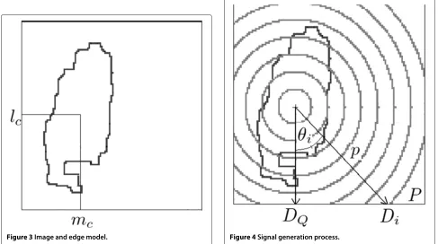
An image Ic, denoted by I, is assumed to have a size N×N, and its pixels are referred to, starting from the top left corner of the image, asIl,m(see Figure 3). The 1-valued
pixels constitute the expected contour where the contour pixels are located in a system of polar coordinates with
Figure 3Image and edge model.
pole{lc,mc}(see Figure 3). Unlike the methods proposed
in [35], where the center must be chosen in such a way that the contour is star-shaped, the computation of the center coordinates is not essential. For instance, this pole can be the center of mass obtained in the previous section. What we call signature in this paper is a set of data which char-acterize the corresponding contour. The signature that we investigate in this paper is based on the generation of signals out of an image. As in [35], a circular array of sensors is associated with the image. The sensor array is supposed to be placed along a circle centered on the pole
{lc,mc}. The number of sensors is denoted byQand one
sensor corresponds to one direction for the signal gener-ationDi, which makes an angleθi with the vertical axis.
See for instance theith and theQth sensors in Figure 4. The other sensors are not represented for the sake of clarity.
The method proposed in [35] is valid only for contours exhibiting at most 1 pixel for one directionDi. We wish
to overcome this limitation and characterize non-star-shaped contours, because the hand contours considered in this paper are mostly non-star-shaped. To separate the influence of each pixel located along a given directionDi,
we no longer generate one 1D signal, but a numberPof 1D signals on the antenna. Each signal corresponds to one ‘ring’ represented on Figure 4. We assume that for each directionDi, there is only 1 pixel in each of thePintervals.
BecauseI is square and of course not circular, Pdiffers
from one direction,Dito another. Its maximum
theoreti-cal value is, for instance,√N
2, iflc=N/2 andmc=N/2. In these conditions, the value ofQshould not exceed√2πN and it is sufficient to take into account all pixels of a given intervalp. Therefore, we generatePsignal vectors for each directionDi. For thepth interval (p = 1,. . .,P) and the
directionDi (i = 1,. . .,Q), the signal componentzp,i is
computed as follows:
zp,i=Ilp,i,mp,i
(lp,i−lc)2+(mp,i−mc)2 (1)
In Equation 1,lp,iandmp,iare the coordinates of the pixel
located in thepth interval and along theith directionDi; Ilp,i,mp,iis the pixel value, either 0 or 1, ofIat the location lp,i,mp,i, and we remind that{lc,mc}are the coordinates of
the pole from which the directionsDifor signal generation
start. The componentszp,iof the signature are equal to the
distance to the pole of the 1-valued pixels.
These componentszp,i(p= 1,. . .,P,i= 1,. . .,Q) can
be grouped into a matrixZof sizeP×Q:
Z=
⎡ ⎢ ⎢ ⎣
z1,1 z1,2 · · z1,Q z2,1 · · · ·
· · zp,i · · zP,1 · · · zP,Q
⎤ ⎥ ⎥
⎦ (2)
The first rows of matrixZcorrespond to the first inter-vals which are the nearest to the pole (see Figure 4). The values of the non-zero componentszp,iin these rows will
then be rather small. Conversely, the last rows of matrix
Zwill contain large values. One can notice also that for closed contours, any componentzp,Q of the last column
differs from the component of the same row and the first columnzp,1by at most 1 pixel.
All columns ofZshould have the same number of rows so that for the directions Di which cross less than P
intervals, 0-valued components are set inZfor the corre-sponding indicesi. If the width of the intervals is chosen such that there is at most 1 pixel per directionDiand per
interval, this matrix allows us to reconstruct exactly the contour; it contains the radial coordinates of the contour in the system of pole{lc,mc}. However, the purpose of the
signature is not necessarily to reconstruct exactly the con-tour; it should characterize a contour so that all postures can be distinguished. Also, the signature should be invari-ant to rotation. To achieve this, in previous works [3,4], we proposed to straighten up the image through several rotations, in order to maximize the hand Feret’s diame-ter in the horizontal direction. Instead, in this paper, we propose a technique which is much less computationally intensive where the componentszp,iof a given intervalp
are sorted. Consequently, all non-zero values of thepth row ofZ, where each corresponds to a contour pixel, are ordered and turned as the last components of thepth row. The proposed signature has invariant properties which are summarized follows:
• It is invariant to translation: for any position of the hand in the initial image, the box which encloses the contour is blindly estimated.
•It is invariant to scaling: whatever the size of the region of interest (small number of pixels if the camera is far from the hand, large number of pixels if the camera is near to the hand), the number of intervalsPfor the radial coordi-nate values, and the numberQof directions for signature generation is always the same. As a consequence, the size of matrixZwill be constant, whether the user’s hand is
near to or far from the camera. The signature depends on the shape of the hand, not on its size.
• It is invariant to rotation: for a given image, apply-ing a rotation leaves the number of non-zero pixels in the pth interval and their distances to the pole {lc,mc}
unchanged. Only the column index of the components zp,iin the signature is modified after rotation. After
sort-ing, the componentszp,ifor both images, before and after
rotation, are stored in the same columns of the signature. So, the sorting described above ensures the invariance to rotation.
•Sorting the components of each rowpof matrixZ per-mits to handle left hands as well as right hands. For a given posture, the user is allowed to use his left hand or his right hand, because the only difference observed in the signa-ture before sorting between the two cases resides in the column indices of the componentszp,i for a given rowp.
After sorting, the signatureZis the same for a right and for a left hand. This is an important progress with respect to previous works [3,4,10] because it relaxes the conditions of use of our method.
These invariance properties allow us to employ the pro-posed contour signature for hand posture classification purposes.
5 Classification of the hand posture
Let us consider H classes of hand postures. For the purpose of hand posture classification, Euclidean and Mahalanobis distances are used in [3,4]. In this paper we will focus on Mahalanobis distance and use the Euclidean distance as comparative method. We vectorize a matrixZ
characterizing a posture into aP.Qvector denoted byx. For each class h, a subset of hand photographs is avail-able. The H subsets constitute the learning set. This set was created by an expert who knows exactly what position his fingers should have to fit each posture in Figure 1. For a given classh, letMh be the number of images for this
class in the learning set. Letxnh, nh = 1,. . .,Mhbe the vectors ’x’ obtained from the images belonging to classh after computing the matrixZ. LetXhbe the matrix whose
columns are the vectorsxnh, nh=1,. . .,Mh. It is obvious from Figure 4 that the higherP andQ, the more details are captured by the signature Z, the more accurate the hand posture classification method involving this signa-ture is. However, for large values ofPandQ,Xhexhibits a
large number of rows, and it is a sparse matrix. For a given classh, the matrixXhallows us to extract some ‘general’ or
mean characteristics of the posture classh. The principles of posture classification are as follows: a test set is cre-ated from persons who are not the expert, who may wear
a)
color gloves, or be dark-skinned. We aim at associating a label with any image chosen from the test set. This label is one of the 11 postures presented in Section 2. To improve the recognition rate with respect to the work presented in [3,4], we propose to reduce the number of candidates for a posture with a sphericity criterion. In Subsection 5.1, we reduce the dimensionality of matrixXhobtained from the
learning set.
5.1 Dimensionality reduction and Mahalanobis distance computation
As explained previously, the matricesXh obtained from
the learning set may have a large number of rows and as such may be sparse. Therefore, a dimensionality reduc-tion of the data is useful. The projecreduc-tion pursuit (PP) [36] can be used since it is an iterative algorithm which can be faster than the more conventional principal component analysis (PCA) which is based on singular value decom-position. However, the model provided by PP is often difficult to interpret because a PP tends to yield any dis-tribution for the representative data but the normal one. On the other hand, PCA represents the data as a combi-nation of vectors along which the data exhibited by the highest variability (or variance). PCA expresses the data as a linear combination of the most significant features of a given posture. Also, a fast and iterative version of PCA
is also convenient. It uses fixed point algorithm instead of singular value decomposition [37]. For these useful rea-sons, we have chosen a fast version of PCA to perform dimensionality reduction.
LetK (K < P.Q) be the number of dominant singu-lar values in Xh. Let Uh be the matrix whose columns
are theK singular vectors associated with theK largest singular values ofXh. The singular vectors stored inUh
are computed with fixed point algorithm [38], which is much faster than the classical singular value decomposi-tion whenK P.Q(which is the case in the considered paper). Each singular vector corresponds to a mode of variation of the considered hand posture of classh, and its corresponding singular value is related to the variance along the mode specified by the singular vector. The com-pressed version of the data is obtained by Xch = UThXh,
where T denotes transpose. Let xcnh, nh = 1,. . .,Mh
denote the columns ofXch. The columns of matrixXh
char-acterize the hand postures in the corresponding images independently from their location and size, owing to the invariance of the proposed signature Z to transla-tion, rotatransla-tion, and scaling. So then are the columns of matrixXch. We compute the mean and the covariance of the columns of Xch to obtain the reference characteris-tics for any posture h. The mean vector is computed as
a)
μh = M1 h
Mh nh=1x
c
nh, and the covariance matrix is com-puted ash= M1 of the reduced data can be expressed as follows: h = (UThXh−μh)(UThXh−μh)T. Even if there are small
varia-tions from one posture provided by the expert to another, these variations are smoothed through the computation of the mean invariant vectorμh. Any image coming from the test set and characterized by vector x is classified by minimizing a distance. Two main distances may be chosen: the Euclidean distance or the Mahalanobis dis-tance which is applied to the compressed vectorUThxas follows:
Dm=(UThx−μh)T(h+)−1(UThx−μh) (3)
where is a small-valued regularization constant, fixed by the user and added to prevent any numerical insta-bility while inverting the matrix h. Computing the Mahalanobis distance involves, as shown in Equation 3, the inversion of the covariance matrixh. This is not the case for the Euclidean distance which is then easier to implement than the Mahalanobis distance, but the Maha-lanobis distance usually provides better classification
results; this has been verified in the frame of hand pos-ture recognition in [13]. This comes from the influence of the factorh which scales the influence of each feature characterizing any postureh. Consequently, we propose to use the Mahalanobis distance. From the definition above, matrixhis of dimensionK ×K. With the com-pressed version of the data, we have obtained a lower-dimensional representation of the reference hand posture h, which is more suitable to describe any test posture. Each dimension describes a natural mode of variation of how the user presents its hand in posturehin front of the camera.
In addition, the dimensionality reduction has lead to a reduction of the computational load dedicated to matrix inversion in Equation 3 where the matrix h was com-puted from the compressed data and has lowK×Ksize if the chosenK is small enough. This also prevents from inverting an ill-conditioned matrix. For the sake of com-parison, the proposed signature can be also exploited with a Euclidian distance which can be computed as follows:
||UThx−μh||, where||.||denotes Frobenius norm. 5.2 Preselection of best posture candidates
Through a careful analysis of the dictionary of posture (see Figure 1), we can distinguish two large categories of
a)
postures. To characterize them, we introduce a spheric-ity criterion, denoted byS, which is low when the posture contour exhibits concavities and grows, tending to 1, when the posture contour tends to be a circle. The com-putation ofS involves the hand surface computed from Ifand the length of the hand contour, computed fromIc: S= (4NπN(Ic())If)2, whereN(·)denotes the number of 1-valued pixels. For instance, postures 1, 4, 5, 6, and 10 exhibit a rather high sphericity criterion while postures 2, 3, 8, 9, and 11 a rather low sphericity criterion. Posture 7 lies in between the two. The advantage of the sphericity criterion with respect to the surface criterion proposed in [4] is that it guarantees the invariance to translation and also to scal-ing and rotation. Our aim is then to preselect a group of six postures, rejecting the other five postures to which a considered test posture does not belong to.
This is done in the following way: the criterion S is computed for all images of each classh in the learning set. LetSh be the mean value of the sphericity criterion
for a given class h. Let us consider a test image with a sphericity criterionSt. We wish to select the six postures
which best represent the test image in terms of sphericity
criterion. The criterionS is scalar, real-valued and posi-tive, so thel1norm is the most adequate to compute the distance between the sphericity criterion of the test image and the mean sphericity criterion for all classes: namely, the distance|St−Sh|betweenStandShis computed for
all classesh, and we select the six classes which yield the minimum criterion value. This allows us to build a new dictionary with a reduced number of candidates, and the distanceDm of Equation 3 is computed only six times to
perform classification.
6 Hand posture recognition: summary and numerical complexity of the proposed methods
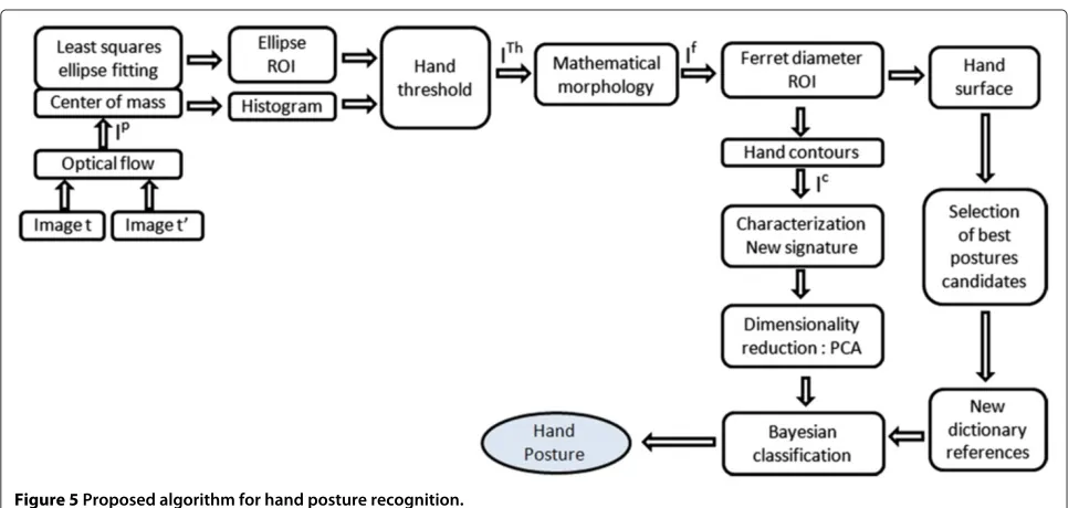
6.1 Summary of the proposed methods
Figure 5 depicts the overall structure of our algorithm. Referring to an analogous scheme in [4], one can appre-ciate some improvements that were recently carried out to further enhance the detection of hand contours, essentially the optical flow combined with elliptic fitting, a dedicated preprocessing to help in the selection of the largest set of connected pixels, and a new method to ensure the invariance to rotation.
a)
100 200 300 400 500 600 100
200
300
400
b)
100 200 300 400 500 600 100
200
300
400
c)
50 100 150 200 250 300 100
200
300
d)
50 100 150 200 250 300 100
200
300
e)
50 100 150 200 250
50 100 150 200 250
f)
50 100 150 200 250
50 100 150 200 250
6.2 Numerical complexity of the proposed methods To express the computational complexity of the proposed method, let us assume that iff denotes the actual com-putational complexity depending on the parameters of the methods, and ifgis another function of these parameters, we can use the notationf =O(g), if and only if there exist a positive constantasuch that for all sufficiently large val-ues of the parameters, the numerical complexity f is at mostamultiplied by g in absolute value. Therefore, we will use this notation by considering the case where the computational load is the highest.
We will consider successively the methods applied both off-line and on-line, only off-line, and then only on-line.
•The following steps are applied both off-line to build the reference database, and on-line to identify a hand pos-ture. The first one, optical flow, is based on the computa-tion of subsampled images from the two images available at timetand at timet+1. LetNt be the largest
dimen-sion of the initial image (for instance the number of rows for a tall image) at timetor at timet+1. Spatial deriva-tives are computed for each subsampled image. These are pixel-to-pixel operations based on subtractions, so the
order of magnitude of such computations isO(Nt2)
oper-ations (at most a multiple of the number of pixels). The subsequent preprocessing operations are performed on a ROI extracted from imaget. The largest dimension of this ROI is marginally larger than, or equal toN, so at most a multiple ofN(see Subsection 3.3). These preprocessing operations are the least-squares ellipse fitting which is not computationally dominant, and then the mathematical morphology filters, yielding a computational complexity ofO(sN2), wheres is the number of pixels in the struc-turing elements [39]. As s is fixed for any image, this complexity is equivalent toO(N2). To compute the pro-posed signature, computing and storing one element of signature Z requires three multiplications, two subtrac-tions, one addition, and one square root. Assuming that multiplications and square root are the most computa-tionally intensive/costly and assuming that in the worst case, 1 pixel is present for each levelpand for each direc-tion of generadirec-tion Di, this yields a complexity of 4 P Q,
that is, an order of magnitude ofO(PQ). Sorting one row of matrixZrequiresO(Qlog(Q))operations, and sorting all rows requiresO(PQlog(Q))operations.
•The following steps are only applied off-line: the com-putation of the mean characteristics Uh, μh for each of
a)
100 200 300 400 500 600 100
200 300
400
b)
100 200 300 400 500 600 100
200 300
400
c)
100 200 300
100
200
300
d)
100 200 300
100
200
300
e)
50 100 150 200 50
100 150
200
f)
50 100 150 200 50
100 150
200
the 11 hand postureshis performed by PCA, which relies on the computation of leading singular vectors. For this purpose we use the fixed point algorithm (see Subsec-tion 5.1). This algorithm yields a complexityO(K(PQ)2+ MhK(PQ)2) [37], where Mh is the number of sample
images for the considered class, andKthe number of lead-ing slead-ingular vectors. The inversion of matrixhby Gauss Jordan elimination requiresO(K3)operations.
• The following steps are only applied on-line: for any test image, as there exist 11 candidate hand pos-turesh, the computation of the 11 distances between the scalar sphericity criterionStof the test image and the 11
mean sphericity criteriaSh. After preselection of six
pos-tures, the six Mahalanobis distance values Dm between
the compressed test vector UThx and the mean vector
μh. This yields 11+ 6O(K) operations. Additionally, a sorting operation is performed for each distance, with an associated computational complexity 11 log(11) and 6 log(6).
Finally,O(Nt2+N2+PQ+PQlog(Q)+11(K(PQ)2+ MhK(PQ)2+K3))operations are performed off-line, and O(Nt2+N2+PQ+PQlog(Q) +6K)+ δ operations,
whereδis a constant not depending on the parameter val-ues, which are performed on-line. Considering sufficiently large values ofNt,N,P,Q, andMh, we derive the following
simplified expressions:
• O(Nt2+N2+PQ(log(Q)+KMhPQ)+K3)
operations off-line;
• O(Nt2+N2+PQlog(Q)+K)operations on-line.
Eventually, we can further simplify these expressions: in the processed image, the ROI containing the hand is large enough to ensure N > Nt
10. So, O(N2) is equiva-lent toO(Nt2), and we can derive the following simplified
expressions:
• O(N2+PQ(log(Q)+KMhPQ)+K3)operations
off-line;
• O(N2+PQlog(Q)+K)operations on-line.
Firstly, we can notice that the computational complexity of the off-line methods is of one order of magnitude higher inPQ. This is due to the computation of the mean char-acteristicsUh,μh, which is only performed off-line. The
a)
100 200 300 400 500 600
100
200
300
400
b)
100 200 300 400 500 600
100
200
300
400
c)
100 200 300 400 500
50
100
150
200
250
d)
100 200 300 400 500
50
100
150
200
250
e)
50 100 150 200 250
50
100
150
200
250
f)
50 100 150 200 250
50
100
150
200
250
off-line operations also include the termK3, because the inverse of each covariance matrix is performed off-line. These computations have no influence on the speed of the hand posture recognition process. Secondly, we remind that the computational load required in practice for each step depends on the programming language which was used to implement it.
In Section 7, the results obtained are presented, in terms of recognition and also computational time performance.
7 Results on hand posture recognition and discussion
In the database, the images have a size of either 320 × 240 or 640×480 depending on the camera used at the acquisition step. The machine used has a 2-core pro-cessor running at 3.2 GHz, using Matlab. This result section falls into two subsections: firstly, we present the results of hand contour segmentation with optical flow and adequate preprocessing; secondly, we exemplify the discriminative capabilities of the signatureZand present the statistical results of hand posture recognition obtained with PCA and Mahalanobis distance.
7.1 Hand contour segmentation with optical flow We present successively some requirements for the opti-cal flow to work optimally: an initial exemplification of optical flow method applied to a white and a dark-skinned hand and to a colored moving hand wearing a glove and a second exemplification of all preprocessing methods, including optical flow, which yield the binary imageI con-taining the hand contour. This binary image is smaller than the input color images, and its size depends on the distance between the hand and the camera. We have cho-sen three levels for the pyramids while applying optical flow.
7.1.1 Requirements for the experimental conditions and
subsequent image rejection
Adapting optical flow exhibits not only advantages but also requirements on the experimental conditions and specific preprocessing. The required experimental con-ditions for which the optical flow works optimally are as follows [22]: between two frames, the hand should move slowly enough to avoid blurred images and the brightness must be constant, so that a moving pixel does not change in appearance; to avoid the presence of odd
a)
100 200 300 400 500 600
100
200
300
400
b)
100 200 300 400 500 600
100
200
300
400
c)
100 200 300 400
100
200
300
400
d)
100 200 300 400
100
200
300
400
e)
50 100 150 200 250 300
100
200
300
f)
50 100 150 200 250 300
100
200
300
points among the set of moving points detected by opti-cal flow, the background color must be different from the hand color, which is easy to set including with complex backgrounds.
We comply with these requirements and cope with odd detected points as follows:
• Firstly, while running optical flow, we choose a time increment between two frames which is small enough. To reduce the computational load and reach a delay between two subsequent frames which is as low as possible, we set the best empirically chosen parameters: we reduced the number of moving points taken into account by optical flow to 1,000, which permitted to reach a time delay of 110−1s between two frames.
• Secondly, while creating our learning database, we reject the frames which yield such characteristics: if one axis of the fitting ellipse (see Subsection 3.3) is larger than the image size, or if the large axis is larger than three times the small axis. We consider that in these cases, the moving points detected by optical flow do not permit to delimitate a reliable region of interest around the hand.
The drawback/limitation for a user point of view is that the hand posture recognition may take a bit longer for the recognition result, until the luminosity does not vary too much, or until his hand moves slowly enough.
7.1.2 Performance assessment on colored hands
The main advantages of the proposed method, which adapts optical flow instead of the classically usedYCbCr
mapping, are as follows: it handles the case of colored hands, such as people wearing gloves of any color, or hands of dark-skinned people. This is a significant advan-tage over the existing methods which usually fail as soon as the hand surface cannot be distinguished from the background in the Cr component. See for instance the
issues concerning the background presented in [11,18-20] and the problem of body parts which are present in the scene and which are not the hand [14]. Also, we adapt optical flow to isolate a region of interest containing the hand, which reduces the computational load of the sub-sequent steps. Conversely, in comparative methods, when YCbCr mapping is performed, the threshold operation
is applied to the whole image, which is computationally more costly, and as such increases the probability to get noise pixels.
a)
100 200 300 400 500 600
100
200
300
400
b)
100 200 300 400 500 600
100
200
300
400
c)
100 200 300 400
100
200
300
400
d)
100 200 300 400
100
200
300
400
e)
50 100 150 200 250 300
100
200
300
f)
50 100 150 200 250 300
100
200
300
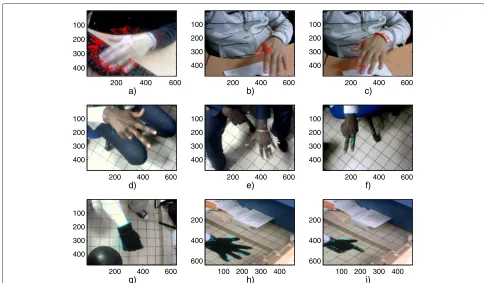
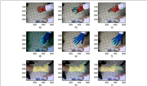
Figure 6 shows the results obtained by the opti-cal flow on hands from white people (Figure 6a,b,c), dark-skinned people (Figure 6d,e,f ), and hands wearing black gloves (Figure 6g,h,i); Figure 7 shows the results obtained by optical flow on a red (Figure 7a,b,c), a blue (Figure 7d,e,f ) and a yellow hand (Figure 7g,h,i). It consists of pixels which are about to move between the current and the next frame. It can be expected from these pixels that they delimitate correctly an ROI around the moving hand: the results obtained by the optical flow can be used to perform the preprocessing step.
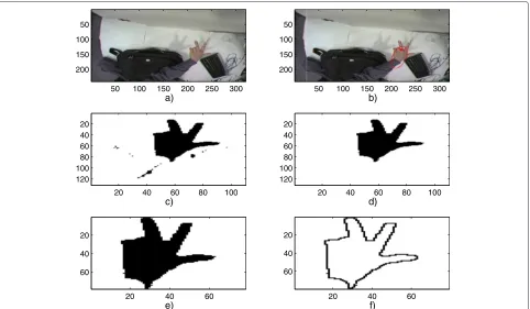
As shown in Figures 6 and 7, the optical flow method provides a set of points, among the moving points of the scene. Since a sparse version of the optical flow was chosen, these points are mainly focused on the hand contour. In Figure 8 we exemplify the steps of the pro-posed algorithm for the segmentation of hand contour, on a white-skinned hand, and a posture of type ‘3’ . This algorithm starts with an adaptation of the optical flow and includes a thresholding operation. In Figure 8a, we show the processed image. The five other figure parts in Figure 8 illustrate the five preprocessing steps of Subsection 3.3. In Figure 8b, we show the moving points provided by the optical flow (colored in red),
their center of mass (as a large red square), and the fit-ting ellipse (also in red). The image ITh of Figure 8c is the intersection of all 1-valued pixels of the thresh-olded R, G, and B bands. This thresholding operation is selective enough to isolate correctly the hand sur-face, but noise pixels appear in ITh as illustrated in Figure 8c. Figure 8d illustrates the advantages of the third preprocessing presented in Subsection 3.3: it allows the removal of the undesired pixels which are present in the thresholded image ITh. We present in Figure 8e the ROI which is the smallest square image contain-ing the hand. In Figure 8f, we present the hand contour obtained by Roberts linear filtering applied to the image of Figure 8e.
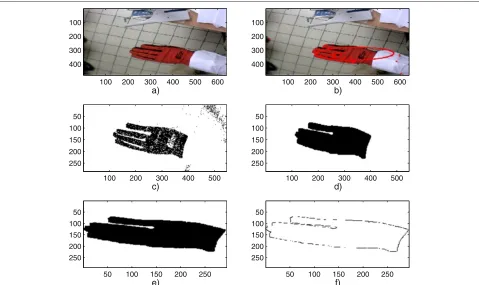
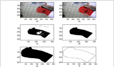
In Figures 9, 10, 11, 12, 13, 14, 15, 16, we further exem-plify the method in the same way, with a dark-skinned hand, and a hand wearing a black, a red, a blue and a yellow glove.
The results obtained on these sample images show the ability of the proposed method to handle not only white but also colored hands.
7.2 Hand posture characterization and recognition Some experiments performed with our database allowed us to determine and set the best values for parametersP
a)
100 200 300 400 500 600 100
200 300 400
b)
100 200 300 400 500 600 100
200 300 400
c)
100 200 300 400
100
200
300
400
d)
100 200 300 400
100
200
300
400
e)
50 100 150 200 250 300 100
200
300
f)
50 100 150 200 250 300 100
200
300
andQ. To generate the signatureZwhose components are zp,i, withp= 1,. . .,P, andi = 1,. . .,Q(see Equation 1)
a value ofP = 24 levels is large enough to get an exclu-sive signature for each posture and small enough to get a reasonable computational load. A valueQ = 120 yields a good compromise between computational cost and dis-criminative capability. While performing the recognition of any test image, the regularization termin Equation 3 is fixed to 10−4max()where max(·)stands for maximum value.
Firstly, we illustrate the discriminative capability of the method when one test image is considered. Secondly, we provide a statistical study involving all images of the test database. For each of the 11 classesh, we have used on averageMh=250 images in the learning database and 150
images in the test database. In the test database, for each class, one image out of four contains a hand from either a colored person, or wearing a glove, either black, red, yel-low, or blue. The same postures forming 11 classes are used in the comparative studies [3,4,10,40]. The images are taken from the database which is used in [10] and which was created within our laboratory in the past few years. Very similar images are also used in [40] though
the hands seem to cover a wider part of the image, thus offering supposedly a better resolution. We enriched the existing database with some additional images of dark-skinned hands and hands wearing black, yellow, blue, and red gloves.
7.2.1 Discriminative capability of the proposed signature
For a given image of the test database, we aim at ver-ifying the discriminative capability of the proposed sig-nature. Let us assume this test image to belong to class h1 ∈ {1,. . ., 11}, and let Zh1 be the signature com-puted from this image. Let Z¯h2 be the mean signature obtained from all images of the learning database for class h2 ∈ {1,. . ., 11}. The proposed signature will be discriminative if these two conditions hold: Zh1 should be close toZ¯h2 when h1 = h2, and far from Z¯h2 when h1=h2.
We compute the normalized distancedh1,h2= ||Z|| ¯h1Z− ¯Zh2|| h2|| , where||·||denotes Frobenius norm, for one image of each class h1.
Firstly, let us comment on some features concerning all postures: when h1=h2, the mean of the distance values is 4.7 10−1; when h1=h2, the mean of the distance values
a)
100 200 300 400 500 600 100
200
300
400
b)
100 200 300 400 500 600 100
200
300
400
c)
100 200 300 400 500 600 100
200
300
400
d)
100 200 300 400 500 600 100
200
300
400
e)
100 200 300
100
200
300
f)
100 200 300
100
200
300
a)
100 200 300 400 500 600 100
200
300
400
b)
100 200 300 400 500 600 100
200
300
400
c)
100 200 300 400 500 600 100
200
300
d)
100 200 300 400 500 600 100
200
300
e)
100 200 300
100
200
300
f)
100 200 300
100
200
300
Figure 16Yellow hand 2 and steps of the proposed method.(a)Processed image.(b)Moving points, fitting ellipse (indicated by red dots and a red ellipse), and center of mass (indicated by a red square).(c)Threshold imageIThin the ROI defined from the fitting ellipse.(d)Result obtained after mathematical morphology operations.(e)If-square ROI whose height is the maximum Ferret diameter of the hand.(f)Ic, obtained from Roberts linear filtering, containing the expected hand contour.
is 6.5 10−1; and whatever h1∈ {1,. . ., 11},dh1,h2is mini-mum when h1=h2. The distance between two signatures is then the closest when these signatures correspond to images with the same postures.
Secondly, let us focus on specific features: the smallest distance values obtained in the case where h1 = h2 are d4,1 = 4.8 10−1andd8,9 = 4.9 10−1, that is, for couples of visually close postures. The distanced10,6 = 5.8 10−1 is also significantly smaller than the mean value 6.5 10−1. The distance valuesd4,1,d8,9, andd10,6=5.8 10−1remain more elevated than the mean value 4.7 10−1 obtained when postures are the same.
The reliability of the signature must be proven with a statistical study as will be described in the following.
7.2.2 Statistical study of posture recognition performance
To perform dimensionality reduction (see Subsection 5.1), the number of dominant singular values retained while performing PCA is fixed toK=60. This number, empiri-cally chosen, should be higher than the number of candi-date postures (11), and small enough to ensure a reduced computational load. This value of K is also the number of rows and columns in h, a small value which eases
its inversion to compute the Mahalanobis distance in Equation 3.
To assess the effectiveness of our proposed technique, we have compared our method with three similar meth-ods: The first method combines Gabor filter, PCA, and support vector machine (SVM) [40]. The second method relies on Fourier descriptors [10,13]. The third one uses the same principles for signature generation [3,4], without however sorting the signature components and differing in the computation of the binary imageI which is used as an input for the computation of the contour signature (see [3,4]). This binary image is obtained using YCbCr
mapping, a threshold applied to theCr component and
mathematical morphology operations. Additionally, in [4], PCA is already used to reduce the dimensionality of the data, but the preselection of candidate postures is not per-formed with the proposed sphericity, but with a surface criterion.
In Table 1, we depict the results obtained withYCnbCr
Table 1 Confusion matrix (in %, precision 0.1)[13]
1 2 3 4 5 6 7 8 9 10 11
1 86.6 0 0 0 0 0 0 0 0 0 0
2 0 90.8 0.4 0.4 0.2 0.2 0.1 0 1.7 0.1 0.1
3 0 0.7 96.4 0.5 0.4 1 0.4 0 0.7 0.1 3.3
4 5.5 0 0 60.8 0 0.1 0.4 0 0 0 0
5 2.9 1.8 0.5 35.9 97.8 0.9 7.8 3.2 4.9 20.2 0.1
6 4.6 0.1 0 0.1 0.3 94.3 0.8 0 0.2 2 0
7 0.2 0.4 0.1 0.7 0.5 1.1 80.6 8.3 0.3 2.8 0
8 0 0.2 0 0.3 0.3 0.1 1.9 64.8 2.8 0.5 0
9 0 5.9 1.7 0.9 0.3 0.4 6 23.2 88.6 0.9 0.4
10 0 0.1 0.1 0.3 0 0.2 0.8 0.4 0.2 73.4 0
11 0.2 0.2 0.8 0.1 0.1 1.6 1.1 0.1 0.7 0 96.2
Obtained with Fourier coefficients and Mahalanobis distance. Italic features are the true-positive recognition rates.
to preserve details: contours are smoothed, and subtle dif-ferences such as the presence of one supplementary finger as can be seen to occur between posture 4 and posture 5, and between posture 8 and posture 9, are not detected when Fourier coefficients are used. On the other hand, our method based on signature generation technique offers a 1-pixel resolution and does not encounter such problems. Table 2 shows the confusion matrix obtained with the signature Z, PCA, and Mahalanobis distance [4]. This method is based onYCbCrmapping. It clearly shows that
this method gives good results, except for posture 4 which is recognized as posture 5 with 11.3 % of the cases, pos-ture 8 is recognized as pospos-ture 9 with 25.6 % of the cases, and posture 5 as 4 in 5.5 % of the cases.
The confusion matrix obtained with the method pro-posed is presented in Table 3.
The comments which result from the confusion matrix of Table 3 obtained with the method proposed in this paper fall into two parts:
Firstly, concerning the true-positive recognition rates, they are more elevated with our method using optical flow, signatureZ, PCA, and Mahalanobis distance for pos-tures 2, 3, 4, 5, 6, 7, 8, 9, and 10, compared to the case whereYCbCrmapping is used. The true-positive
recogni-tion rates are better in particular for postures 4, 5, and 9, and even much better for posture 8, in which it increases from 64.8% in [10] and 67.4% in [4] to 96.1% with the method proposed in this paper.
Secondly, concerning the false-positive rates, we notice that they are larger than 0 for the couples {h1, h2} for which dh1,h2 is rather low, that is, for the couples of postures which are visually the closest.
Table 2 Confusion matrix (in %, precision 0.1)
1 2 3 4 5 6 7 8 9 10 11
1 97.7 0 0 0 0 0 0 0 0 0 0
2 0 100 0 0 0 0 0 0 0 0 0
3 0 0 90.8 0 0 0 2.3 4.7 2.4 0 0
4 0 0 0 86.4 5.5 0 0 0 0 0 0
5 2.3 0 2.3 11.3 91.7 0 0 0 0 0 0
6 0 0 0 0 0 95.5 0 0 0 0 0
7 0 0 0 0 0 0 93.1 2.3 0 0 0
8 0 0 0 0 0 0 2.3 67.4 2.4 0 0
9 0 0 4.5 2.3 2.8 0 2.3 25.6 92.8 2.1 0
10 0 0 0 0 0 4.5 0 0 2.4 97.9 0
11 0 0 2.4 0 0 0 0 0 0 0 100
Table 3 Confusion matrix (in %, precision 0.1)
1 2 3 4 5 6 7 8 9 10 11
1 96.3 0 0 0 0 0 0 0 0 0 0
2 2.4 100 0 5.5 1.6 0 0 0 0 0 0
3 0 0 99.1 0 0 0 0 0 0.7 0 0
4 1.2 0 0 92.6 0 0 0 0 0 0 0
5 0 0 0 1.8 98.3 0 0 0 0 0 0
6 0 0 0 0 0 95.2 0 0 0 0 0
7 0 0 0 0 0 0 99.2 2.3 0 0 0
8 0 0 0 0 0 0 0 96.1 1.5 0 0
9 0 0 0.9 0 0 0 0.8 1.5 97.7 0 0
10 0 0 0 0 0 4.7 0 0 0 100 0
11 0 0 0 0 0 0 0 0 0 0 100
Obtained with optical flow, proposed signature, PCA, and Mahalanobis distance. Italic features are the true-positive recognition rates.
We remind also that the results presented in Table 3 were obtained with hands of various colors, and therefore a somehow richer database than in [10] and [4], where only white hands are considered. This attractive perfor-mance relies on the quality of the binary imagesIwhich are provided to the signature generation method, unlike the YCbCr mapping which results in blurring the edges
and reduces the contrast between hand surface and back-ground on theCrchannel. The second preprocessing step
in Subsection 3.3 consists in thresholding the R,G, and B channels of the RGB color image where the contrast between hand surface and background is increased. The three threshold images are then combined to get a single binary image. Selecting a region of interest with opti-cal flow permits to avoid unexpected noise pixels in this binary image.
These good recognition results are also due to the dis-criminative capabilities of the signature.
In the following as shown in Table 4 we consider the per-formance of the proposed method against the other three methods in terms of speed.
Table 4 Proposed and comparative methods, comparison of performances
Classification method Speed System Soft (frames/s) (GHz)
a PCA+SVM 4 3.4 C
b Fourier + Mahalanobis 20 2 C
c PCA + Mahalanobis 6 3.1 Matlab
d OF + PCA + Mahalanobis 4 3.1 Matlab + C
a, Gabor-filtered + PCA + SVM [40]; b, Fourier descriptors (FD1) + Mahalanobis; c,YCbCrmapping, PCA, and Mahalanobis distance [4]; d, proposed method involving optical flow (OF).
As mentioned in Subsection 7.1, while applying the optical flow, it is necessary to wait 1 10−1 s before cal-culating the velocity vectors for a couple of imagestand t+1 in order to work in appropriate conditions. The time required by the optical flow component to calculate the velocity vectors and the moving points is much shorter around 3.3 10−2 s, which is the time interval between two frames provided by the camera. The following com-putational times are obtained excluding the optical flow: The off-line methods require 102 s to process the 2,750 images of the learning database, reaching a mean rate of 27 frames/s. For the 1,650 images of the test database, the preprocessing step requires 410 s, that is, 4 images per second; the on-line recognition out of the binary images requires 22 s for the 1,650 images, that is, 27 images per second. Therefore, the preprocessing operations are the most computationally intensive tasks and are the limiting factors. In Table 4 (d), the overall mean rate of 4 frames/s is mentioned. It concerns the on-line recognition step.
The method combining Gabor filter, PCA, and SVM [40] processes 4 frames/s as well (see Table 4 (a)). Fourier descriptors programmed in C++ [13] are faster, namely 20 frames/s (see Table 4 (b)). The method involvingYCbCr,
PCA, and Mahalanobis distance [4] (Table 4 (c)) mapping is faster (6 frames/s) but it exhibits a major drawback as all methods usingYCbCrmapping: it does not handle colored
hands.