Characterization of a Class of Error Correcting
Frames for Robust Signal Transmission over
Wireless Communication Channels
Gagan Rath
IRISA, INRIA, Campus de Beaulieu, 35042 Rennes, France Email:[email protected]
Christine Guillemot
IRISA, INRIA, Campus de Beaulieu, 35042 Rennes, France Email:[email protected]
Received 14 July 2003; Revised 24 May 2004
Joint source-channel coding has been introduced recently as an element of QoS support for IP-based wired and wireless multime-dia. Indeed, QoS provisioning in a global mobility context with highly varying channel characteristics is all the most challenging and requires a loosening of the layer and source-channel separation principle. Overcomplete frame expansions have been intro-duced as joint source-channel codes for erasure channels, that is, to allow for a signal representation that would be resilient to erasures in wired and wireless channels. In this paper, we characterize a class of frames for error correction besides erasure recov-ery in such channels. We associate the frames with complex number codes and characterize them based on the BCH-like property of the parity check matrices of the associated codes. We show that, in addition to the BCH-type decoding, subspace-based al-gorithms can also be used to localize errors over such frame expansion coefficients. When the frame expansion coefficients are quantized, we modify these algorithms suitably and compare their performances in terms of the accuracy of error localization and the signal-to-noise ratio of the reconstructed signal. In particular, we compare the frames associated with lowpass DFT, DCT, and DST codes, which belong to the defined class, in terms of their error correction efficiency.
Keywords and phrases:frame theory, error correction, compression, block transforms, wireless communication.
1. INTRODUCTION
The development of “Beyond 3G” (B3G) or “4G” networks and applications with all-IP-based seamless and ubiqui-tous service provisioning across heterogeneous infrastruc-tures presents a number of technological challenges. Provid-ing IP-based audio and video communications at the same, or at least comparable, “carrier class” and bandwidth effi -ciency as the corresponding circuit-switched subsystems of 3G and 2G remains an issue to be solved. There is a growing awareness and understanding that efficient QoS provision-ing in a global mobility context with highly varyprovision-ing chan-nel characteristics (bandwidth, throughput, error rates, fad-ing, and erasure characteristics, etc.) requires a loosening and a rethinking of the end-to-end and layer separation princi-ple. In particular, it is becoming a common understanding that vertical cross-layer cooperation may be beneficial be-cause of both of the error and erasure resilience capabilities of emerging coding technology and of the idiosyncrasies of the wireless links. Both the link layer including the radio bearer
system and the higher layers will indeed benefit from QoS-related information exchange.
The robust header compression (ROHC) framework [1], and the new UDP-Lite protocol—possibly delivering erro-neous packets to the application layer [2]—are strong steps towards a loosening and a rethinking of the end-to-end and the layer separation principle. Situated between link and IP layers, the ROHC [1] framework addresses the problems of spectrum and bandwidth scarcity and of packet header cor-ruption due to bit errors characterizing wireless links. The fact that, for some applications, erroneous packet payloads can be valuable and better to cope with than the lost ones, has inspired the introduction of the UDP-lite transport protocol [2]. Assuming ROHC, UDP-lite, and an appropriate inter- or cross-layer signaling mechanism in action, this paper consid-ers a joint source-channel coding scheme in the application layer which is based on the use of a certain class of frames.
in a Hilbert space which span the space but may contain larger number of vectors than a basis. The redundancy in-herent in a frame makes the expansion resilient to additive and quantization noise and imparts stability to reconstruc-tion. Overcomplete frame expansions for providing robust-ness to erasures in communication networks can be regarded as joint source-channel codes.
In this paper, we characterize a class of discrete frames which can be used for error correction besides erasure re-covery. We associate the frames with complex number codes [5] and characterize them based on the structure of the par-ity check matrices of the associated codes. The structure of the codes is a generalization of that of the BCH-DFT codes [6,7, 8]. We show that there are also other codes such as the discrete cosine transform (DCT) [9] and the discrete sine transform (DST) codes which have the same structure. Un-like DFT codes, DCT and DST codes are neither cyclic nor BCH. However, we show that a BCH-like decoding algo-rithm can be applied to localize and decode errors in such codes. We stress on the frame-theoretic formulation rather than the coding-theoretic approach because the codevectors need to be quantized before being transmitted. Introduction of quantization leads to errors beyond the error correcting capability of the codes and thus makes the underlining the-ory inefficient. In this context, the frame theory comes in hand since it can analyze the reconstruction errors and study the usefulness of the particular frame.
The second contribution of the paper is the introduction of subspace algorithms for localizing errors in the frame ex-pansion coefficients. Subspace methods are popular in the di-rection of arrival (DOA) estimation [10,11] and they can be applied to localize errors in DFT codes [12]. Here the sub-space methods are extended to the generalized codes case. In the case of DFT codes, the locations of errors correspond to discrete frequencies and, therefore, the adaptation of sub-space algorithms [12] seem straightforward. However, for the generalized codes defined here, the locations of errors may not correspond to any frequency, and hence the application of subspace methods is not so obvious. The motivation for introducing subspace methods is to increase the localization accuracy of errors when the coefficients are quantized. We compare the performances of the proposed subspace algo-rithm and the BCH decoding with lowpass DFT, DCT, and DST frames when they are used for transmitting a Gauss-Markov source and images.
2. FINITE FRAMES REVISITED
Consider theK-dimensional Euclidean complex space, that is,CK. A set ofK-dimensional vectorsΦ
G≡ {ϕk}Nk=1is called
a frame if there existB1>0 andB2<∞such that
B1x2≤
N
k=1
x,ϕk
2
≤B2x2, ∀x∈CK, (1)
wherex,ϕkdenotes the inner product ofxandϕk, andx denotes the Euclidean norm ofx[4].B1andB2are called the frame bounds. The inner productx,ϕkgives thekth frame
expansion coefficient ofx. Any finite set of vectors that spans
CK is a frame. Therefore a frame will always haveN ≥ K. The ratioN/K is normally referred to as the redundancy of the frame. The frameΦGis associated with a frame operator
Gwhich is defined as follows:
(Gx)k≡
x,ϕk
, fork=1, 2,. . .,N. (2)
Thus the frame expansion coefficients ofxare given byGx. A frame is calledtightif its bounds are equal, that is,B1=B2. Hence ΦG is tight if and only ifGhG = BIK, where B =
B1 = B2. This implies that the columns ofG are orthogo-nal. A frame is called normalizedor uniform if each frame vector has length equal to 1 [4]. Associated with the frame
ΦG, there exists a dual frame whose frame operator is given asG=G(GhG)−1. Given the frame expansion coefficients of
any vectorx, the vector can be reconstructed using the dual frame operator asx = Gh(Gx). The conjugate transpose of the dual frame operator is the pseudoinverse of the frame op-erator, and it minimizes the reconstruction error [4]. For de-tails about frame theory and signal representation with over-complete sets, the reader is referred to [13].
3. ERROR CORRECTING FRAMES
Frames provide redundant representations of signals. The re-dundancy of the representation can be utilized for various purposes such as providing stable reconstructions, enhanc-ing the quality of the reconstructions, and providenhanc-ing robust-ness against additive noises. Recently frames have been pposed for use in communication channels for providing ro-bustness to erasures [3,4]. Even if some of the frame expan-sion coefficients are lost during the transmission, the mes-sage signal can still be reconstructed from the received co-efficients. In addition, the quality of the reconstruction im-proves as the number of lost coefficients decreases. This is contrary to the case with classical critical representation of a signal when the loss of a coefficient cannot be recovered without the help of error control coding.
The frames used for providing robustness to erasures must possess certain desired properties. For example, with a frame expansion inCK, in order to reconstruct the message with anyKreceived coefficients, the set of frame vectors asso-ciated with the received coefficients must also be a frame [4]. Further, in order to minimize the reconstruction error due to quantization of the coefficients, this frame must be tight [4]. Not all frames do possess these properties. In the following we characterize a class of frames which cannot only recover erased coefficients but also correct additive errors in frame coefficients.
be given as
G=V1ΣVh
2, (3)
whereV1is anN×N unitary matrix,V2 is aK×K uni-tary matrix, andΣis anN×K matrix havingN−K null row vectors.H can be obtained by taking those columns of
V1which have the same indices as those of the null row vec-tors ofΣ. SinceV1is unitary, the columns ofHare linearly independent andHhG=0(
N−K)×K.
Notice that, in the frame-theoretic formulation, the rows of the matrix G are the basic elements; they form a span-ning set for aK-dimensional space. This is in contrast with the coding-theoretic formulation where the columns of the matrix G are the basic elements; they form a basis for a
K-dimensional subspace of anN-dimensional space. For a given message vector, the vector of frame expansion coeffi -cients and the codevector are one and the same.
The number of complex errors that this frame can detect and correct depends on the minimum distance of the associ-ated code. The Hamming distance between two codewords is defined as the number of positions or indices in which they differ from each other [5]. In the following, we characterize a class of codes which are BCH-like: their parity check matrices have similar properties as those of BCH codes so that a BCH decoding algorithm can be applied to correct errors. This will equivalently characterize a class of frames which are associ-ated with those codes. We consider the “errors only” case here since the extension to errors with erasures is straightforward.
3.1. BCH-like complex codes
For notational convenience, we set d = N−K, where d
is a positive integer. Let there be d complex polynomials
p1(x),p2(x),. . .,pd(x) of orderd−1 each, where theith poly-nomial is defined as
pi(x)=ai1+ai2x+· · ·+aidxd−1. (4)
Let the polynomials be such that the coefficient matrixA, which is given as
A≡
is nonsingular. Let f be a one-to-one nonzero complex func-tion defined on the index set{0, 1,. . .,N−1}. Let the ele-ments ofHhbe specified ash
i j=ujpi(f(j−1)), 1≤i≤d, 1≤ j≤N, whereu1,. . .,uNare nonzero scalars. ThenHis a parity check matrix of a maximum distance separable (MDS) complex code. Such a code can correct up tod/2errors and can recover up toderasures.
To prove the above assertion, we see that the conjugate transpose of the parity check matrix can be expressed as
Hh=AXU, (6)
where X is d × N with ith column equal to [1,f(i −
1),. . .,fd−1(i−1)]t and U is a diagonal matrix with the
ith diagonal entry equal to ui. Since f is one-to-one and nonzero, anyk,k ≤ d, columns ofXare linearly indepen-dent. As a result, anyk,k≤d, columns ofHare also linearly independent. Therefore the minimum distance of the code is
d+ 1 and the code is MDS [5].
3.2. Examples
3.2.1. DFT codes
An (N,K) DFT code is a linear block code whose generator matrix consists of anyKcolumns from the inverse DFT ma-trix of orderN[6]. A parity check matrix of the code consists of the remainingN−Kcolumns of the inverse DFT matrix. Since the DFT matrix is unitary, the frames associated with DFT codes are tight. If the parity frequencies are spaced byα, whereαis relatively prime toN, then the DFT code is a BCH code in the complex field [6]. Let the parity frequencies be denoted by 0,α,. . ., (d−1)α. Then the conjugate transpose of the parity check matrix is given as
Hhf =
f has a similar structure as that ofHhwithX =Hh
f,A =Id, andU =IN.
Id and IN denote identity matrices of orderd and N, re-spectively. Clearly, the function f is defined as f(i) =wiα, 0 ≤ i ≤ N−1. Real BCH-DFT codes are special cases of complex BCH-DFT codes [6]. If the parity frequencies of a complex BCH-DFT code are such that the complex conju-gate of every column of the generator matrix also belongs to it, then, through elementary column operations, the DFT code can be made real. For example, a real BCH-DFT code is defined by the following generator matrix [7,8,14,15]: this code, the parity check matrix is given by
and U is a diagonal matrix with the ith diagonal entry equal tow((K+1)/2)i,i = 0,. . .,N−1. Obviously, hereA =
Id and the function f is given as f(i) = wi, 0 ≤ i ≤
N−1. Since the parity frequencies correspond to the high-frequency indices, this code can also be termed as a lowpass code [6]. We can have similar formulation for a highpass DFT code.
3.2.2. DCT codes
An (N,K) DCT code is a linear block code whose generator matrix consists of anyKcolumns from the inverse DCT ma-trix of orderN[9]. Here we use the inverse DCT matrix in or-der to be consistent with the definition of DFT codes. A par-ity check matrix of the code consists of the remainingN−K
columns of the inverse DCT matrix. DCT codes are real block codes. Since the DCT matrix is orthogonal, the frames as-sociated with DCT codes are tight. Consider the DCT code whose parity frequencies correspond to the highest N−K
frequencies. Here we consider the type-II DCT matrix whose (i,j)th element is given as
The parity check matrix of this code can be given as
Ht
By rearranging the rows in reverse order and using basic trigonometric relations, it can be expressed as
Ht
Using the identity [16]
sin(nβ)=sinβ
this can be factorized as
Hct=AXU, (15) nonsingular matrix. Obviously, the function f is given as
if the parity frequencies are spaced byα, whereαis relatively prime toN, the DCT code may not be BCH-like becauseA
may not be nonsingular.
3.2.3. DST codes
An (N,K) DST code is a linear block code whose generator matrix consists of anyKcolumns from the inverse DST ma-trix of orderN. A parity check matrix of the code consists of the remainingN−Kcolumns of the inverse DST matrix. Like DCT codes, DST codes are real block codes. The frames as-sociated with the DST codes are also tight. Consider the DST
code whose parity frequencies are the highestN−K frequen-cies. Here we consider the type-II DST matrix whose (i,j)th element is given as
θ(i,j)=
The parity check matrix can be given as
Ht
By rearranging the rows in reverse order, the matrix can be expressed as
Hst=
Using the identity [16]
cos(nβ)=1
this can be factorized as
A is a lower triangular nonsingular matrix. Therefore the above DST code is BCH-like and can correct up tod/2 er-rors. This is a lowpass DST code since the parity frequencies are the higher frequencies. We can similarly have a highpass BCH-like DST code whose parity frequencies correspond to the low-frequency indices. Similar to DCT codes, parity fre-quencies spaced byα, whereαis relatively prime toN, may not result in a BCH-like DST code.
4. DECODING OF ERRORS WITH UNQUANTIZED FRAME EXPANSIONS
The class of complex codes defined in the previous section is a generalization of the complex BCH codes. In the special case whenA=IdandU=IN, they are BCH. It is easy to see that the DFT codes defined by the parity check matrixHh
fare BCH whereas the DCT and the DST codes are not BCH. In fact, the DCT and the DST codes are not even cyclic. Never-theless, the BCH decoding algorithm can still be applied to decode the errors provided the number of erroneous coeffi -cients is less than or equal tod/2. In the following, we first present a syndrome decoding algorithm which is analogous to the syndrome decoding algorithm for complex BCH codes [17]. Then we present a subspace-based algorithm which fol-lows the lines of MUSIC algorithm for DOA estimation in array signal processing.
4.1. Syndrome decoding
Letrdenote the received vector of coefficients when the ac-tual coefficient vectory is corrupted by the error vector e. Hencer = y+e. We assume thatehasνnonzero compo-nents whereν≤ d/2. The syndrome of the received vector is given as drome vector. Recall thatAis invertible by definition. Since
r=y+e, we get
XU(y+e)=XUe=z. (25)
The above relation follows sinceXUis also a parity check matrix for the same code resulting inXUy=0d×1.
at the indices of nonerroneous coefficients, (25) can be ex-panded as
LetSdenote the modified syndrome matrix defined as
S≡ early independent and the columns of V2 are also linearly independent. Therefore the rank ofSisν. This means that the number of coefficient errors can be found from the rank ofS, or equivalently, by finding the order of the largest non-singular submatrix ofS.
LetΛ(x) denote the error locator polynomial defined as
Λ(x)≡ν locator polynomial satisfy the following set of equations:
z(j)Λν+z(j+ 1)Λν−1+· · ·+z(ν+j)Λ0=0,
j=1,. . .,d−ν. (30)
To prove the assertion, from (26) we get z(j) =
ν
This can be further simplified as
e1U1X1ν+j−1
ν
k=0
ΛkX1−k+e2U2Xν +j−1 2
ν
k=0 ΛkX2−k
+· · ·+eνUνXνν+j−1 ν
k=0 ΛkXν−k.
(32)
Since Xi’s are the roots ofΛ(x), the summation terms are equal to zero, and hence the sum of the terms is zero. Con-versely, it is easy to see that the solutions of (30) are the error locator polynomial coefficients whose roots areXi’s.
Equation (30) is similar to the convolution relation be-tween the syndrome coefficients and the locator polynomial coefficients in the case of DFT codes [5, 18]. In the lat-ter, the equations can also be derived from the relationship between the error vector e and the inverse DFT of Λ ≡
[Λ0,Λ1,. . .,Λν,01×(N−1−ν)]. The elementwise multiplication
of e and the inverse DFT of Λ is equal to the null vector, and hence the circular convolution of Λand the DFT ofe
is also a null vector. The DFT of eover the parity frequen-cies gives the syndrome, and hence the relationship follows. Here the same relationship holds for the defined generalized case. Now these equations can be solved for the locator poly-nomial coefficients through matrix inversion [17] or iterative schemes [17,18]. The roots of the error locator polynomial giveXi’s, and the inverse mappingf−1finds the indices of the erroneous coefficients. Since the number of equations in (30) isd−ν, the maximum number of errors that can be localized is equal tol. Once the errors are localized, their magnitudes can be determined by solving the firstνsyndrome equations in (23), or equivalently, by solving the firstνmodified syn-drome equations in (26).
4.2. A subspace decoding approach
Subspace-based algorithms such as the MUSIC, the minimum-norm method, and the ESPRIT are very popular for estimating the DOAs of plane waves in array signal processing [10]. The basic idea in those algorithms is to estimate the signal subspace and its orthogonal comple-ment, the noise subspace, from the eigendecomposition of the data covariance matrix. Usually, the received data is corrupted by some background noise which is assumed to be white. Here we first develop an error localization algorithm which is based on the subspace concept but without the presence of quantization noise. The decoding algorithm for quantized coefficients, which is similar to the classical MUSIC, is developed in Section 5.2.2. Earlier we have shown that analogous subspace algorithms can be developed to localize sample errors in DFT codes [12]. They localize errors with better accuracy due to the higher degrees of freedom associated with the subspaces [12]. In the following, we develop the subspace algorithm for the class of frames defined in the previous section along the same line. Though the development looks apparently the same as those for DFT codes, the generalized structure of the defined class must be borne in mind. In the case of DFT codes, the syndrome coefficients are sums of complex sinusoids whose
frequencies are determined by the error locations. For the class of codes defined here, the syndrome depends on the matrices A, U, and the function f, and hence the error localization may not have an interpretation of frequency estimation. For the convenience of understanding, we have used the same notations for error locator vectors, syndrome matrix, eigenvectors, and so forth, as in [12].
Consider the matrix Ve whose ith column is [1,Xi,
. . .,Xil]t,i = 1,. . .,ν(refer to the factorization of modified syndrome matrixS). SinceXi’s determine the error locations, we will refer to the columns ofVeas the error locator vectors and toVeas the error locator matrix. SinceXi’s are distinct andν< l+ 1, the error locator vectors are linearly indepen-dent. They define a ν-dimensional subspace of the (l+ 1)-dimensional vector space, which we will refer to as the chan-nel error subspace. The orthogonal complement of this sub-space has dimensionl+ 1−ν, and we will refer to it as the noise subspace.
LetR≡(1/(d−l))SSh. We will refer toRas the syndrome covariance matrix. Since the rank of Sis ν, the number of sample errors, the rank ofRis also equal toν. Therefore it hasνnonzero eigenvalues. The eigenvalues are all real since
Ris Hermitian. The eigendecomposition ofRcan be given as
R=Ue(l+1)×νUn(l+1)×(l+1−ν) ∆ ν×ν
e 0
0 0(l+1−ν)×(l+1−ν)
UeUn h
,
(33)
where∆e contains the nonzero eigenvalues,Uecontains the eigenvectors corresponding to the nonzero eigenvalues, and
Uncontains the eigenvectors corresponding to the eigenvalue zero. Note that the notations here have no relations with the
N ×N diagonal matrixU defined in Section 3.1for char-acterizing the frames. The following proposition establishes the relationship between the eigenvectors ofRand the error locator vectors.
Proposition 1. The columns ofUespan the channel error
sub-space.
This proposition can be proved using a similar method as for DFT codes [12].
Because of this result, the error locator vectors are or-thogonal to the eigenvectors inUn, which span the noise sub-space. That is,Vh
eUn=0ν×(l+1−ν). LetΦi(x) denote the poly-nomial associated with theith column ofUn. From the above orthogonality relation, it follows that X1∗,. . .,Xν∗ are
com-mon roots ofΦ1(x),. . .,Φl+1−ν(x). Further, sinceν< l+ 1, they are the only common roots. For DCT and DST frames,
Xi∗ =Xi, because the function f(i) is real. Therefore the er-rors are localized by finding the common roots of the poly-nomialsΦi(x) and then applying the inverse mapping f−1. The common roots can be determined by finding the zeros of the following function over the range of f:
E(x)≡vhxUnUnhvx, (34)
It is obvious that both the syndrome decoding and the subspace decoding produce perfect error localizations so long as there is no quantization and the number of coef-ficient errors is less than or equal to d/2. In fact, it can be shown that the minimum-norm vector lying in the noise subspace is nothing but the vector consisting of the error lo-cator polynomial coefficients appended by (l−ν) zeros, that
is,Λl ≡ [1,Λ1,. . .,Λν, l−ν
0,. . ., 0]t[12]. Observe that the syn-drome matrix dimension can be any of m×(d−m+ 1),
ν+ 1 ≤ m ≤d−ν+ 1, so that the error subspace has di-mensionνand the noise subspace has dimension at least 1. However, we have observed that takingmequal tol+ 1 pro-duces the best localization results when the coefficients are quantized. Therefore, we have chosenmto be equal tol+ 1. When the number of coefficient errors is equal tol, the noise subspace has dimension equal to one, and, in this case, the single-column vector inUnis the normalizedΛl.
5. DECODING OF QUANTIZED FRAME EXPANSIONS
The transmission of the frame expansion coefficients in a digital form requires all coefficients to be quantized. As a re-sult, every coefficient vector containsNcoefficient errors ir-respective of any channel error. Therefore the decoding al-gorithms described in the previous section cannot be ap-plied directly in order to correct the errors. The problem of error correction now becomes a problem of estimation. The decoding algorithms will aim at localizing and finding the channel errors having large magnitudes compared to the quantization noise.
Letqdenote the quantization noise of coefficient vector
y. With channel errore, the received vector is given asr = y+q+e. We will denote the terms defined earlier with a hat to indicate the presence of quantization noise. Therefore the syndrome is given as
s=Hhr=Hhq+Hhe=s
q+se, (35)
wheresq≡Hhqandse≡Hhe. It is easy to see thatsqdenotes the contribution of the quantization noise to the syndrome. Therefore a nonzero syndrome does not imply the presence of channel errors. Note that the receiver can computes, but notsqandsesinceqis not known. The modified syndrome can be computed analogously asz=A−1s.
The error correction involves three steps: estimating the number of erroneous coefficients, estimating the locations of those coefficients, and estimating the error values and decod-ing the message.
5.1. Estimation of the number of channel errors
We assume that the quantization noiseqis white and is un-correlated with the channel errors. Each component ofqis assumed to have mean zero and varianceσ2. The channel
er-ror magnitudes are assumed to be large compared toσ2.
Consider the modified syndrome coefficient matrixS. Let
Se andSqdenote the parts due to the channel error and the
quantization noise, respectively, that is,S=Se+Sq. Therefore the syndrome covariance matrix is given as
R=R+ 1
d−l
SqShq+SeShq+SqShe
≡R+Rn, (36)
whereRndenotes the quantization noise term on the right-hand side. The presence ofRnwill perturb the eigenvectors and the eigenvalues ofR. The statistical behaviour of this per-turbation depends on the statistical properties ofRn. Sinceq is assumed to be uncorrelated withe,E(SeShq)=E(SqShe)=0, whereEdenotes the mathematical expectation operator. Fur-ther, sinceqis white and has varianceσ2, it is easy to prove
thatE(SqShq)=σ2TTh, whereTis a (l+ 1)×Nfull row-rank matrix whose elements are functions of elements ofXandU.
Let the eigendecomposition ofTThbe given as
TTh=U
c∆cUch, (37)
whereUcdenotes the matrix of eigenvectors and∆cdenotes the diagonal matrix of eigenvalues. Since TTh is positive-definite and Hermitian, all its eigenvalues are real and pos-itive. Let ∆1/2
c denote the diagonal matrix with the square roots of the eigenvalues on the diagonal, and let∆−1/2
c denote
its inverse. Then premultiplying and postmultiplying (36) by
∆−1/2
c UchandUc∆−c1/2, respectively, we obtain
Rw=Rw+Rwn, (38)
whereRw≡∆c−1/2UchRU c∆c−1/2,Rw≡∆c−1/2UchRUc∆−c1/2, and
Rwn denotes the quantization noise term on the right-hand side. It is easy to see that E(Rwn) = σ2Il+1. If λ1 ≥ λ2 ≥ · · · ≥ λν are the nonzero eigenvalues ofRw, then the ex-pected eigenvalues ofRw areλ1+σ2 ≥ λ2+σ2 ≥ · · · ≥
λν+σ2,σ2,. . .,σ2. Since the channel errors are assumed to be large compared to the quantization step size,λi’s are relatively large compared toσ2. Therefore the number of errors can be
estimated by using a threshold as is done for DFT codes in [7]. Observe that the transformation fromRtoRwis required because of the generalized structure of the code. In the case of DFT codes, this is not required sinceE(SqShq)=σ2(d−l)Il+1
[12].
5.2. Estimation of error locations
5.2.1. Coding-theoretic approach
With quantization, the set of equations (30) no longer holds; each equation contains a noise term on the right-hand side. The coefficients of the error locator polynomial can be es-timated from these equations by solving them in the least square sense using the pseudoinverse operator. The locations of the errors can be estimated by computing |Λ(x)|2, the
squared magnitude of Λ(x), at f(i), i = 0,. . .,N−1, and then finding the νindices which give the minimum values. The above method is similar to the method applied to lo-calize errors in quantized DFT codes [12], but the difference here is that the minimization of|Λ(x)|2is over the range of
5.2.2. Subspace approach
Consider (38). The rank ofRwis equal to the rank ofR, that is,ν, and hence it hasνnonzero eigenvalues. The eigenvec-tors of Rw corresponding to the nonzero eigenvalues span the same subspace as spanned by the columns of∆−1/2
c UchUe. This subspace is also spanned by the columns of∆−1/2
c UchVe since the columns ofUeandVespan the same subspace. The eigendecomposition ofRwgives
Rw= Uwe Uwn ∆ν×ν
we 0
0 ∆wn(l+1−ν)×(l+1−ν)
Uwe Uwn h
,
(39)
where∆wecontains theνlargest eigenvalues. The columns of
Uwe span the subspace which is an estimate of the subspace spanned by the columns of∆−1/2
c UchVe, and the columns of
Uwn span its orthogonal complement. Thus the errors can be localized by minimizing the following function over f(i),
i=0,. . .,N−1:
E(x)≡vhxUc∆−c1/2UwnUwnh ∆c−1/2Uchvx, (40)
wherevx≡[1,x,x2,. . .,xl]t. Observe that the objective func-tion E(x) defined above is different from that applied to quantized DFT codes [12] because of the generalized struc-ture of the code.
Earlier we have mentioned that, when there is no quanti-zation, the (l+ 1)-dimensional vector consisting of the error locator polynomial coefficients, that is,Λl, lies in the noise subspace and has the minimum norm. This may not be true any longer when the coefficients are quantized, that is, the estimated vectorΛl may not lie in the estimated noise sub-space. Hence, the two approaches may not result in identical estimations of error locations. Because of the higher degrees of freedom, the perturbations of the subspaces will be less compared to the perturbation ofΛl, and hence, the subspace approach is expected to result in more accurate estimations.
5.3. Message reconstruction
Once the erroneous coefficients are identified, there are two ways to reconstruct the message vector [8]. One obvious way is to decode the message vector directly from the un-corrupted received coefficients using frame-theoretic prin-ciples. IfrR denotes the vector of uncorrupted received co-efficients, and GR denotes the set of rows of frame opera-torGcorresponding to those coefficients, then the message can be decoded as x = (GhRGR)−1GhRrR. The other way is to decode the errors in the corrupted coefficients using the coding-theoretic principles. When the coefficients are quan-tized, the syndrome equations in (23) are no longer satis-fied; each equation contains a noise term on the right-hand side. The error values can be estimated by solving them in the least square sense. The message vector can be estimated by first subtracting the decoded error values from the cor-rupted coefficients, and then applying the dual frame oper-ator to all the coefficients. Ify denotes the vector of
coef-Table1: SNR (dB) for different numbers of erasures.
No. of erasures DFT DCT DST
0 31.80 31.80 31.80
1 31.23 31.05 31.19
2 30.45 29.57 30.28
3 29.27 25.07 28.61
4 27.16 10.76 23.00
5 23.14 −1.64 6.99
6 15.19 −21.25 −14.74
7 2.64 −46.69 −41.84
8 7 6 5 4 3 2 1 0
−1
log
(MSE
(
E
))
1 2 3 4 5 6 7
Number of errorsE DFT code
DCT code DST code
Figure1: Average MSE for different numbers of erasures.
ficients after error correction, then the message vector can be estimated asx=(GhG)−1Ghy. It can be shown that both approaches result in the same reconstruction [8]. In addi-tion, in either case, the mean square reconstruction error is equal to (σ2/K) tr((Gh
RGR)−1), where tr(·) denotes the trace of a matrix andσ2is the variance of the quantization noise
[4].
6. SIMULATION RESULTS
We performed simulations with a Gauss-Markov source with mean 0, variance 1, and correlation coefficient 0.9. The source was divided into blocks of length 9 (K), and each block was expanded to 16 (N) coefficients using frames as-sociated with (16, 9) lowpass DFT, DCT, and DST codes. The expansion coefficients were quantized with a 4-bit uniform scalar quantizer.
1 0.9 0.8 0.7 0.6 0.5 0.4 0.3 0.2 0.1 0
R
elati
ve
fr
eq.
o
f
co
rr
ect
d
et
ectio
n
o
f
er
ro
rs
20 25 30 35 40 45 50
Channel error-to-quantization noise ratio (dB) DFT code
DCT code DST code
One error Two errors Three errors
Figure2: Relative frequency of correct detection of errors at diff er-ent channel error-to-quantization noise ratios.
of erasures withσ2normalized to 1. The theoretical MSE
val-ues are computed by computing mean square reconstruction errors for all possible erasure patterns for a given number of erasures and then taking the average of them. Both results show that the frame expansion with the DFT code performs the best and that with the DCT code performs the worst. This is a result of the fact that, for DFT codes, the frames associated with the received coefficients have closer bounds than those associated with the DCT and the DST codes. The observation that the MSE increases with the increase in the number of erasures is characteristic of quantized frame ex-pansions.
Then we considered coefficient errors with varying chan-nel error to quantization noise ratio. In the first step, we con-sidered only the coding-theoretic approach to error localiza-tion and compared the performances of the frames associ-ated with lowpass DFT, DCT, and DST codes. With a (16, 9)-BCH-like complex code, up to three errors can be corrected. For a given number of errors, the locations of the erroneous coefficients were chosen randomly. Figure 2shows the rel-ative frequency of the correct number of estimated errors.
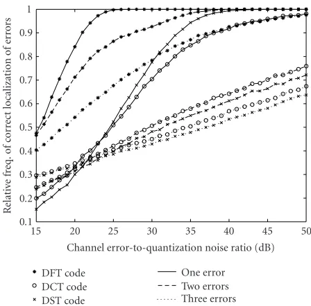
Figure 3shows the relative frequency of the correct
localiza-tion of errors assuming that the number of errors is estimated correctly. We observe that, in both steps, the frame expansion by the DFT code outperforms those by the DCT and the DST codes. When there is no quantization noise, the roots of the error locator polynomial for the DFT code are distinctNth roots of unity and they all lie on the unit circle. In the case of the DCT and the DST codes, the roots are all real and dis-tinct. When there is quantization, the roots for the DFT code lie about the unit circle whereas, in the case of the DCT and the DST codes, the roots can be real or complex conjugate pairs. Recall that the errors are localized by minimizing the absolute square of the estimated locator polynomial over the
1 0.9 0.8 0.7 0.6 0.5 0.4 0.3 0.2 0.1
R
elati
ve
fr
eq.
o
f
cor
re
ct
localization
of
er
ro
rs
15 20 25 30 35 40 45 50
Channel error-to-quantization noise ratio (dB) DFT code
DCT code DST code
One error Two errors Three errors
Figure3: Relative frequency of correct localization of errors at dif-ferent channel error-to-quantization noise ratios.
range of function f. It is easy to see that the roots for the DFT code have more degrees of freedom for perturbation than those for the DCT and the DST codes. Thus the DFT code is expected to result in better localization results.
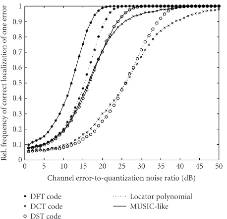
In the second step, we compared the error localization ef-ficiencies of the coding-theoretic and the subspace decoding approaches. The same Gauss-Markov source was expanded with the frames associated with the (18, 9) lowpass DFT, DCT, and DST codes. With a (18, 9)-BCH-like complex code, up to four errors can be corrected. Figures 4 and 5 show the relative frequency of correct localization of one and two errors, respectively. The performance improvement of the subspace algorithm over the locator polynomial approach is clear from the displayed figures. We have observed that the performance improvement decreases as the number of errors is increased. When the number of errors is equal to 4, the per-formances of the two approaches are similar. This is expected because, as the number of errors is increased, the dimension of the noise subspace is decreased, and when the number of errors is equal to 4, the noise subspace has dimension one. Higher noise subspace dimensionality provides greater de-grees of freedom and thus lesser perturbations for the noise subspace. The plots also show that the DFT code outper-forms both the DCT and the DST codes. The better perfor-mance of the DFT code is once again because of the similar reason as stated in the previous paragraph.
1 0.9 0.8 0.7 0.6 0.5 0.4 0.3 0.2 0.1 0
R
el.
fr
eq
uency
o
f
cor
re
ct
lo
calizat
ion
of
one
er
ror
0 5 10 15 20 25 30 35 40 45 50
Channel error-to-quantization noise ratio (dB) DFT code
DCT code DST code
Locator polynomial MUSIC-like
Figure4: Relative frequency of correct localization of one error at different channel error-to-quantization noise ratios.
encoded using 8 bits. This process was applied only to the lowest ten frequency coefficients of each block. The remain-ing frequency coefficients were quantized to zero. During the decoding, we assumed that the number of coefficient errors in a frame expansion was known.
Table 2 shows the PSNR of the reconstructed image at
different channel bit error rates (BERs) for both the coding-theoretic and the subspace-based error localizations. The re-sults are averaged over the same 20 channel realizations for the three frames. We observe that, at very low BERs, the per-formances of the three frames are similar. At higher BERs, the DFT frame performs better than both the DCT and the DST frames with coding-theoretic localization; however, when the errors are localized using the subspace approach, surpris-ingly, the DCT and the DST frames perform better than the DFT frame. This could happen perhaps because of the large quantization step size, which makes the error localization in-efficient for larger number of errors. Moreover, this is appro-priate to note here that, correct error localization does not necessarily lead to the least reconstruction error. The SNR of the reconstructed message depends on the number of the erroneous coefficients as well as their locations [4,8]. The performance improvement of the subspace approach over the coding-theoretic approach is evident from the two tables.
Figure 6displays the reconstructed images at BER 0.001 for
one channel realization. We observe that the quality of the reconstructed image is better with the subspace-based error localization.
7. CONCLUSION
In this paper, we have characterized a class of finite frames which can be considered for joint source-channel coding in cross-layer-enabled wireless communication environments.
1 0.9 0.8 0.7 0.6 0.5 0.4 0.3 0.2 0.1
R
el.
fr
equency
o
f
cor
re
ct
localization
of
tw
o
er
rors
0 5 10 15 20 25 30 35 40 45 50
Channel error-to-quantization noise ratio (dB) DFT code
DCT code DST code
Locator polynomial MUSIC-like
Figure5: Relative frequency of correct localization of two errors at different channel error-to-quantization noise ratios.
Table 2: PSNR for Lena image for different frames at different bit error rates. (a) Error localization by coding-theoretic approach. (b) Error localization by subspace approach.
(a)
BER 10−4 5×10⁻⁴ 10−3 5×10⁻³ 10−2
DFT31.89 31.60 31.17 24.59 19.27
DCT31.78 31.29 30.46 23.32 18.07
DST 31.86 31.48 30.87 23.43 18.06
(b)
BER 10−4 5×10⁻⁴ 10−3 5×10⁻³ 10−2
DFT31.90 31.83 31.50 26.43 20.45
DCT31.89 31.82 31.75 28.36 21.80
DST 31.90 31.88 31.81 28.64 21.92
(a)
(b)
Figure6: Reconstructed image with BER 0.001. (a) Error localization with coding-theoretic approach for DFT frame, DCT frame, and DST frame (from left to right). (b) Error localization with subspace approach for DFT frame, DCT frame, and DST frame (from left to right).
coefficient errors. Among the lowpass DFT, DCT, and DST frames, the DFT frame has the best performance with a Gauss-Markov source. When the subspace algorithm is ap-plied for image transmission, the DCT and DST frames are observed to perform better than the DFT frame at high BERs.
Utilization of frames for robust multimedia transmission is relatively new. In that context, this paper has considered only a class of frames and demonstrated their use in digital communication. It is now clear that all frames belonging to the same class do not result in the same reconstruction error even though they are all tight. Thus finding the best frames in the sense of minimum reconstruction error and numerical stability is an open issue. Further, this paper has considered only frames inCKandRK. Use of frames inl2(Z) for
correct-ing errors in message sequences is a much more challengcorrect-ing problem.
REFERENCES
[1] C. Bormann, C. Burmeister, M. Degermark, et al., “RObust Header Compression (ROHC): Framework and four profiles: RTP, UDP, ESP, and uncompressed,” IETF RFC 3095, July 2001.
[2] L.-A. Larzon, M. Degermark, and S. Pink, “The UDP-Lite Protocol,” IETF Internet Draft, December 2002, http:// www.itef.org/proceedings/03jul/I-D/draft-ietf-tsvwg-udp-lite-01.txt.
[3] A. C. Lozano, J. Kovaˇcevi´c, and M. Andrews, “Quantized frame expansions in a wireless environment,” inProc. Data Compression Conference (DCC ’02), pp. 232–241, Snowbird, Utah, USA, April 2002.
[4] V. K. Goyal, J. Kovaˇcevi´c, and J. A. Kelner, “Quantized frame expansions with erasures,” Applied and Computational Har-monic Analysis, vol. 10, no. 3, pp. 203–233, 2001.
[5] R. E. Blahut,Algebraic Methods for Signal Processing and Com-munications Coding, Springer-Verlag, New York, NY, USA, 1992.
[6] T. G. Marshall Jr., “Coding of real-number sequences for error correction: a digital signal processing problem,”IEEE Journal on Selected Areas in Communications, vol. 2, no. 2, pp. 381– 392, 1984.
[7] A. Gabay, P. Duhamel, and O. Rioul, “Spectral interpolation coder for impulse noise cancellation over a binary symmet-ric channel,” inProc. European Signal Processing Conference (EUSIPCO ’00), Tampere, Finland, September 2000. [8] G. Rath, X. Henocq, and C. Guillemot, “Application of DFT
codes for robustness to erasures,” inIEEE Global Telecommu-nications Conference (GLOBECOM ’01), pp. 1246–1250, San Antonio, Tex, USA, September 2001.
[9] J.-L. Wu and J. Shiu, “Real-valued error control coding by using DCT,” IEE Proceedings Part I: Communications, Speech and Vision, vol. 139, no. 2, pp. 133–139, 1992.
[10] S. Haykin, Adaptive Filter Theory, Prentice-Hall, Englewood Cliffs, NJ, USA, 1991.
[11] S. M. Kay, Modern Spectral Estimation: Theory and Applica-tion, Prentice-Hall, Englewood Cliffs, NJ, USA, 1988. [12] G. Rath and C. Guillemot, “Subspace algorithms for error
lo-calization with DFT codes,” inProc. IEEE Int. Conf. Acoustics, Speech, Signal Processing (ICASSP ’03), vol. 4, pp. 257–260, Hong Kong, China, April 2003.
[13] I. Daubechies, Ten Lectures on Wavelets, Society for In-dustrial and Applied Mathematics (SIAM), Philadelphia, Pa, USA, 1992.
[14] A. Gabay, P. Duhamel, and O. Rioul, “Real BCH codes as joint source channel codes for satellite image coding,” inProc. IEEE Global Telecommunications Conference (GLOBECOM ’00), pp. 820–824, San Francisco, Calif, USA, November–December 2000.
[16] M. R. Spiegel and J. Liu,Mathematical Handbook of Formulas and Tables, Schaum’s Outline Series. McGraw-Hill, New York, NY, USA, 2nd edition, 1998.
[17] R. E. Blahut, Theory and Practice of Error Control Codes, Addison-Wesley, Reading, Mass, USA, 1983.
[18] P. J. S. G. Ferreira and J. M. N. Vieira, “Locating and correct-ing errors in images,” inProc. 4th IEEE International Confer-ence on Image Processing (ICIP ’97), vol. 1, pp. 691–694, Santa Barbara, Calif, USA, October 1997.
Gagan Rath received the B.Tech. degree in electronics and electrical communica-tion engineering from the Indian Institute of Technology Kharagpur in 1990, and the M.E. and Ph.D. degrees in electrical com-munication engineering from the Indian Institute of Science, Bangalore, in 1993 and 1999. He is currently working as a Research Scientist at INRIA, France. His research in-terests are in broadly digital signal process-ing and communications.
Christine Guillemotis currently “Directeur de Recherche” at INRIA, in charge of a re-search group dealing with image modelling, processing, and video communication. She holds a Ph.D. degree from ENST ( ´Ecole Nationale Sup´erieure des T´el´ecommuni-cations), Paris. From 1985 to October 1997, she was with France Telecom/CNET, where she was involved in various projects in the domain of coding for TV, HDTV, and