R E S E A R C H
Open Access
Reliability-aware iterative detection scheme
(RAID) for distributed IDM space-time codes in
relay systems
Florian Lenkeit
*, Dirk Wübben and Armin Dekorsy
Abstract
In this article, distributed interleave-division multiplexing space-time codes (dIDM-STCs) are applied for multi-user two-hop decode-and-forward (DF) relay networks. In case of decoding errors at the relays which propagate to the destination, severe performance degradations can occur as the original detection scheme for common IDM-STCs does not take any reliability information about the first hop into account. Here, a novel reliability-aware iterative detection scheme (RAID) for dIDM-STCs is proposed. This new detection scheme takes the decoding reliability of the relays for each user into account for the detection at the destination. Performance evaluations show that the
proposed RAID scheme clearly outperforms the original detection scheme and that in certain scenarios even a better performance than for adaptive relaying schemes can be achieved.
1 Introduction
During the last decade, cooperative communications and especially relaying has been a promising and constantly growing field of research. While, in the first place, the main purpose for introducing relays into wireless commu-nication systems was the reduction of path losses between communicating nodes, relay systems also offer spatial diversity and, therefore, allow for the adoption of diversity exploiting techniques known from multi-antenna (Multi-ple Input - Multi(Multi-ple Output, MIMO) systems. MIMO sys-tems have been shown to allow for a significantly higher performance in terms of throughput or robustness against fading than their single-antenna counterparts, which is mainly due to the exploitation of space for further degrees of freedom in addition to time and frequency [1,2].
In this study, we consider a two-hop relaying system in which multiple sources transmit to one destination via a number of parallel relays. In such a system, the distributed relays can be grouped into a so-called Virtual Antenna Array (VAA), which can then be used to jointly process data, exploiting receive or transmit diversity [3]. Due to the distributed fashion of the VAA it can not be assumed that all nodes within the VAA can exchange arbitrarily
*Correspondence: [email protected]
Department of Communications Engineering, University of Bremen, Bremen, Germany
much information as this would severely increase the sig-naling overhead and subsequently decrease the overall throughput. Hence, it is not possible to achieve perfect receive cooperation among all nodes within the VAA with justifiable effort. However, since the focus of this study is on the exploitation of transmit diversity, no receive cooperation at all is assumed and, thus, signaling among the relays is avoided. This means that each relay might estimate the source information differently. Furthermore, besides the limited exchange of information, it is also a challenging task to keep all nodes perfectly synchronous in terms of timing and frequency. Asynchronism among the nodes of the VAA or, in general, among different VAAs can lead to severe performance degradations for transmis-sion schemes which require strict orthogonality among the transmitting nodes.
One of the most prominent transmit cooperation tech-niques applied to VAAs is Time Coding. Space-Time Coding evolved in the context of MIMO systems and is a very efficient transmit diversity exploiting strat-egy if no Channel State Information (CSI) is available at the transmitter [4,5]. The idea behind Space-Time Coding is to exploit space and time as two dimensions for coding. The first applications of Space-Time Codes (STCs) to relaying systems was done in [6] and later in [7]. Since these approaches were direct adoptions of
Alamouti’s scheme and its corresponding generalization, they principally require perfect orthogonality among the relay signals. In [8,9] a STC approach based on the non-orthogonal multiple access scheme Interleave-Division Multiple Access (IDMA) [10] has been presented. This Interleave-Division Multiplexing Space-Time Code (IDM-STC) does not require any synchronization among the transmit antennas which makes it a promising technique for relay systems. Consequently, the IDM-STC has been applied to relay systems in a distributed fashion using uncoded transmission and the Decode-and-Forward (DF) relaying protocol [11]. In [12], the principles of distributed IDM-STCs (dIDM-STCs) have been extended to coded systems and further relay protocols like Amplify-and-Forward (AF) and Decode-Estimate-and-Amplify-and-Forward (DEF). It has been shown, that the dIDM-STC is in fact a good choice for relaying systems due to its flexibility regarding code rate and number of transmitting nodes and due to its robustness against asynchronisms. However, it was also pointed out that non-perfect decoding at the relays has to be taken into account at the destination as it leads to error propagation, which is a general problem of DF since it can severely degrade the overall performance.
One possibility to deal with erroneous decoding at the relays is to adaptively select only those relays to for-ward to the destination which have decoded correctly [7]. However, since erroneous relays may still contribute to the transmission, it does not seem reasonable to dis-card erroneously decoded messages. Instead, all relays should forward to the destination and the detector should handle the correct as well as the erroneous messages prop-erly. In [13] a detector for uncoded DF was presented which applies a weighting of the relay messages accord-ing to the reliability of the whole source-relay-destination link. For that, all S-R-D links were modeled by equiv-alent Gaussian channels whose SNRs are dependent on the bit error probabilities on both hops. The messages over different S-R-D links were then weighted according to the respective equivalent SNR and finally combined. In [14,15] distributed turbo codes in DF systems were investigated. In these studies, the first hop transmission was modeled using a Binary Symmetric Channel (BSC) with a crossover probability dependent on the first hop transmission quality, i.e., the bit error probability at the relay. The BSC model was then used in order to weight the exchanged information between the two constituent decoders at the destination. In [16] we presented a modi-fied detection strategy for dIDM-STC, adopting the ideas from [13,14] and incorporating the decoding reliability of the relays into the detection at the destination. This was achieved by estimating the decoding reliabilities at the relays and signaling this information to the destination. The reliability information of all relays was then used for a weighted combining of the relay messages. As a result, a
significant performance improvement was achieved com-pared to the common detection scheme for dIDM-STC from [12]. However, it could also be seen that the actual usage of the available information at the destination was not yet optimal as the results indicated a performance gap compared to adaptive relaying schemes in which only correct relays forward to the destination.
In this article, we present a novel Reliability-Aware Iter-ative Detection scheme (RAID) for distributed IDM-STCs in Decode-and-Forward relay systems. The main idea of this scheme is to distinguish between the detection of the relay messages and the subsequent estimation of the source messages. First, a grouping of the relays is intro-duced and the relays are separated by their decoding success. While the signals from the successful relays are combined and jointly decoded, as for the common detec-tor, the signals from the erroneous relays are all processed separately. The goal here is to firstly estimate the relay messages as good as possible. This approach is different to [16] where all relay signals were combined during the iterative detection, directly estimating the source infor-mation. After the final iteration of the iterative detection process, the estimates of the messages of the correct relays and the estimates of the messages of the erroneous relays are combined using a weighting operation simi-lar to [16] in order to estimate the source messages. In contrast to [16], here the weighting is carried out after the iterative detection process, i.e., after firstly estimating the relay messages. While first ideas of this new detec-tion scheme have been presented in [17], here the RAID scheme is extended to the multi-user case. We present more detailed derivations as in [17] and also give much further insight especially into the determination of the error probabilities at the relays. We will show that esti-mating the error probabilities in a practical system leads to almost no performance loss compared to a perfect knowledge. Moreover, extensive comparisons with other detection schemes like the common detection scheme or the adaptive scheme are given and discussed for single-user as well as for multi-single-user systems. As will be shown, the proposed RAID scheme achieves significant perfor-mance improvements compared to the common detection and to the strategy in [16]. It even performs better than the adaptive relaying scheme in certain scenarios, as it also exploits information from erroneous relays which is not the case for the adaptive scheme.
for the formulation of the new detector. Then, the new RAID scheme is presented in detail. In Section 5 numeri-cal results are given and the RAID scheme is compared to the conventional IDM-STC detection scheme as well as to an adaptive scheme. In Section 6, finally, some conclusions are drawn.
The nomenclature for this article is as
fol-lows. Scalars are denoted by small letters a,
while column vectors are denoted by bold letters a = [a1. . .aN]T and matrices by bold capital letters A = a1,1 . . .a1,N; . . .;aM,1 . . .aM,N
. Interleaved sequences are denoted by a dasha’ and double interleaved sequences by two dashesa”. Log-likelihood-ratios (LLRs) of scalaraand of elements of a vectoraare denoted by
a = log
Pr{a=0}
Pr{a=1}
anda =
a1,. . .,aN
, respec-tively. The expectation of a random processXis expressed as E{X}and its variance asσX2. The L2-norm of a vectora is denoted byaandF2is the gallois field GF(2).
2 System model
2.1 Overview
A two-hop relay system as depicted in Figure 1 is consid-ered. Multiple sourcesSm, 1 ≤ m ≤ M, communicate with one common destination D via N parallel relays
Rn, 1 ≤ n ≤ N performing Decode-and-Forward. No direct links from sources to destination are assumed and the discrete-time channel impulse responses fromSm to Rnand fromRntoDare given byhm,nandgn, respectively. Frequency-selective block Rayleigh fading channelsh˜m,n andg˜nwithLhandLgi.i.d channel taps are assumed and the path loss on each hop is given bydsuch that
hm,n=d−
2h˜m,n (1a)
gn=d−
2g˜n, (1b)
where d denotes the distance between the correspond-ing nodes and is the path loss exponent. The channel
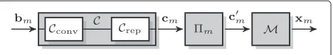
Figure 2Structure of sourceSm: common IDMA transmitter
structure consisting of channel encoderC, interleavermand
symbol mapperM.
impulse responses are normalized such that the total received power depends only on the path loss but not on
Lh andLg, respectively, i.e., E{˜hm,n2} = E{˜gn2} = 1. Also, each receiver, i.e., Rn and D experiences addi-tive white gaussian noise (AWGN) of powerσn2. Due to the half-duplex constraint, the transmission time can be divided into a source-relay phase in which the sources broadcast their information to the relays and a relay-destination phasein which the relays simultaneously for-ward the processed information of all sources to the destination. Both phases are described in detail in the subsequent paragraphs.
2.2 Source-relay phase
In the first phase, the sources simultaneously broad-cast their information to the relays applying IDMA [10]. Figure 2 shows the transmitter structure of the source
Sm, where the binary information sequencebm ∈ FL2b of lengthLbis encoded by a codeCof rateRc=Rc,conv·Rc,rep consisting of a serial concatenation of a convolutional codeCconvof rateRc,convand a repetition codeCrepof rate
Rc,rep. The resulting coded sequencecm ∈ FL2c of length
Lcis interleaved by a user specific interleaverm result-ing in the interleaved code sequencecm∈FLc
2. Finally, the interleaved code bits are mapped onto symbols from the normalized alphabetAresulting in the transmit sequence xm ∈ALx of lengthLxwithσx2 = 1. The symbolsxmare then broadcasted to all relays.
Figure 1Topology of the considered multi-user two-hop relay system.SourcesSmand relaysRnare distributed equidistantly with spacingsdS
The received signalynat relayRnis given by the super-position of all source signalsxmconvolved with the cor-responding channel impulse responseshm,nplus additive white gaussian noisenn∈CLx+Lh−1of powerσn2as First, in order to separate the user signals xm, IDMA multi-user detection (MUD) is performed using the itera-tive soft-RAKE algorithm [10]. Since for soft-RAKE detec-tion all multipath propagadetec-tions of each signal xm are resolved separately, in total M·Lh different layers have to be resolved at each relay. As a useful measure for later investigations, the load on the first hopβSRis introduced. To account for the separate detection of all multipath propagations by the soft-RAKE detection, it is defined here in terms of layers as
βSR=M·Lh·Rc. (3)
By this definition, the load is not only dependent on the number of usersMand the overall code rateRc, but also on the number of channel tapsLh, i.e., the degree of frequency selectivity of the channel. An alternative to soft-RAKE detection is multi-layer APP detection [18], which avoids gaussian approximation of multi-user interference and, hence, allows for higher bandwidth efficiencies. But since the complexity of multi-layer APP detection grows exponentially with the number of usersMand the num-ber of channel tapsLh, i.e.,O
2MLh, it is not suited for the
investigated system.
The MUD at relayRn delivers LLRsRbnm for the user information wordsbm. After hard decision, the estimates
ˆ
form the relay information wordsbm,nas
ˆ
bRn
m →bm,n, (4)
where bm,n denotes the relay message at relay Rn with respect to source Sm. Note that due to decoding errors
at the relay, the information wordsbmandbm,nmight be different from each other. To cope with this problem, the following strategies are possible:
• Decoding errors at the relays are not detected and the decoding at the relays is assumed to be perfect. Subsequently, allM relay messagesbm,nof relayRn are forwarded to the destination. This is done for the common dIDM-STC detection.
• Decoding errors are detected by exploiting a cyclic redundancy check (CRC) code and only correct information words, i.e.,bm,n=bm, are forwarded to the destination. This is done for adaptive relaying which is discussed in more detail in Section 3.2. • The decoding error probability at the relays is
estimated, e.g., as described in Section 4.1, and the transmit power for the relay messages is adjusted according to the decoding error probability at the corresponding relay. That means, the higher the error probability at the relay, the lower the corresponding transmit power. This is done for adaptive relaying with power allocation. This scheme is not considered further in this study, as it basically has the same problems as the common dIDM-STC detection scheme, which are described in Section 3.1. • Decoding errors are detected as for the adaptive
relaying scheme. However, in contrast to the adaptive scheme, erroneous decoding at the relays is handled by the detector at the destination and not by the relays. Hence, allM information wordsbm,nare transmitted with the same power to the destination, regardless of the decoding success. Additionally, the outcomes of the CRC checks w.r.t. the sourcesSmare signaled to the destination where they are used later on by the new proposed detection scheme.
For non-adaptive relaying, all relay information words bm,n are encoded using the same channel code C as the sources and interleaved by the user specific inter-leaversm. In addition to the user specific interleaving, the sequences cm,n are additionally interleaved using a relay specific interleaver r,n, such that a unique inter-leaver tuple m;r,n is assigned to each of the M · N interleaved sequencescm,n across all N relays. These
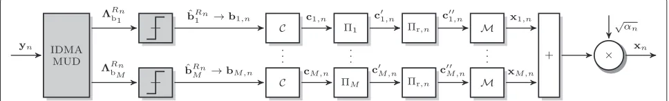
Figure 3Structure of relayRnconsisting of IDMA multi-user detection (MUD) andMparallel IDMA encoding branches each containing a
interleaved sequences are mapped onto symbols from the same alphabet A and summed up. Finally, a scaling by √α
n = M1 ensuresσx2n = 1 independent of the number
of supported usersM, resulting in the relay transmit signal
xn=√αn relays are broadcasted simultaneously to the destination
D. Under the assumption of perfect decoding at all relays, each user message bm is transmitted from all N relays and a distributed IDM-STC is formed across theNrelays. The receive signal y at the destination consists of the superposition of the relay signalsxn convolved with the corresponding channel impulse responsesgnplus additive white gaussian noisen∈CLx+Lg−1as gn. Again, for later investigations the load on the second hop is defined similar to (3) as
βRD=M·N·Lg·Rc. (7)
Hence, under the assumption of equally long channel impulse responses on both hops, the load on the second hop isN times as large as on the first hop, i.e.,βRD = N·βSR.
3 Common detection schemes
3.1 Common IDM-STC detector
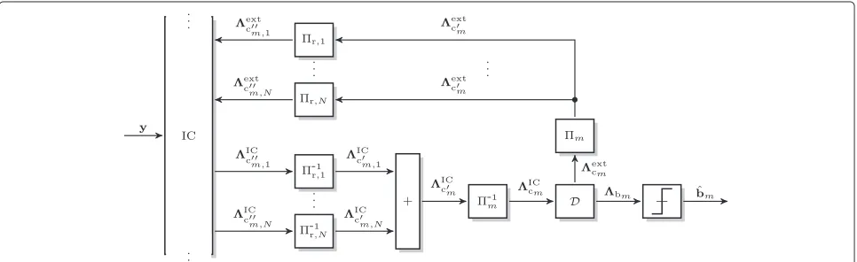
In order to separate allM·Nlayersxm,nat the destination, an iterative turbo detection is applied [8]. Figure 4 depicts
the part of the overall detector for the detection of mes-sagebmof sourceSm. After soft-RAKE based interference cancelation (IC) with respect to allM·Nlayers, relay spe-cific interleaving is reversed-1r,n, yielding the LLRsICc
m,n.
Since the relays transmitted over statistically independent channelsgn, the LLRs ICcm,n represent statistically
inde-pendent observations ofcm and, hence, are summed up.
ICc
This de-interleaving and the subsequent summation (8) can be interpreted as the actual decoding of the dIDM-STC. The sum signalICc
mis then de-interleaved using the
user specific interleaver-1m, such that the de-interleaved LLRs forcmare given by
m, soft-input soft-output channel decodingD
is performed. The decoding consists of the decoding of the repetition codeCrepwhich is a summation of the cor-responding LLRs, followed by the decoding of the convo-lutional codeCconvusing the well-known BCJR algorithm [19]. The BCJR delivers LLRsbmfor the information bits bm as well as LLRscm for the code bitscm. In order to
obtain the extrinsic information generated by the decoder, the input LLRsICc
mare subtracted from the output LLRs,
yielding
extc
m =cm−
IC
cm. (10)
The extrinsic informationextc
m is then re-interleaved by
the user specific interleaver m followed by the corre-sponding relay specific interleaversr,nand fed back as a-priori information to the IC. At the same time, the LLRs
bm of the information bitsbmare hard quantized,
lead-ing to the hard estimates bˆm = Q
bm. This iterative process is repeated until the CRC check ofbˆm is correct or the maximum number of iterationsNitis reached.
3.1.1 Issues
The major issue of the common detection scheme is that no information regarding the quality of the first hop trans-mission and the reliability of the decoding at the relays is taken into account. In contrast, it is inherently assumed that all detections at the relays are perfect, i.e.,bm,n=bm, such that the first hop can be neglected for detection at the destination. Clearly, this assumption is not valid in prac-tical systems as fading and noise lead to decoding errors at the relays which then propagate to the destination. The actual problems of the common detector with respect to erroneous decoding at the relays are twofold:
• The summation (9) of the de-interleaved LLRs is dominated by the strongest LLRsICc
m,n. This is
especially a problem if one or more relays experience a weak channel on the first hop and a strong channel on the second hop, because the LLRsICc
m,nonly
depend on the quality of the second hop but not on the first hop. Due to the weak first hop these relays are very likely to generate errors due to erroneous decoding. However, at the same time these relays dominate other relays with a weaker second hop which may have decoded correctly.
• The second issue is the loss of information about the individual relay signalsxndue to the summation (9) and the subsequent joint decoding. The extrinsic informationextc
m generated by the decoder is used as
a-priori information for the next detection iteration for all relays. Thus, it is implicitly assumed that all relays transmitted the same codeword. If this is not the case, the feedback to the IC and the actual observationsyare contradictory and the feedback may even degrade the performance of the IC. Hence, regarding the IC, it would be favorable to process each relay separately during the iterative detection.
3.2 Adaptive relaying
One possibility to overcome the aforementioned prob-lems is to adaptively select only the correctly decoded messages at each relay to be forwarded to the destination while all erroneously decoded messages are not transmit-ted [7]. That means, relayRnforwards only the messages of sourcesSmwhich were decoded correctly. The advan-tage of this strategy is that the common IDM-STC detection scheme could be applied with only marginal modifications to the system, e.g., the cyclic redundancy check (CRC) code has to be exploited by the relays in
order to determine the decoding success and to adaptively select only the correctly decoded messages.
However, even erroneous relays may contribute to the overall transmission as their relay information wordsbm,n, depending on the number of erroneous bits, may still be highly correlated to the source information words bm. Therefore, it seems not reasonable to discard erroneously decoded messages but to forward them anyway and let the destination handle the correct as well as the erroneous messages properly. Such a detection scheme is presented in the next section.
4 Reliability-aware iterative detection (RAID) In order to consider decoding errors at the relays within the detector at the destination, a suitable model describing the overall transmission including the decoding reliabil-ities of the relays is required. On the one hand, this model should be accurate enough to actually improve the detection at the destination, on the other hand it should be simple enough to avoid an excessive increase in the complexity of the detector or in the signaling overhead.
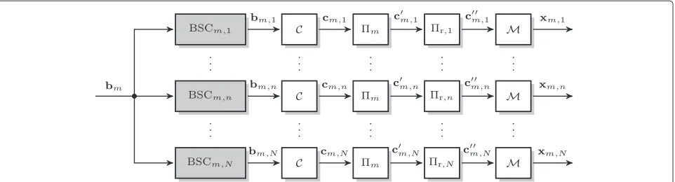
4.1 Equivalent transmission model for 1st hop transmission
Based on the ideas presented in [14,15], decoding errors at the relays can be described using binary symmetric chan-nels (BSCs) with a certain crossover probability. Accord-ing to this description, the relay information wordbm,nin (4) is modeled as at relay Rn regarding the source information word bm. This crossover probability is zero for perfect decoding at the relay and increases as the relay’s decoding reliability decreases. Using this description, an equivalent transmis-sion model for the transmistransmis-sion from the sources over the first hop to the relays, including decoding at the relays, can be derived. Figure 5 depicts such an equivalent joint model for the transmission ofbmvia the relaysR1up to
Figure 5Equivalent transmission model for transmission ofbmfromSmviaR1up toRNtoD.The shaded BSC blocks represent the shaded blocks from Figures 2 and 3.
information bits generated by the MUD at the relay is possible [20]. Denoting this estimateqˆm,n, it holds
ˆ qm,n=E
1
1+e|Rnbm|
≈ 1
Lb Lb
i=1 1
1+e|Rnbm,i|
, (13)
where the expectation can be approximated by the time average due to the ergodic theorem. Note thatqˆm,n = 0 even if the decoding at the relay was correct. Hence, in case of successful decoding at the relay ACK is signaled to the destination, while unsuccessful decoding leads to the signaling of a NAK in form of qˆm,n. The principle of this signaling is depicted in Figure 6, where CRCm,n denotes the CRC check at relay Rn regardingbm. For a more detailed discussion of the signaling refer to [16].
4.2 RAID scheme
Based on the presented equivalent transmission model, the new RAID is proposed. This detection scheme takes the decoding success (CRCm,n=ACK/NAK) of the relays as well as the error probabilitiesqˆm,ninto account in order to improve the detection quality compared to the com-mon detection scheme discussed in Section 3.1. In the following, the components of the RAID scheme, i.e., the relay grouping, the detection process and the weighted combining are discussed in detail.
4.2.1 Relay grouping
To address the second issue of the common detection strategy, i.e., the loss of information about the individual
relay signals xm,n, a user specific separation of the cor-rect relays and all erroneous relays is introduced. Since all correct relays have transmitted the same code word cm,n=cm, their LLRs can be combined after relay specific de-interleaving. All erroneous relays, however, may have transmitted pairwise different code words and, hence, are all processed separately.
Based on the decoding success (CRCm,n = ACK/NAK) with respect to one specific source Sm, each relay Rn is assigned to one of two disjoint groups, the group of relays which have correctly decoded the source message, i.e., bm,n = bm, and the group of relays which have not cor-rectly decoded the source message, i.e.,bm,n =bm. For the sake of notational simplicity, the setRmof indices of the correct relays w.r.t. sourceSmand the setR¯mof indices of erroneous relays w.r.t. sourceSmare introduced
Rm= {n|qm,n=0, 1≤n≤N} (14a)
¯
Rm= {n|qm,n =0, 1≤n≤N}. (14b)
Obviously, the union of both sets is the set of the indices of all relays, i.e.,Rm∪ ¯Rm = {1 ,. . .,N}. Furthermore, two indexing functionsρmandρ¯mare defined, such that
Rm= {ρm(1),. . .,ρm(Im)}, Im= |Rm| (15) ¯
Rm= { ¯ρm(1),. . .,ρ¯m(Km)}, Km= | ¯Rm| (16)
with ρm(1) < ρm(2) < · · · < ρm(Im) and ρ¯m(1) < ¯
ρm(2) <· · · < ρ¯m(Km). This meansρm(1)up toρm(Im) represent the Im indices of the correct relays w.r.t Sm
andρ¯m(1)up toρ¯m(Km)represent theKm indices of the erroneous relays w.r.tSm, i.e.,
bm,ρm(i) =bm, 1≤i≤Im (17a) bm,ρ¯m(k) =bm, 1≤k≤Km. (17b)
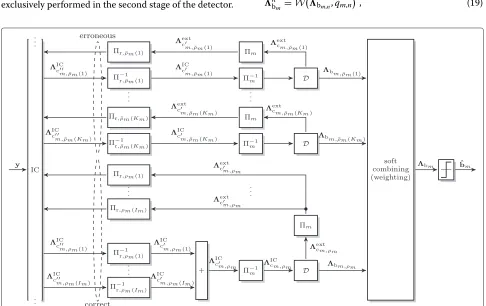
Figure 7 shows the part of the overall proposed detec-tor which is relevant to the detection of bm. The LLRs from the IC are grouped based on the decoding suc-cess (ACK/NAK) at the relays. Since the correct relays have transmitted the same code wordcm, their LLRs are summed up after relay specific de-interleaving, similar to the common detection scheme, i.e.,
ICc
m,ρm =
Im
i=1
-1r,ρ
m(i)
ICc
m,ρm(i)
, (18)
and are then jointly de-interleaved by the user specific interleaver and jointly decoded (bottom part). The erro-neous relays, however, have transmitted different code words and are, therefore, processed and decoded sepa-rately (top part). The goal of this first stage of the detection is the best possible estimation of the relay information words bm,n and not of the source information words bm. The estimation of the source information words is exclusively performed in the second stage of the detector.
Finally, after the last iteration, theKm +1 decodersD deliver LLRsbm,ρm for the information words of the
cor-rect relays and LLRsbm,ρ(¯k)for theKminformation words of the erroneous relays. The explicit decoding, hard deci-sion and subsequent re-encoding at the relays ensures that all relays actually transmitted a valid code word which is fundamental for the validity of the joint equivalent transmission model.
4.2.2 Weighted combining
Based on the estimates for the relay information words bm,n, now an overall estimate for the source information wordbmshould be determined. This estimate should not only include the LLRs from the correct relays, but also the LLRs from the erroneous relays as, depending on the error probabilitiesqˆm,n, the relay information of the erroneous relays is still correlated to the source information.
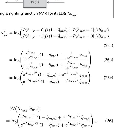
The question arises, how to obtain an estimatenb
mfor
the source informationbm given the estimatebm,nfor a
specific relay information wordbm,nand the correspond-ing error probabilityqˆm,n. How does the BSC modeling of the first hop transmission translate to the LLRs for the relay information word and the source information word? Figure 8 illustrates this relationship, where the function W(·)needs to be found, such that
nb
m =W
bm,n,qˆm,n
, (19)
Figure 8BSC modeling of relay information wordbm,nand corresponding weighting functionW(·)for its LLRsbm,n.
withnb
mdenoting the estimate for the source information bmtaking only relayRninto account. In order to find this function, the estimatenb
mfor an arbitrary elementbmof bmis written as
By using the law of total probabilities [21], the probabil-ities of the source informationbmcan be written w.r.t. the probabilities of the relay informationbm,nas
P(bm=0|y)=P(bm=0|bm,n=0,y)P(bm,n=0|y)
The probabilities ofbmgivenbm,nsolely depend on the crossover probabilityqˆm,nof the BSC,
P(bm=0|bm,n=0)=P(bm=1|bm,n=1)
=1− ˆqm,n (22a)
P(bm=1|bm,n=0)=P(bm=0|bm,n=1)
= ˆqm,n, (22b)
such that the estimate nb
m can be rewritten as (25a).
Expressing the probabilities by LLRs [22]
P(bm,n=0|y)=
leads to (25b) and after some algebraic manipulations to (25c). Thus, the desired functionW(·)is finally found to be
is a shorthand notation for applying (25c) to every element ofbm,n.
In (25c) the error probabilityqˆm,nof the BSC obviously leads to a weighting of the estimates of the relay infor-mation word given bybm,n. For completely uncorrelated bm,n andbm, i.e., qˆm,n = 0.5, the relay transmitted no information regardingbmand, hence,nbm =0. However,
asqˆm,ndecreases,bnmtends tobm,ngiving an estimate of bmwith respect to the information from relayRn.
Since all transmit channels are statistically indepen-dent, the observations from all relays can be summed up resulting in the estimate rect relays. Finally, hard quantization leads to the overall estimatebˆm=Q
bm
for the source messagebm.
4.3 Pseudo code
In order to facilitate the comprehension of the proposed RAID scheme, a pseudo code for the overall detection process is given in Algorithm 1. The algorithm requires the set of all CRC check resultsCRCm,n
, the set of all error probabilitiesqˆm,n
responses from the relays to the destinationgn
, the sets of all relay specific and user specific interleaversr,n
and{n}and the noise varianceσn2.
After the grouping, as described in Section 4.2.1 (lines 3–14), the iterative detection process is performed (lines 15–35). Besides some interleaving and de-interleaving operations, it mainly consists of the softRAKE detection (line 18), the combining of the information from the cor-rect relays (line 22) and the APP-decoding (lines 27–28). Finally, after the detection, the weighting (line 37) and combining (line 39), as described in Section 4.2.2, is per-formed. The hard decision (line 41) leads to the hard estimates of the user information wordsbˆm.
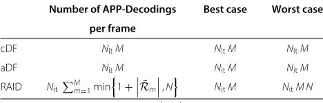
4.4 Computational complexity
The computational complexity of the presented detection schemes, i.e., cDF, aDF, and RAID, mainly differs in the number of APP-decodings per frame. Hence, the number of APP-decodings per frame is a useful measure in order the compare the complexity of the schemes. Table 1 gives an overview of the number of decodings per frame. As can be seen, for cDF and aDF one APP-decoding per user, frame and iteration is required, independent of the num-ber of successful relays. For RAID, however, the numnum-ber of APP-decodings depends on the number of successful relays. In the best case, i.e., all relays were successful, only one decoding operation per iteration and user is required, leading to the same complexity as cDF and aDF. In the worst case, every relay message is decoded separately, resulting in a complexityNtimes as high as for cDF and aDF. Note that the aDF scheme would fail in the worst case scenario, while cDF and RAID might still achieve correct decoding.
5 Numerical results
For numerical investigations, a two-hop relay system with
MsourcesSm,N =4 parallel relaysRnand one common destinationDas depicted in Figure 1 is considered. The distance between the central source and the destination is normalized todSD = 1 and the inter-relay distance is set sodR = 0.2. Frequency-selective block Rayleigh fad-ing withL = Lh = Lg i.i.d. channel taps is assumed on
Table 1 Comparison of the computational complexity of cDF, aDF, and RAID
Number of APP-Decodings Best case Worst case
per frame SmandNitnumber of iterations per frame.
both hops and the path loss exponent is set to = 3. For channel coding, a combination of the non-recursive half-rate(5, 7)8convolutional code and a repetition code of rateRc,repis applied and the codeword length is set to
Lc=1024 codebits. The QPSK alphabetAwithσx2=1 is chosen and the relay transmit signals are normalized such thatσx2n = 1 regardless of the number of supported users
M. That way, all schemes have the same power cost for a given number of usersM, making the comparisons fair. For detection at the relays and at the destinationNit=10 iterations are performed. Initially, the error probabilities
qm,nare assumed to be perfectly known at the destination.
5.1 Single user
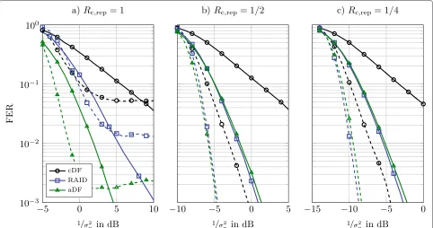
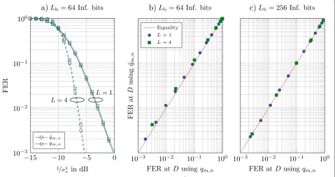
First, a single user system is considered, i.e., M = 1. Figure 9 depicts the frame error rate (FER) at the desti-nation for the common detection scheme (cDF) and the proposed RAID scheme for different code ratesRc,repover flat (L=1, solid) and frequency selective channels (L=4, dashed). As reference, also the adaptive relay system is given (aDF). Starting with the system without repetition coding, i.e., Rc,rep = 1, it can be seen, that the RAID scheme clearly outperforms the common scheme for flat, as well as for frequency selective channels. The adaptive scheme, however, performs significantly better than the RAID scheme. Also, all three detection schemes lead to an error floor for frequency selective channels.
Since soft-RAKE-detection is applied, overallN·Llayers have to be separated at the destination. In case ofL = 4 this corresponds to a load of βRD = 8. Hence, in this scenario, the system is eight times overloaded. Clearly, a separation of all layers fails at this high load even for high signal-to-noise ratios (SNRs) resulting in the observed error floor. Even for flat fading the system is significantly overloaded, i.e.,βRD=2. In this case, the adaptive scheme outperforms the RAID scheme, since the system is inter-ference limited and adaptively switching erroneous relays off decreases the load and leads to a better separation of the layers at the destination.
Figure 9FER at the destination for common detection, RAID and adaptive relaying and different coderatesRc,repof the repetition code. M=1 user. Solid:L=1 channel taps, dashed:L=4 channel taps.
Further decreasing the code rate of the repetition code to Rc,rep = 14, as in Figure 9c, reduces the load to
βRD = 12for flat fading andβRD =2 for frequency selec-tive fading. Since the system is not interference limited anymore, this results in a better performance for RAID compared to the adaptive scheme even for the frequency selective case.
In Figure 10, the corresponding end-to-end throughput
η, assuming a selective repeat automatic repeat request (ARQ) protocol, is shown. For the given system parame-ters, i.e., QPSK modulation and a half-rate convolutional code, it reads
η=log2(|A|)·Rc,conv·Rc,rep·(1−FER)
=Rc,rep·(1−FER) , (29)
where |A| denotes the cardinality ofA. While the sys-tem without repetition coding clearly leads to the worst performance in terms of FER for all three schemes, it outperforms the other systems in terms of throughput above approx. σ12
n = −5 dB for aDF and
1 σ2
n = −3 dB to
1 σ2
n = −2 dB for RAID and cDF. In the high SNR region the
throughput clearly tends to the spectral efficiency Rc,rep of the system. Interestingly, for Rc,rep = 1 and L = 4
the common scheme achieves a higher throughput than RAID up to 1
σ2
n = −1dB. Again, the reason for this
behav-ior is the high load in the system and the very low SNR per layer the detector experiences at this point. The LLRs delivered by the IC are, hence, very small. In this case, it is better to add all available LLRs up, trying to increase the signal level and achieve successful joint decoding than to separate the layers according to the decoding success of the relays and thereby keeping the signal levels low. Above
1 σ2
n = −1 dB, the signal levels are sufficiently high and
the RAID outperforms the common scheme. The same behavior can be seen forRc,rep = 12 andL = 4 but with much smaller characteristic. This is due to the decoding of the repetition code, which corresponds to the summa-tion of two subsequent LLRs. The signal levels after IC are hereby increased sufficiently and the RAID achieves almost the same performance as cDF in the lower SNR region up to approx. 1
σ2
n = −8 dB. Above this SNR, again
RAID clearly outperforms cDF. Finally, for Rc,rep = 14 RAID always performs better than cDF, as the observed behavior is completely avoided for higher code rates
Rc,rep.
5.2 Estimation of error probabilityqm,n
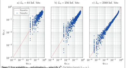
While the previously shown results for the RAID scheme were all based on perfect knowledge ofqm,n, subsequently the impact of the usage of its estimationqˆm,ngiven in (13) is investigated. Figure 11 shows samples of the bit error probabilityqm,n and its estimateqˆm,nfor different frame
sizes Lb in a double logarithmic representation. These samples were obtained by Monte Carlo simulations, i.e., for transmissions at varying SNR the resultingqm,n and the correspondingqˆm,n were calculated and plotted. The solid line indicates equality, while a mark above the line means a too high and a mark below the line a too low esti-mate. First, in the plots the quantized nature ofqm,ncan be seen. Since only integer numbers of erroneous bits can occur,qm,nis limited to the valuesL1b,L2b,. . .. ForLb=64, e.g., this is 0.0156, 0.0312,. . ., which corresponds to the marks in the plot. Clearly, for larger frame lengths Lb, lower error probabilities are possible, e.g., 2561 = 0.0039 forLb = 256 and 25601 = 0.004 forLb = 2560. In addi-tion, the size of the quantization steps gets smaller, as it is also given by L1
b. On the other hand, the estimate qˆm,n
is continuously distributed as the LLRsRn
bm the estimate
is based on, are continuously distributed.
Apparently, also the quality of the estimate strongly depends on the frame size. While for a frame size of
Lb=64 information bits the estimate already significantly deviates from the true value for error rates of 10−1, the estimate improves for larger frame lengths. The reason for this behavior is the approximation in (13). Since the expectation can only be estimated using the mean over all LLRs within one frame, the estimate clearly improves as the frame length increases.
Another interesting observation is the behavior of the estimatesqˆm,nfor small error probabilities. The lower the error probabilityqm,nis, the stronger deviates the estimate
Figure 11Error probabilityqm,nand estimationqˆm,nusing LLRsRbmn.Flat fading channels.Rc,rep=
ˆ
qm,n fromqm,n. Again, the reason for this is the approxi-mation in (13). Strictly speaking, the expectation has to be calculated with respect to the overall distribution ofRn
bm,
i.e., all events which lead to one specificqm,nneed to be taken into account in order to obtain a valid estimation. However, since only one frame with a specific channel realization is available at the relay, the influences of the channel are neglected in the approximation of the esti-mate, leading to the observed deviation for single events. Clearly, this is also true for larger error ratesqm,n. How-ever, due to the logarithmic representation, the relative deviation is much smaller.
Finally, it can be seen from Figure 11, that for very high error probabilities, (13) leads to an underestimation, while for lower error probabilitiesqm,nis slightly overestimated. This leads to an overall more conservative behavior of the system due to the weighting (27).
In Figure 12, the achieved FERs at the destination using RAID withqm,n or its estimateqˆm,n are depicted. Figure 12a) shows the FERs for both cases for flat (L =
1, solid) and frequency selective (L = 4, dashed) fad-ing channels. While both methods lead to very similar results, using the estimate qˆm,n instead of qm,n results in a small performance degradation. In Figure 12b, the same results are plotted again using a double logarithmic representation, i.e., each mark denotes the achieved FER for both methods at one specific SNR. All marks tend to lay above the equality line, indicating slightly higher FERs using the estimateqˆm,ncompared toqm,n. In Figure 12c) the same comparison is drawn using frames ofLb = 256
information bits, corresponding toLc = 1024 code bits. Obviously, although the estimate qˆm,n still significantly deviates from the trueqm,nfor this frame size, the estima-tion (13) is sufficiently accurate as both methods lead to almost exactly the same error rates at the destination.
5.3 Multiple users
Finally, the performance evaluations are extended to multi-user scenarios. Specifically, the given topology is extended to M = 2 and M = 4 sources, respectively, with an inter-source spacing ofdS=0.1. Figure 13 shows the results for a system with a repetition code of rate
Rc,rep = 14. As a benchmark, the FERs at the destination for genie relays are given, i.e., the relays always decode perfectly and errors only occur on the second hop. For the genie relays, an increase of number of sources M
from 1 to 2 and from 2 to 4, respectively, basically results in a SNR loss of 3 dB as the relay power is independent of the number of supported usersMand, hence, a dou-bling of the number of usersMleads to a halving of the power per user and relay. ForL= 4 andM= 4 users, as depicted in Figure 13b, an error floor due to the high load ofβRD = M·N ·L·Rc = 8 can be observed. For cDF and RAID the gaps between the curves for different user numbers are significantly smaller than 3 dB. This indi-cates that the overall performance is primarily dominated by the performance on the first hop and, hence, by the decoding at the relays. In fact, for cDF andL=1 a typical IDMA behavior [10] as applied on the first hop, can be observed. With increasing system load the performance
Figure 13FER at destination for RAID and cDF for different numbers of usersM=1(solid),M=2(dashed),M=4(dashdotted). Rc,rep=14.
of the system gets worse but still converges to the single user bound above a certain SNR threshold.
In Figure 14, a non-overloaded multi-user system with a repetition code of rateRc,rep = 321 is given. Principally, for this system the same observations as for the system in Figure 13 can be made. However, even for M = 4 users and frequency selective fading (L=4), correspond-ing to a load of βRD = 1, no error floor occurs. For both systems the RAID scheme clearly outperforms the common scheme. But as the number of users increases, the overall performance is more and more dominated by the detection at the relays leading to a decreasing performance gap between both schemes.
As could be seen, frequency selectivity has a strong impact on the overall performance. While for given sys-tem parameters convergence of the detection process may be successful for flat channels, it might fail for frequency selective channels. This behavior could be observed in, e.g., Figure 9a and is mainly caused by the use of soft-RAKE detection. To overcome these drawbacks, the code rate of the repetition code can be decreased as it was done in Figure 9b,c. However, a lower code rate leads to a lower spectral efficiency which is not always desir-able. Another possibility is the application of a different interference cancelation scheme like minimum mean square error (MMSE) based Interference Cancelation. In
contrast to soft-RAKE detection, the MMSE detection resolves all multipath propagations of each signal jointly and, thus, does not suffer from frequency selectivity. However, since the MMSE based Interference Cancela-tion requires matrix inversions, its complexity is much higher than the complexity of the soft-RAKE detection [23]. Finally, a third possibility which avoids the drawbacks of both aforementioned methods is the combination of IDM-STCs and OFDM as it was investigated in [16]. The resulting OFDM-IDM-STCs allow for soft-RAKE detec-tion in frequency domain independent of the number of channel taps. Since the detection of OFDM-IDM-STCs only requires a modification of the Interference Cancela-tion compared to the detecCancela-tion of IDM-STCs, the prin-ciples of the new proposed RAID scheme can directly be adopted for detection of OFDM-IDM-STCs.
6 Conclusions
In this article, distributed interleave-division multiplex-ing space-time codes (dIDM-STC) have been applied for multi-user two-hop relay systems. After introducing an equivalent transmission model for the source-relay trans-mission, the novel reliability-aware iterative detection scheme (RAID) was presented which explicitly takes the decoding success as well as the decoding reliabilities of the relays into account for detection at the destination. The proposed RAID scheme was shown to achieve sub-stantial performance gains compared to the common detection scheme which neglects the reliability of the transmission on the first hop and implicitly assumes per-fect decoding at the relays. Due to the optimal exploitation of all available information from the correct as well as from the erroneous relays, RAID was shown to even out-perform the adaptive relay scheme in non-overloaded systems. Moreover, the impact of the estimation of the bit error probabilities at the relays using LLRs was inves-tigated. It was shown that using these estimates for the RAID leads to almost the same end-to-end performance than the usage of perfect knowledge. Only for small frame sizes slightly higher frame error rates using the estimates could be observed, but for larger frames, practically no differences in terms of frame error rates could be seen. Finally, the combination of IDM-STCs and OFDM was suggested to better cope with frequency selectivity. For the resulting OFDM-IDM-STCs the principles of the RAID scheme can directly be applied in frequency domain.
Competing interests
The authors declare that they have no competing interests.
Acknowledgements
This study was supported in part by the German Research Foundation (DFG) under grant KA 841/20-2.
Received: 22 June 2012 Accepted: 16 November 2012 Published: 8 April 2013
References
1. G Foschini, M Gans, On limits of wireless communications in a fading environment when using multiple antennas. Wirel. Personal Commun. 6(3), 311–335 (1998)
2. E Telatar, Capacity of multi-antenna Gaussian channels. Eur. Trans. Telecommun.10(6), 585–595 (1999)
3. M Dohler, Virtual Antenna Arrays,PhD thesis, University of London (2003) 4. S Alamouti, A simple transmit diversity technique for wireless
communications. IEEE. J. Sel. Areas Commun.16(8), 1451–1458 (1998) 5. V Tarokh, N Seshadri, A Calderbank, Space-time codes for high data rate
wireless communication: performance criterion and code construction. IEEE Trans. Inf. Theory.44(2), 744–765 (1998)
6. M Dohler, E Lefranc, H Aghvami, inIEEE International Symposium on Personal, Indoor and Mobile Radio Communications (PIMRC). Space-time block codes for virtual antenna arrays (Lisbon Portugal, 2002), pp. 414–417 7. J Laneman, G Wornell, Distributed space-time-coded protocols for
exploiting cooperative diversity in wireless networks. IEEE Trans. Inf. Theory.49(10), 2415–2425 (2003)
8. W Leung, K Wu, L Ping, inIEEE Vehicular Technology Conference (VTC-Spring). Interleave-division-multiplexing space-time codes (Jeju South Korea, 2003), pp. 1094–1098
9. K Wu, L Ping, A quasi-random approach to space-time codes. IEEE Trans. Inf. Theory.54(3), 1073–1085 (2008)
10. L Ping, L Liu, K Wu, W Leung, Interleave-division multiple-access. IEEE Trans. Wirel. Commun.5(4), 938–947 (2006)
11. Z Fang, L Li, Z Wang, inIEEE International Conference on Communications (ICC). An interleaver-based asynchronous cooperative diversity scheme for wireless relay networks (Beijing China, 2008), pp. 4988–4991 12. P Weitkemper, P Wübben, KD Kammeyer, inIEEE International Symposium
on Wireless Communication Systems 2009 (ISWCS). Distributed interleave-division multiplexing space-time codes for coded relay networks (Siena Italy, 2009), pp. 488–492
13. T Wang, A Cano, G Giannakis, J Laneman, High-performance cooperative demodulation with decode-and-forward relays. IEEE Trans. Commun. 55(7), 1427–1438 (2007)
14. R Thobaben, inAsilomar Conference on Signals, Systems and Computers. On distributed codes with noisy relays (Pacific Grove CA, USA, 2008), pp. 1010–1014
15. H Sneessens, J Louveaux, L Vandendorpe, inIEEE International Conference on Acoustics, Speech and Sinal Processing (ICASSP). Turbo-coded decode-and-forward strategy resilient to relay errors (Las Vegas NV, USA, 2008), pp. 3213–3216
16. F Lenkeit, C Bockelmann, D Wübben, A Dekorsy, in16th International ITG Workshop on Smart Antennas (WSA). OFDM-IDM space-time coding in two-hop relay-systems with error-prone relays (Dresden Germany, 2012), pp. 97–104
17. F Lenkeit, D Wübben, A Dekorsy, inIEEE 76th International Vehicular Technology Conference (VTC-Fall). An improved detection scheme for distributed IDM-STCs in relay-systems (Québec Canada, 2012), pp. 1–5 18. M Noemm, T Wo, P Hoeher, Mutilayer APP detection for IDM. Electron.
Lett.46, 96–97 (2010)
19. L Bahl, J Cocke, F Jelinek, J Raviv, Optimal decoding of linear codes for minimizing symbol error rate. IEEE Trans. Inf. Theory.20(2), 284–287 (1974) 20. I Land, Reliability information in channel decoding.PhD thesis, Kiel,
Germany (2005)
21. A Papoulis, S Pillai,Probability, Random Variables, and Stochastic Processes, 4th edn. (Mc Graw Hill, New York, 2002)
22. J Hagenauer, E Offer, L Papke, Iterative decoding of binary block and convolutional codes. IEEE Trans. Inf. Theory.42(2), 429–445 (1996) 23. K Kusume, G Bauch, W Utschick, inIEEE Global Telecommunications
Conference (Globecom). IDMA versus CDMA: detectors, performance and complexity (Honolulu, HI USA, 2009), pp. 1–8
doi:10.1186/1687-6180-2013-70