Load Frequency Control of Two Area Multi
Unit Power System Using Three Parameter
Tunable Tilt-Integral-Derivative Controller
(TID)
Saransh Gupta1, Anand Kumar Dubey 2, Aditya Kachhwaha3, Shani Kumar Pandey 4
P.G. Student, Department of Electrical Engineering, SVNIT, Surat, Gujarat, India1
P.G. Student, Department of Electrical Engineering, SVNIT, Surat, Gujarat, India2
P.G. Student, Department of Electrical Engineering, SVNIT, Surat, Gujarat, India3
P.G. Student, Department of Electrical Engineering, SVNIT, Surat, Gujarat, India4
ABSTRACT: This paper explores the potential of new methods of controlling for the replacement of conventional PID technique. As the peak overshoot and settling time of conventional methods are high, it inspires for finding new controllers. Load Frequency Control (LFC) implementing the Automatic Generation Control (AGC) is considered a very important aspect when it comes to supplying sufficient power reliably. It performs effectively for multi-unit, multi-area systems. Here the comparison of conventional PID controller and tunable TID controller, both implemented to two area power system is discussed. The system considered is the integration of two thermal power systems in each area. The performance analysis of load frequency control for multi-area, inter connected system will be done in MATLAB/SIMULINK environment.
KEYWORDS: Automatic generation controller (AGC), load frequency control (LFC), Tilt-Integral-Derivative Controller (TID)
I. INTRODUCTION
The power systems have to be interconnected for secure and reliable operation. For variation in loads the power outputs of each generator unit at different power plants have to be adjusted to keep the parameters in the limiting values. The balance between the generation and demand also has to be maintained. This is achieved by AGC [1]. The generator power output is adjusted by the AGC to give the defined frequency. LFC is a basic concept which influences the dynamic behaviour of many industrial plants by disturbances and change in operating point. In this paper, the load frequency of thermal power system is controlled by both tunable TID and conventional PID controllers [2]. PID controllers are popular as using PID provides the designer many more options which give the possibilities for changing the dynamics of the system. Frequency fluctuation may occur, whenever the systems are interconnected for a long time. The cause of this fluctuation can be random changing of loads which may occur due to environmental variation or disturbances due to outer world. Though they are avoidable and controllable. AGC or LFC are used to control these fluctuations. In addition to that the tie-line power also has to be controlled.
The major purposes of LFC can be summarized as follows:
Frequency during transients (external disturbances) is maintained
Tie line power exchange error is regulated
Any ambiguity in power system model is removed
conventional PID controllers especially, in reducing the settling time and peak overshoot associated with the two interconnected thermal power systems. The objective of this paper is to verify this using modelling and simulation.
II. SYSTEM MODELLING
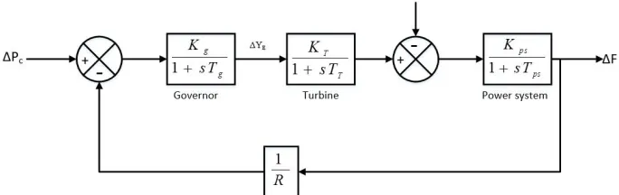
The mathematical model is necessary to analyse the system performance. Also, the control system design requires the complete mathematical model. In this paper the mathematical model of generator system and thermal system is considered. The thermal power plant is modelled for small signal analysis as shown in fig 1.
Fig.1 Common single line diagram of both areas
1. Generator System:-
The signal increment power input function of the generator system load is to be determined by the frequency deviation that can be specified as in the following equation (1). The modelling parameters of generator system transfer function is taken from [1]. Here, Δ is frequency deviation, Kps is power system gain, Δ is load perturbation, Δ is the incremental generator power and Tps is power system time constant.
∆ ( ) = [∆ ( )− ∆ ( )] (1)
2. Thermal Plant System:-
In a thermal plant system [6], ΔPC is the command signal coming from the pilot valve. The pilot valve controls the speed of the generator turbine by opening or closing which is governed by the error signal, generated by the deviation in frequency. This change in the steam valve setting is ΔYE. It can be given as
ΔY (s) = ΔP (s)− ΔF(s) (2)
Where, R is speed regulation of governor, Kg is speed governor gain constant, Tg is time constant of speed governor. The detailed control scheme is depicted in the fig. 2. Where, KT and TT are gain and time constant of turbine system respectively.
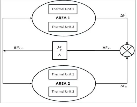
3. Connection of Two Area System:
The two area power system is connected by means of power lines known as the tie lines. It represents the ACE (area control error) of the system. In this type of multi-unit interconnected power system, the ACE [5] is subjected to the control action of tunable TID controller that forces this error signal of the steady state frequency deviation to zero. This is done by a tunable TID controller by generating continuous control action for reducing ACE as a linear tie line power and combination of frequency.
Fig. 3 Interconnection of areas via tie-line [4]
III.TILT-INTEGRAL-DERIVATIVE CONTROLLER (TID)
It consists of three components tunable feedback loop control system which includes a PID compensator. The only difference from the conventional controller is that the proportional compensating part of the system is replaced with a more suitable compensator which is having a transfer function Kt
1
1 s n . [3]
The term ‘Tilt’ implies that it can provide a feedback gain as a frequency function which is shaped or tilted with respect to gain frequency of conventional compensation unit.
The TID transfer function can be written as:
( ) =
11 s n + + (3) Where, n is a nonzero real number. It is preferable to use ‘n’ between 2 and 3.
The mathematical model of the above transfer function (3) is shown in fig 4
The effects of TID compensator can be summarized as:
feedback control is improved
simple tuning
disturbance rejection ratio is improved
plant parameter variation has less effect on closed loop response
The different values of transient parameters for different values of n are shown in the table 1.
Table I: Optimization results
n Overshoot (%) Undershoot (%) Settling time (s) Steady state error
2 1.125 3.425 11 0.025
2.1-2.9 1.117 3.421 13 0.025
3 1.100 3.415 16 0.025
3.1-3.9 0.940 3.410 19 0.025
4 0.750 3.400 22 0.025
Optimum tuning algorithm is used for tuning the TID controller for stabilising the frequency deviation response. The main parameter for tuning in TID controller is the tunable coefficient “n” and the other parameters (Ki and Kd) are the same as we used in conventional PID controller. The various characteristic parameters are shown in Table I according to various values of “n”. Thus, the most optimum value of “n” is obtained by this technique for the lower percent of under/overshoot, settling time and steady state error.
IV.SIMULATION RESULTS AND DISCUSSIONS
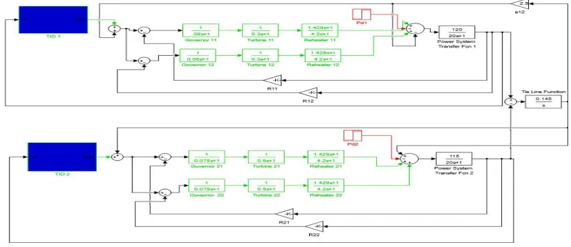
Two areas consisting two thermal units each have been combined using tie-line and mathematical model of whole system is simulated in the simulink environment of MATLAB as shown in the fig. 5. First the PID controller is used and the optimum values are obtained using simple optimization technique. Then the tunable TID controller is used with the variable values of ‘n’ as shown in the table 1.
Fig. 5 MATLAB/ Simulink model of two area power system
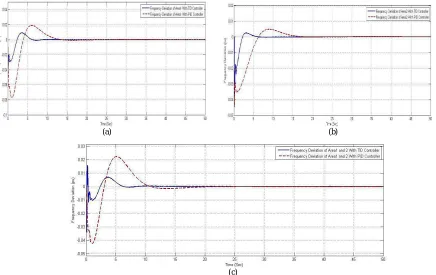
(a) (b)
(c)
Fig. 6 Frequency deviation response (a) Frequency response of area 1 (b) Frequency response of area 2 (c) Frequency response of both area 1 and area 2
The power system model consists of two area is being subjected to 10% load disturbance. After being disturbed the frequency of combined system is regulated and power balancing is carried out by the tie-line by which two areas are interconnected. The fig. 6(a) and fig.6(b) shows the frequency deviation response of area 1 and area 2 respectively and fig.6(c) shows the combined power system frequency response after 10% disturbance occurs. The frequency response results are compared with the classical PID, thus it is concluded that TID controller provides better frequency response.
Fig. 7 Tie line power response obtained from tunable TID control actions
V. CONCLUSION
As the power demand is increasing with the fast rapid rate, stability of power system becomes much challenging. Thus, Load frequency control (LFC) becomes more vital. In this paper LFC with 10% load penetration has been analysed on the multiunit (presence of two Thermal units in each area) two area power system with PID and tunable TID controllers. It is detected by the simulation results that by implemented TID control actions frequency deviation of each area as well as whole system is improved by means of its characteristic parameters such as peak overshoot and settling time within the tolerable limits. The Tie Line by which two areas are connected is also having the stable tie-line power response.
REFERENCES
[1] Atul Ikhe and Anant Kulkarni, “Load frequency control for two area power system using different controllers”, International Journal of Advances in Engineering & Technology, Sept. 2013.
[2] J .Syamala, I.E.S. Naidu, “Load Frequency Control of Multi-Area Power Systems Using PI, PID, and Fuzzy Logic Controlling Techniques”, International Conference on Engineering Technology and Science-(ICETS’14).
[3] Boris J. Lurie, La Crescenta, Calif, “Three parameter tunable tilt-integral-derivative (TID) controller”, United States Patent, Feb. 1, 1993. [4] Sachin Khajuria and Jaspreet Kaur, “Load Frequency Control of Interconnected Hydro-Thermal Power System Using Fuzzy and Conventional
PI Controller”, International Journal of Advanced Research in Computer Engineering & Technology (IJARCET), Vol. 1, Issue 8, October 2012.
[5] Dr.C.Srinivasa Rao, “Implementation of Load Frequency Control of Hydrothermal System under Restructured Scenario Employing Fuzzy Controlled Genetic Algorithm”,International Journal of Advanced Research in Electrical, Electronics and Instrumentation Engineering, Vol. 1, Issue 1, July 2012.
[6] N. Kiran Kumar and I.E.S. Naidu, “Load Frequency Control for A Multi Area Power System Involving Wind, Hydro and Thermal Plants”,