Cascaded H-Bridge Multilevel Inverter Based
D STATCOM for Power Quality
Improvement
S. Ramya1, P.Divya Banu 2, R.Rajendran3, G.Sundar3
Department of Electrical and Electronics Engineering, Sri Shakthi Institute of Engineering and Technology,
Coimbatore, Tamil Nadu, India
ABSTRACT: Cascaded multilevel configuration of the inverter has the advantage of its simplicity and modularity over the configurations of the diode-clamped and flying capacitor multilevel inverters. This paper presents a three-phase, five-level and seven level cascaded multilevel voltage source inverter based active filter for power line conditioning to improve power quality in the distribution network. The DSTATCOM helps to improve the power factor and eliminate the Total Harmonics Distortion (THD) drawn from a Non-Liner Diode Rectifier Load (NLDRL). The compensation process is based on concept of p-q theory. A CHB Inverter is considered for shunt compensation of a 11 kV distribution system. Finally a level shifted PWM (LSPWM) and phase shifted PWM (PSPWM) techniques are adopted to investigate the performance of CHB Inverter. The results are obtained through Matlab/Simulink software package.
KEYWORDS: DSTATCOM, Level shifted Pulse width modulation (LSPWM), Phase shifted Pulse width modulation (PSPWM), Cascaded H- Bridge Multilevel Inverter, Proportional-Integral (PI) control, CHB multilevel inverter, D-Q reference frame theory.
I. INTRODUCTION
The electric power system has grown in size and complexity with a huge number of interconnections to meet the increase in the electric power demand. Moreover, the role of long distance and large power transmission lines become more important. Now a days the requirement for power quality becomes more and more important to keep safety of the electrical devices and consumer satisfaction. Electric Power quality is a term which has captured increasing attention in power engineering in the recent years. Even though this subject has always been of interest to power engineers; it has assumed considerable interest in the 1990's. Electric power quality means different things for different people. To most electric power engineers, the term refers to a certain sufficiently high grade of electric service but beyond that there is no universal agreement [1]. The measure of power quality depends upon the needs of the equipment that is being supplied. What is good power quality for an electric motor may not be good enough for a personal computer. Usually the term power quality refers to maintaining a sinusoidal waveform of bus voltages at rated voltage and frequency. Electric power quality (EPQ) problems mainly include unbalance voltage and current, flicker, harmonics, voltage sag, dip, swell, and power interruption [2]. These power quality problems may cause abnormal operations of facilities or even trip protection devices. Hence, the maintenance and improvement of electric power quality has become an important scenario today.
real-power theory generates the reference currents required to compensate the distorted line current harmonics and reactive power. It also tries to maintain the dc-bus voltage across the capacitor constant. Another important characteristic of this real-power theory is the simplicity of the calculations, which involves only algebraic calculation A multilevel inverter can reduce the device voltage and the output harmonics by increasing the number of output voltage levels. There are several types of multilevel inverters: cascaded H-bridge (CHB), neutral point clamped, flying capacitor [4-5]. In particular, among these topologies, CHB inverters are being widely used because of their modularity and simplicity. Various modulation methods can be applied to CHB inverters. CHB inverters can also increase the number of output voltage levels easily by increasing the number of H-bridges.
II. DESIGNOFMULTILEVELBASEDDSTATCOM
A. Principle of DSTATCOM
A D-STATCOM (Distribution Static Compensator), which is schematically depicted in Fig-1, consists of a two-level Voltage Source Converter (VSC), a dc energy storage device, a coupling transformer connected in shunt to the distribution network through a coupling transformer. The VSC converts the dc voltage across the storage device into a set of three-phase ac output voltages. These voltages are in phase and coupled with the ac system through the reactance of the coupling transformer. Suitable adjustment of the phase and magnitude of the D-STATCOM output voltages allows effective control of active and reactive power exchanges between the DSTATCOM and the ac system. Such configuration allows the device to absorb or generate controllable active and reactive power.
Fig.1 Schematic Diagram of a DSTATCOM
The VSC connected in shunt with the ac system provides a multifunctional topology which can be used for up to three quite distinct purposes: 1. Voltage regulation and compensation of reactive power;
2.Correction of power factor 3.Elimination of current harmonics.
B. Control for Reactive Power Compensation
terminal voltage measured. Such error is processed by a PI controller; the output is the angle δ, which is provided to the PWM signal generator. It is important to note that in this case, of indirectly controlled converter, there is active and reactive power exchange with the network simultaneously.
Fig-2 PI control for reactive power compensation
The PI controller processes the error signal and generates the required angle to drive the error to zero, i.e. the load rms voltage is brought back to the reference voltage.
C. Control for Harmonics Compensation
The Modified Synchronous Frame method is presented in [6]-[7]. It is called the instantaneous current component (id-iq) method. This is similar to the Synchronous Reference Frame theory (SRF) method. The transformation angle is now obtained with the voltages of the ac network. The major difference is that, due to voltage harmonics and imbalance, the speed of the reference frame is no longer constant. It varies instantaneously depending of the waveform of the 3-phase voltage system. In this method the compensating currents are obtained from the instantaneous active and reactive current components of the nonlinear load. In the same
way, the mains voltages V(a,b,c) and the available currents il (a,b,c) in α-β components must be calculated as given by (1), where C
is Clarke Transformation Matrix. However, the load current components are derived from a SRF based on the Park transformation,
where “θ” represents the instantaneous voltage vector angle[8]-[9].
Fig-3 Block diagram of SRF method
Fig. 3 shows the block diagram SRF method. Under balanced and sinusoidal voltage conditions angle θ is a uniformly
increasing function of time. This transformation angle is sensitive to voltage harmonics and un balance; therefore d θ/d t may not be
constant over a mains period. With transformation given below the direct voltage component is
D. Cascaded H-Bridge Multilevel Inverter
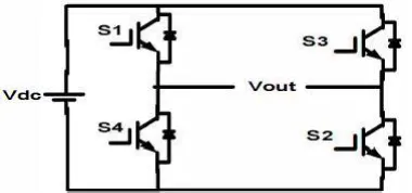
Fig4 shows the circuit model of a single CHB inverter Configuration. By using single H-Bridge we can get 3 voltage levels. The number of output voltage levels of CHB is given by 2n+l and voltage step of each level is given by Vdc/2n, where n is number of H-bridges connected in cascaded [10]. The switching table is given in Table l.
Table-l Switching table of single CHB inverter
Fig. 5 Block diagram of 5-level CHB inverter model
The switching mechanism for 5-level CHB inverter is shown in table-2.
III.RESULTS
Case 1: Implementation of D-Statcom using Phase Shifted Modulation Technique
Fig.6 Proposed Model
Fig.6 shows the Matlab/Simulink Model of proposed Compensator using Phase Shifted Modulation Technique based CHB D- STATCOM.
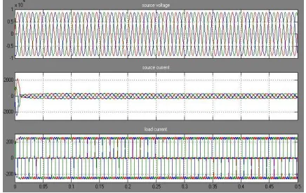
Fig. 7 Source Voltage, Source Current, Load Current with Compensator
Fig.7 shows the Source Voltage, Source Current, Load Current with Compensator, due to non-linear diode rectifier pollutes source side current, with compensator we get source current is sinusoidal.
Fig.8 shows the Source side Power Factor, both voltage & current are maintained sinusoidal and in phase condition.
Fig.9 FFT Analysis of source current with compensator using PS Modulation Technique
Fig.9 shows the FFT Analysis of source current with compensator using PS Modulation Technique, we get THD is 4.83%.
Case 2: Implementation of D-Statcom using Level Shifted Modulation Technique
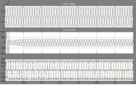
Fig. 10 Source Voltage, Source Current, Load Current with Compensator
Fig.10 and 11 shows the Source side Power Factor, both voltage & current are maintained sinusoidal and in phase condition.
Fig.12 FFT Analysis of source current with compensator using LS Modulation Technique
Fig.12 shows the FFT Analysis of source current with compensator using LS Modulation Technique, we get THD is 1.95%.
IV. CONCLUSION
A five level cascaded multilevel voltage source inverter based DSTATCOM using instantaneous real-power controller is found to be an effective solution for power line conditioning. DSTATCOM with the proposed controller reduces harmonics and provides reactive power compensation due to non-linear load currents; as a result source current(s) become sinusoidal and unity power factor is also achieved under both transient and steady state conditions. The proposed instantaneous real-power controller uses reduced computation for reference current calculations compared to conventional approach. The cascaded inverter switching signals are generated using triangular-sampling current controller; it provides a dynamic performance under transient and steady state conditions. As evident from the simulation studies, dc bus capacitor voltage settles early and has minimal ripple because of the presence of PI-controller. The THD of the source current is investigated for both PSCPWM and LSCPWM for a five level inverter based DSTATCOM. THD simulation results under non-linear loads are investigated and found that the LSCPWM results are better than PSCPWM.
REFERENCES
[I] K.A Corzine. and Y.L Familiant, "A New Cascaded Multi-level Hbridge Drive:' IEEE Trans. Power.Electron .• vol. I 7. no. I. pp. I 25-I 3 I . Jan 2002.
[3] T.A.Maynard. M.Fadel and N.Aouda. "Modelling of multilevel converter:' IEEE Trans. Ind.Electron .• vo1.44. pp.3S6-364.
Jun. I 997.
4] P.Bhagwat. and V.R.Stefanovic. "Generalized structure of a multilevel PWM Inverter:' IEEE Trans. Ind. Appln, VoI.IA- 19. no.6, pp. I OS7-1069, Nov.!Dec .. 1983. G.Sundar, S. Rama Reddy, “Digital simulation of Multilevel inverter Based STATCOM” published in International Journal of Theoretical and Applied Information Technology, Vol.12, No.12, Feb.2010, pp.19-24
[5]. Satyanarayana, G.; Prasad, K.N.V.; Kumar, G.Ranjith; Ganesh, K.Lakshmi, "Improvement of power quality by using hybrid fuzzy controlled based IPQC at various load conditions," Energy Efficient Technologies for Sustainability (ICEETS), 2013 International Conference on , vol., no., pp.1243,1250, 10-12 April 2013.
[6] Roozbeh Naderi, and Abdolreza rahmati, "Phase-shifted carrier PWM technique for general cascaded inverters," IEEE Trans. Power.Electron., vo1.23, no.3, pp. I 257-I 269. May.2008.
[7] Prasad, K.N.V.; Kumar, G.R.; Kiran, T.V.; Narayana, G.S., "Comparison of different topologies of cascaded H-Bridge multilevel inverter," Computer Communication and Informatics (ICCCI), 2013 International Conference on , vol., no., pp.1,6, 4-6 Jan. 2013.
[8] Bhim Singh, Kamal AlHaddad & Ambrish Chandra, 1999, A Review of Active Filter for Power Quality Improvements, IEEE Trans on Industrial Electronics, 46(S), pp.960970 G.Sundar, N.Karthick, S. Rama Reddy, “ High step up DC-DC converter for AC photovoltaic module with MPPT control” published in Journal of Electrical Engineering, Vol.65, No.4, Aug.2014, pp.248-253.
[9] Mauricio Angulo, Pablo Lezana, Samir Kouro, Jos'e Rodr'lguez and Bin Wu, "Level-shifted PWM for Cascaded Multilevel Inverters with Even Power Distribution" IEEE Power Electronics specialist conference, 17-21 june 2007, pp.2373-2378.