20th International Conference on Structural Mechanics in Reactor Technology (SMiRT 20) Espoo, Finland, August 9-14, 2009 SMiRT 20-Division V, Paper 1811
Off-Axis Underground Soil Pressures from Surface Impact Loads
William H. Johnson, Necip Onder Akinci, Mukti L. Das
Bechtel Power Corporation, Frederick, Maryland USA, [email protected]
Keywords: dynamics, impact, underground, utilities, waves
1
ABSTRACT
The heavy rigging operations necessary at nuclear plant sites during construction, routine maintenance, and special activities such as steam generator replacement require assessment of safety related buried utilities for the effects of postulated accidental impact loads in the form of dropped loads, crane boom drops, etc. The conventional system response methodology is to estimate the free-field wave motion resulting from the surface impact loading, to apply these free-field soil motions to the buried pipeline or duct bank and to determine the structural response. Published solutions for the free-field response emphasize the special and more mathematically tractable cases of either the soil surface response at distance from the impact or the on-axis soil response at depth directly below the location of impact. This investigation considers the analysis for the general off-axis, below surface response. Parametric results are provided for estimation of the off-axis free-field response at arbitrary locations below the ground surface based on non-dimensionalized elastic half-space dynamic transient finite element solutions. These results, developed using ANSYS finite element software, are benchmarked with known analytical results for the limiting cases at the surface and on-axis. Rectangular temporal pulses of constant amplitude over a small circular impact area are considered. The nondimensionalized responses are presented as a set of design charts which relate missile energies and geometries to soil stresses. Guidelines, based on empirical penetration formulae are provided for development of the applied surface impact loads.
2
INTRODUCTION
The conventional system response methodology for underground structures subject to surface impact loads is to estimate the free-field stress wave amplitude resulting from the surface impact loading (in the form of peak particle velocities), to apply these free field responses to the buried pipeline or ductbank and to determine the structural response using methods such as those available in Yeh (1974) and Hashash et al. (2001). The free-field velocity due to impact loading is, however, difficult to determine analytically, primarily due to the unavailability of utilitarian solutions to the elastic half-space surface impact load problem. As such, nuclear plant structural engineers have employed data collected for various impact phenomena, such as pile driving, construction equipment vibrations, blasting, soil compaction, etc. This data has been typically presented in the form of surface peak velocities as a function of the distance from the impact or as peak particle velocity vs. scaled energy [Wiss (1981), Lukas (1980), Woods and Jedele (1985)]. Data for measurements beneath the surface are rare, first because the purpose of this data is generally for use in evaluating the potential for damage to surface mounted structures such as buildings, and secondly because of the difficulty and expense of acquiring reliable undisturbed in-situ data below the surface. For evaluation of nuclear plant buried safety related components, conservative data for the surface soil response has been used at locations below the surface.
system or an outside lift system header beam from a crawler crane, onto or near safety-related utilities serving a sister on-line unit, these considerations can be substantial enough to dictate the layout and design of the rigging equipment. Increased flexibility to perform construction operations and improved scheduling is afforded if conservative assumptions for the impact loadings from postulated component and construction element drops are relaxed.
A number of approaches can be applied to calculate the subsurface response of an elastic half space to surface impact loads; solution of the partial differential equation by integral transform methods, finite difference formulations, and finite element analysis. The first of these is problematic in that it involves the numerical inversion of the Laplace-Hankel transform, a formidable task, requiring either numerical complex integration with extremely refined localized meshes at singularities or the numerical evaluation of numerous real integrals. Such solutions have been published in the literature [Georgiadis et al. (1999), Laturelle (1990)], but only for special and limiting loadings (step functions) and for specific response locations (surface or on-axis). In some cases, the simplifying assumptions required to achieve a solution, render the results (such as infinite velocities for finite loadings) unsuitable for design application.
For this investigation, non-dimensionalized axisymmetric finite element response solutions are developed at locations throughout the half-space and presented in parametric form for the range of impulse and soil characteristics applicable to most nuclear plant postulated load drops.
Figure 1. Raleigh Wave Amplitude Variation with Depth [Richart et al. (1970)]
3
METHODOLOGY
This section describes the development of the impact loading for implementation with the finite element solution and the nondimensionalization transformations.
3.1
Determination of the impact loading
Two methods are used to define the impulse resulting from a direct missile impact onto a ground surface. The first method is based on empirical equations for the penetration depth, developed by Young (1969). This penetration, X, is given by
X= 0.0031SN(W/A)1/2(V-100) V ! 200 (2)
where
X = penetration distance (ft)
S = soil constant given by Young (1969)
N = missile nose performance coefficient given by Young (1969) W = weight of missile in pounds
A = cross-sectional area of missile V = striking velocity of missile (ft/sec)
The approach to determination of the applied impulse taken here follows the established methodologies [ASCE (1980) and Johnson (1986)] for interface forces resulting from missile impact with a barrier. This approach consists of estimating the “missile” penetration using an appropriate empirical formula, and assuming a uniform deceleration, and corresponding constant resisting force, F. By conservation of the missile kinetic energy,
F = WV2/2gX (3)
where g is the gravitational acceleration constant. From the uniform acceleration assumption, the rectangular impulse duration for the temporally uniform force, F, follows as
td = 2X/V (4)
Alternatively, the ultimate dynamic bearing pressure of the soil can be determined (this is the force, F, for a rectangular impulse), and the soil resisting force calculated by integrating this force over the missile cross-sectional area. The energy defined by the pressure from the resisting force, integrated over the surface depression is then equated to the missile kinetic energy at impact to determine the penetration depth. Once the penetration depth is known, td is determined as above. This alternate approach is more appropriate for
broad-nosed, large cross-sectioned missiles, as the empirical results are less accurate for shallow penetrations.
3.2
Nondimensionalization
The governing system of partial differential equations for the axisymmetric case of a dynamically loaded elastic half-space (Figure 2) are given by Manning and Hargrove (1998) as
2 2 2 2
r r r z r r
2 2 2 2
u 1 u u u u u
( 2 ) ( )
r r r r r z z t
!+ µ #'$ + $ & %(+ !+µ #'$ (%+µ$ ="$
$ $ ) $ $ $ $
* * )
(5)
2 2 2 2
z r r z z z
2 2 2
u u 1 u 1 u u u
( 2 ) ( )
z r z r z r r r t
!+ µ #&$ %'+ +! µ #&$ + $ '%+µ#& $ +$ %'="$
$ ) $ $ $ ) ( $ $ ) $
( (
(6)
where t is time, uz and ur are the vertical and radial displacements, ρ is the soil mass density and λ and µ are
!
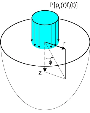
P[pr(r)ft(t)]
r
z o
Figure 2. Axisymmetric Impact Load Applied to Elastic Half-Space
Compacted structural backfill is the surface soil material installed in the “Protected Area” at most nuclear plants. For this material, ν is in the range 0.30 to 0.36 [Leonards (1962)]. An average value of
ν = 1/3 is used in the present study. The definitions for non-dimensionalized variables follow Laturelle
(1990) with non-dimensional variables defined as R = r/r0, Z = z/r0, τ = cst/r0, u = µur/Pr0 and w = µuz/Pr0,
where cs is the soil shear wave velocity, r0 is the radius over which the time dependent surface load is
distributed, and P is the peak pressure amplitude determined from an impulse loading function assumed to be of the form P[pr(r)ft(t)] where pr(r) is a unit loading over the disc of radius, r, and ft(t) is a rectangular time
pulse of unit amplitude. Dimensional principal stresses in the soil are related to nondimensional principal stresses by the factor PE/µ = 2P(1+ν), where E is the soil elastic modulus and µ is the soil shear modulus.
4
MATHEMATICAL MODEL
Finite element analysis for the subsurface responses of a homogeneous elastic half-space under transient axisymmetric surface loading has long been a practical and achievable, though not routine, engineering computation. As such, the emphasis of this investigation is not on the consideration of the methodologies to solve such a problem, but on the presentation of response results, applicable to the problem at hand, so that such case-by-case solutions are unnecessary. The objective is to produce a general subsurface response tool which provides subsurface free-field principal stresses at an arbitrary depth below and distance from a surface impact load. So that the tool is as general as possible, the following assumptions and conditions are invoked for the input parameters:
1. Soil material damping, which for seismic soil response is around 5 % [USNRC (1980)], is neglected. This enables treatment of all soils, but is not unduly conservative, since its effect is generally small compared to that of geometric damping. Further, the initial response impulse peak occurs only a short time following arrival of the dominant wave, so that damping has little effect on the maximum response.
2. The impulse is assumed to have a disc shaped footprint and to be uniform in time. Other time and spatial variations can be conservatively enveloped by appropriately equivalencing them to a rectangular pulse. Equivalent disc shaped footprints can be determined based on area, provided that the radius of the equivalent disc is less than 3 times the distance to the response location of interest. Awrejcewicz and Pyryev (2003) demonstrated that the St. Venant considerations apply to the surface Raleigh wave when this condition is satisfied. The actual temporal variation of the impact pressure may also be equivalenced to a rectangular shape by integration. When this is done, it is recommended that equivalencing be done using both the td of the pulse for the equivalenced
rectangle and in turn, using the peak force, and calculating a td. The response from these two results
should then be enveloped.
Areas” range upwards from 1000 ft/sec. For greater impulse durations, and practical soil stiffnesses, there is essentially no increase in maximum response beyond the maximum response for the 0.01 second duration pulse. The nondimensional response plots provided envelope parameters in these ranges.
The modeling philosophy was to provide a model with boundaries sufficiently distant from the target so that maximum responses at the desired distance from the target will occur prior to the arrival of wavefronts at the boundaries. In this manner, wave reflection is eliminated and the model responses approximate those of a truly infinite elastic half-space. The finite element analysis is performed using the ANSYS computer program (2007) and the model shown in Figure 3, comprised of ANSYS (2007) Plane 42 elements with axisymmetric behaviour and 2 degrees-of-freedom of at each node. Two types of models were used; square element, uniform mesh models with horizontal and vertical model dimensions and numbers of elements adjusted as convenient and necessary to satisfy wave reflection requirements, and a model comprised of a refined mesh in the vicinity of the loading to better facilitate comparisons with analytical response solutions close to the point of load application. The z-axis nodes are fixed against horizontal displacements and the nodes along the bottom edge of the model were fixed against vertical displacement. Surface pressure loadings are applied over a circle of radius equal to one element dimension for the model with uniform mesh and twelve element dimensions for the refined model. Load footprint size assumption does not affect the response at distance from the impact, as discussed above.
Prior to obtaining transient response solutions, the static model was benchmarked against the closed form Bousinessq solutions and stresses and displacements were found to be in agreement to within three-tenths of one percent. At locations sufficiently distant from the point of load application, the FEA transient results showed good agreement with the integral transform solutions of Guan and Novak (1994) for the surface response and with the integral transform solutions of Laturelle (1990) on the axis as shown in Figure 4.
P(r,t)
r
z
!
Figure 3. Axisymmetric Finite Element Model
superposed wave types, the relative contributions of which are unknown. In addition to the general unavailability of appropriate solutions for direct comparison and benchmarking of the present result, other factors limit such comparisons. These factors include the necessity to incorporate horizontal restraints on the z-axis boundary when using the axisymmetric modeling technique. The on-axis location, which is where the benchmarking is performed, will have the least reliable responses, due to the spurious effects produced, locally, by this boundary condition. Another factor, is the desirability, for this investigation, to realistically consider the missile as a rigid impacting element, imposing the applied load by displacing a rigid massless disc at the surface (rather than applying a true, uniformly distributed load) as was done in the cited references. These two methods for application of the impulse load show marked time history response differences within 3 or 4 diameters of the loading footprint. The comparison in Figure 4(a) shows good agreement between the analytical and finite element soil responses at the surface. From Figure 4(b), and other similar comparison plots not shown, it can be concluded that the on-axis stress responses correlate reasonably well at distance from the applied loading. However, due the availability of alternative approximate formula for the on-axis subsurface response to impact [Mayne and Jones (1983)], and the uncertainty of the depth at which the finite element solution has acceptable accuracy, it is recommended that the finite element results of Figure 6 for φ = 0 not be used in design.
(a) Surface Vertical Displacement Time Histories (b) On-Axis Vertical Stress (1 kip peak load, r0 = 1 ft., cs = 1000 ft/sec)
-0.00015 -0.0001 -0.00005 0 0.00005
0 0.005 0.01 0.015 0.02
Time (sec) V e r ti c a l D is p la c e m e n t ( in ) . Finite Element Guan and Novak (1994)
-2.0 -1.5 -1.0 -0.5 0.0 0.5
0.0 1.0 2.0 3.0
Nondimensional Distance Z
N o n d im e n s io n a l V e rt ic a l S tr e s s Finite Element Laturelle (1991)
Figure 4. Comparison of Finite Element and Analytical Results
5
ANALYSIS RESULTS
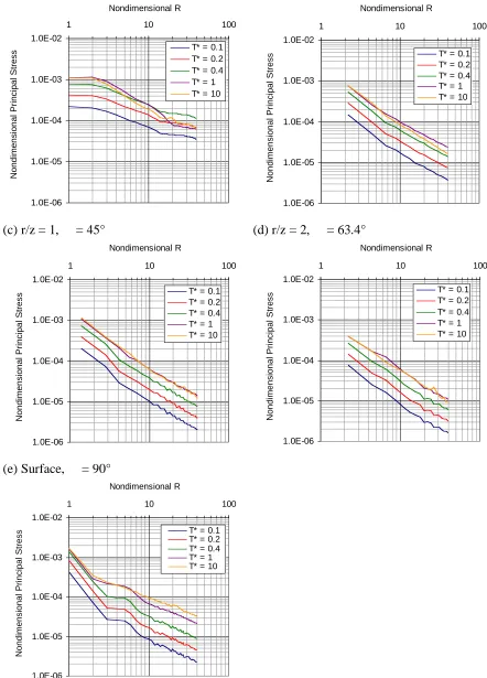
Since free-field subsurface pressures are the most useful soil responses for the analysis of the buried utility structural response, these are the characterizations provided here (Figure 5).
6
APPLICATION TO BURIED COMMODITIES
For buried open-section commodities subject to high-energy surface impact loads, the major structural responses are the cross-sectional distortion modes (ovaling, buckling, and through-wall compression) and the longitudinal shear-flexural response. Calculation of response for the cross-sectional distortion modes has been reported on extensively in the literature for open sections of various materials in Hashash (2001), American Lifeline Alliance (2001), Bulson (1984) and elsewhere. Typically, these methods evaluate the cross-section response based on a pipe-soil interacting model under a free-field pseudo-static pressure loading corresponding to either a compression wave or shear wave propagating in a direction transverse to the commodity longitudinal axis.
For application of the free-field soil motions to the determination of the commodity longitudinal structural response, the free-field soil strains are imposed directly on the buried structure. Formulas have been developed for the structure axial strains and curvatures in terms of the soil peak particle velocities, peak ground displacements and peak ground accelerations for shear, compression or Rayleigh waves propagating at arbitrary angles of incidence with respect to the commodity longitudinal axis [see, for example, Table 5 of Hashash et al. (2001)].
For convenience, conservatism, and compactness of presentation, maximum principal stresses rather than individual stress components have been reported in this investigation. These results are not intended for use on the loading axis or on the surface, where one wave type or another dominates the response. As such, there is no direct correspondence between the reported principal stress amplitude and a particular wave type. Since the soil stress components producing the maximum principal stress are not known, the strains associated with the principal stress cannot be computed directly. For either the cross-sectional or longitudinal response, an approximate and conservative approach for calculation of the soil strains is to assume that they are in turn produced by compression, shear or Rayleigh waves, respectively, and to impose these strains onto the buried commodity, using the relations in Table 5 of Hashash et al. (2001) or equivalent. This “back-calculation” approach for soil strain is not unduly conservative when one considers the alternative of using either the on-axis or surface response (based on location of the commodity at the corresponding projected on-axis or surface coordinate). As discussed in Section 2, subsurface responses can be an order of magnitude less than the corresponding on-axis or surface responses, whereas a mismatch of normal stress or shear stress with shear modulus or compression modulus, respectively, can result in an error factor of at most E/G or 2(1+ν). Some judgement is required in the implementation of this approach; for example, response at locations off-axis, but “near” the surface will be dominated by Rayleigh waves, and should use the appropriate Rayleigh wave formula to calculate the soil strains.
1.0E-06 1.0E-05 1.0E-04 1.0E-03 1.0E-02
1 10 100
Nondimensional R N o n d im e n s io n a l P ri n c ip a l S tr e s
s T* = 0.1
T* = 0.2 T* = 0.4 T* = 1 T* = 10
1.0E-06 1.0E-05 1.0E-04 1.0E-03 1.0E-02
1 10 100
Nondimensional R N o n d im e n s io n a l P ri n c ip a l S tr e s
s T* = 0.1
T* = 0.2 T* = 0.4 T* = 1 T* = 10
(c) r/z = 1, = 45°
1.0E-06 1.0E-05 1.0E-04 1.0E-03 1.0E-02
1 10 100
Nondimensional R N o n d im e n s io n a l P ri n c ip a l S tr e s
s T* = 0.1
T* = 0.2 T* = 0.4 T* = 1 T* = 10
(d) r/z = 2, = 63.4°
1.0E-06 1.0E-05 1.0E-04 1.0E-03 1.0E-02
1 10 100
Nondimensional R N o n d im e n s io n a l P ri n c ip a l S tr e s
s T* = 0.1
T* = 0.2 T* = 0.4 T* = 1 T* = 10
(e) Surface, = 90°
1.0E-06 1.0E-05 1.0E-04 1.0E-03 1.0E-02
1 10 100
Nondimensional R N o n d im e n s io n a l P ri n c ip a l S tr e s
s T* = 0.1
T* = 0.2 T* = 0.4 T* = 1 T* = 10
Figure 5. Peak Nondimensional Stress vs. Nondimensional R = r/r
0
(for nondimensional pulse duration, T* = c
st
d/r
0)
(c) t = 0.0375 sec
(d) t = 0.0500 sec
Figure 6. Snapshots of Wave Propagation from Surface Impact Load
7
REFERENCES
American Lifeline Alliance, Guidelines for the Design of Buried Steel Pipe, 2001.
ANSYS Version 11, User Manual, ANSYS, Inc. Software Products, Pennsylvania, 2007.
ASCE Special Publication No. 58, Structural Analysis and Design of Nuclear Plant Facilities, 1980, ASCE
Awrejcewicz, J., Pyryev, Y., “The Saint –Venant Principle and an Impact Load Acting on an Elastic Half-Space”, Journal of Sound and Vibration, 264 (2003), pp. 245 – 251
Bulson, P. S., Buried Structures: Static and Dynamic Strength, Chapman and Hall, 1984.
Eason, G., The displacements produced in an elastic half-space by a suddenly applied surface force, J. Inst. Math. Appl., Vol 2, pp. 299-326, 1966.
Georgiadis, H.G., Vamvatsikos, D., Vardoulakis, I., Numerical Implementation of the Integral-Transform Solution to Lamb’s Point-Load Problem, Computational Mechanics, Vol. 24, 1999, pp. 90-99.
Guan, F., and Novak, M., “Transient Response of an Elastic Homogeneous Half-Space to Suddenly Applied Rectangular Loading,” Journal of Applied Mechanics, Vol. 61, June 1994, pp. 256-263.
Johnson, L. R., Green’s function for Lamb’s problem, Geophys.J. Royal Astron. Soc., Vol. 37, pp. 99-131, 1974.
Johnson, W., “Historical and Present-Day References Concerning Impact on Wood”, Int. J. Impact Engrg., Vol. 4, pp. 161-174, 1986.
Laturelle, F. G., The Stresses Produced in an Elastic Half-Space by a Normal Step Loading Over a Circular Area Analytical and Numerical Results, Wave Motion, Vol. 12, 1990, pp. 107-127.
Laturelle, F. G.,The Stresses Produced in an Elastic Half-Space by a Pressure Pulse Applied Uniformly over a Circular Area: Role of the Pulse Duration, Wave Motion, Vol. 14, 1991, pp. 1-9.
Leonards, G. A., Foundation Engineering, McGraw-Hill, 1962.
Lukas, R. G., Densification of Loose Deposits by Pounding, Journal of the Geotechnical Engineering Division, ASCE, Volume 1206, No. GT4, April 1980, pp 435-446.
Manning, P., Hargrove, G., “Elastic wave finite difference modeling as a practical exploration tool”, CREWES Research Report, Vol. 10, 1998.
Mayne, P.W., Jones, J.S., “Impact Stresses During Dynamic Compaction”, Journal of Geotechnical Engineering, ASCE, 1983, Vol. 109, No. 10, pp. 1342-1346.
Richart. F. E., Hall, J. R., Woods, R. D., Vibrations of Soils and Foundations, Prentice-Hall, 1970.
USNRC (United States Nuclear Regulatory Commission), Generic Letter No. GL80109, Dec. 15, 1980, Guidelines for SEP Soil-Structure Interaction Reviews.
Wiss, J. F., “Construction Vibrations: State-of-the-Art”, ASCE Journal of Geotechnical Engineering Division, Vol. 107, No. GT2, Feb., 1981, pp. 167-181.
Woods, J. R., Jedele, L.P. “Vibration Problems in Geotechnical Engineering”, Eds. Gazetas and Selig, ASCE Special Technical Publication, 1985.
Yeh, C. K., Seismic Analysis of Slender Buried Beams, Bulletin of the Seismological Society of America, Vol. 64, No. 5, pp. 1551-1562, October, 1974.