Single Axis Solar Tracker for Parabolic
Trough Cylindrical Concentrator
A.NagamaniPrabu1,B. Janarthanan2,G.Manikandan3
Research Scholar, Department of Physics, Karpagam University, Coimbatore, Tamil Nadu, India.1
Associate Professor, Department of Physics, Karpagam University, Coimbatore, Tamil Nadu, India.2
P.G. Student, Department of Physics, Sri Ramakrishna mission Vidyalaya College of arts and Science, Coimbatore,
Tamil Nadu, India.3
ABSTRACT: An attempt is made to design and construct a single axis tracking system for the line focused
concentrator. Equal arm balance structure is proposed and analyzed for the number of clear sunny days to track the parabolic trough system towards the motion of the sun. The system is made with the local available materials and can be used for small portable system with the less maintenance. The system is cost, effective and economical so that the technology can be extended to the parabolic trough system of large aperture area.
KEYWORDS: single axis solar tracker, parabolic trough system, equal arm balance
.
I.INTRODUCTION
Solar tracker is an indispensable increases the thermodynamic efficacy of the parabolic trough system by orienting the collector towards the motion of the sun. The tracker is made to operate manually as well as automatically using discrete elements such as LDR, photodiodes. In such tracker, the sensors used are highly sensitive for weather condition such as temperature and humidity. Researchers have made sincere efforts to design and fabricate an efficient tracking system and succeeded.
FabienneSallaberryet al. (2015) have proposed a procedure to characterize the accuracy of the single axis solar tracker. Positioning angle error of a parabolic trough collector is estimated directly and the angular tracking error of 0.4 with average optical loss of 0.317%is found. A single axis three position (1A-3P) low-cost sun tracker is tested by the Bin-Juine Huang et al. (2013) for south, southeast and south west orientation. It is observed that the energy loss of 1A-3P PV system due to misalignment of South is negligible and energy loss of 4.42-6.82% and 4.31-6.79% for southeast and southwest orientations.
microcontroller computing real-time altitude and azimuth of the sun. Codruta Jaliuet al. (2013 ) have designed a new actuator variant for the tracking system with the DC/AC motor ensuring high transmission ratio and the study revealed that the design complication and losses due to the friction and it has been reduced. Dehelean and Dehelean (2011) have proposed a mechanism for the implementation of the reflection function to orient the heliostat set of mirrors that track the sun. The results of the study indicated the effectiveness of the heliostat field for the production of electricity. Ahmad Parvareshet al. ( 2011) have attempted to design a tracking system based on azimuth and elevation angle of the sun. The performance of the tracking system has been compared with the tracking system based on the optical sensor. It is found that the efficiency is higher than the system with the optical sensors.
In the present study, an attempt has been made to design a new tracking system with the equal arm balance method depending on the mass of the parabolic trough system. Theoretical calculations have been done and compared with the experimental results of the system during the tracking towards the motion of the sun.
II. MATERIALS AND METHODS
II. 1Parabolic trough
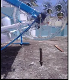
Parabolic trough system of 2m length is fabricated with the mild steel and the reflector is pasted on the curved surface of the trough. The trough is mounted on a supporting stand provided with the axle, bearing and spacer to undergo the spontaneous rotation at any instant of time. The focal line of the trough system is at 0.135m from the centre of the curved base and receiver made of copper tube is mounted on the focal line. The aperture area of the parabolic trough is 1m2. Pressure head has been used to flow the heat transfer fluid through the copper tube to provide the required pressure. The tracking mechanism for the trough has been designed using equal arm balance method and separate water tank is used to circulate water for tracking. Fig. 1 represents the schematic diagram of the trough system and photograph of the proposed system is depicted in the Fig. 2. Necessary hardware accessories used for the fabrication of parabolic trough system has been depicted in the Fig. 3.
Fig. 2 Photograph and Schematic diagram of the proposed parabolic trough system
Fig. 3 Hardware accessories for the fabrication of parabolic trough system
II.2 Construction of equal arm balance structure
Fig. 4 Photograph of the trough system with the initial adjustment
Fig. 5 Photograph of 2m Parabolic Trough with the Fig. 6 Photograph of 1m Parabolic Trough the Tracking SystemTracking System
Table. 1 Design specifications of 1m and 2m parabolic trough system
Description Material Specification m Weight kg
1 m 2m 1m 2 m
Reflector (ss) SS Sheet (2mm) 1*1 2*1 1.568 3.136
Rectangular frame(Ms)
MS Square Pipe 1*0.64 2*0.64 5.115 6.015
Curvature MS Flat Plate (thick 7mm)
2 3 1.008 1.512
Bolt nut connector Iron steel 0.112 0.612
Axle (17 mm) Ms polish rod 0.2 0.2 0.7055 0.7055
Parabolic Trough 1 2 8.5085 11.6205
III. RESULTS AND DISCUSSION III.1 Experimental Work
Experiments have been done from 9am to 4 pm with the parabolic trough system with the proposed tracking mechanism in the Department of Physics, Karpagam University, Coimbatore, Tamilnadu, India. Initially, the 1m parabolic trough is oriented towards east at 9 am with the mass of water about 2.1834 kg in the eastern side tank TS1. It is observed that, for the rotation of 1/4 minutes tilt has been obtained with the addition of 0.04852 kg in the western side tank (TS2). Similarly, water mass of about 0.065475 kg is required for 2m parabolic trough system.
Water flow rate in the western side tank has been controlled by using the speed governor to control the rotatory motion of the trough system. To verify theoretically, a simple mathematical formula has been derived.
IV MATHEMATICAL EXPRESSION
III.2 Mass conversion equation
Total mass of the entire body is distributed through the radius of the collector its shape is semi-circle. Total angle to be tilted for east to west is π
Mass required for tilting an angle of 1◦ = (1)
In case additional mass is prerequisite to be calculated by
Mass required for tilting an angle of 1◦ = + (2)
To find weight to keep the trough in a balanced position, Total weight of the trough MT =11.6205 kg
To maintain the trough in a balanced position, required weight of water in both eastern and western water container is found to be L=R (Mc) = 5.9175 kg
Mass of water required in western side container per unit degree twist is 0.06575 kg/s (Ma) as the angle to be swept at 12 noon is 90 and is the required degree to be tilted. Thus the total mass of water is found to be
MT =(MC +Maα)+(MC -Maα) (3)
Further, the mechanism can be used to the system with different weight and additional weight is incorporated as Madded and can be written in the equation for tilt as
= − (4)
For the above expression, the plane of the trough is perpendicular to the sun’s ray and satisfies the balanced condition as
tan 180°(
) − =tan 180°( )+tanα
(5) tan( + ) + tan( − ) = 0
Based on the Eqs. 4 and 5, Figs. 7 and 8 represents the angle for tilt for twist angle and it is clear from the figures that, at any desired position, sun’s rays is always perpendicular to the plane of the trough system.
Fig. 7 Desired position of the trough towards west perpendicular to sun’s rays
Fig. 8 Desired position of the trough towards east perpendicular to sun’s rays
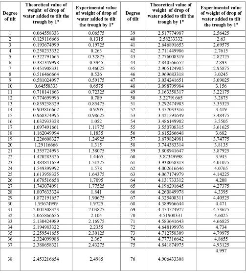
Table. 2 Experimental and theoretical values of mass of water added per second in western side container,
Degree of tilt
Theoretical value of weight of drop of water added to tilt the
trough by 1
Experimental value of weight of drop of water added to tilt
the trough by 1
Degree of tilt
Theoretical value of weight of drop of water added to tilt the
trough by 1
Experimental value of weight of drop of water added to tilt
the trough by 1
1 0.064558333 0.06575 39 2.517774987 2.56425
2 0.129116666 0.1315 40 2.58233332 2.63
3 0.193674999 0.19725 41 2.646891653 2.69575
4 0.258233332 0.263 42 2.711449986 2.7615
5 0.322791665 0.32875 43 2.776008319 2.82725
6 0.387349998 0.3945 44 2.840566652 2.893
7 0.451908331 0.46025 45 2.905124985 2.95875
8 0.516466664 0.526 46 2.969683318 3.0245
9 0.581024997 0.59175 47 3.034241651 3.09025
10 0.64558333 0.6575 48 3.098799984 3.156
11 0.710141663 0.72325 49 3.163358317 3.22175
12 0.774699996 0.789 50 3.22791665 3.2875
13 0.839258329 0.85475 51 3.292474983 3.35325
14 0.903816662 0.9205 52 3.357033316 3.419
15 0.968374995 0.98625 53 3.421591649 3.48475
16 1.032933328 1.052 54 3.486149982 3.5505
17 1.097491661 1.11775 55 3.550708315 3.61625
18 1.162049994 1.1835 56 3.615266648 3.682
19 1.226608327 1.24925 57 3.679824981 3.74775
20 1.29116666 1.315 58 3.744383314 3.8135
21 1.355724993 1.38075 59 3.808941647 3.87925
22 1.420283326 1.4465 60 3.87349998 3.945
23 1.484841659 1.51225 61 3.938058313 4.01075
24 1.549399992 1.578 62 4.002616646 4.0765
25 1.613958325 1.64375 63 4.067174979 4.14225
26 1.678516658 1.7095 64 4.131733312 4.208
27 1.743074991 1.77525 65 4.196291645 4.27375
28 1.807633324 1.841 66 4.260849978 4.3395
29 1.872191657 1.90675 67 4.325408311 4.40525
30 1.93674999 1.9725 68 4.389966644 4.471
31 2.001308323 2.03825 69 4.454524977 4.53675
32 2.065866656 2.104 70 4.51908331 4.6025
33 2.130424989 2.16975 71 4.583641643 4.66825
34 2.194983322 2.2355 72 4.648199976 4.734
35 2.259541655 2.30125 73 4.712758309 4.79975
36 2.324099988 2.367 74 4.777316642 4.8655
37 2.388658321 2.43275 75 4.841874975 4.93125
38 2.453216654 2.4985 76 4.906433308
Degree of tilt
Theoretical value of weight of drop of water added to tilt the
trough by 1
Experimental value of weight of drop of water added to tilt
the trough by 1
Degree of tilt
Theoretical value of weight of drop of water added to tilt the
trough by 1
Experimental value of weight of drop of water added to tilt
the trough by 1
77 4.970991641 5.06275 121 7.811558293 7.95575
78 5.035549974 5.1285 122 7.876116626 8.0215
79 5.100108307 5.19425 123 7.940674959 8.08725
80 5.16466664 5.26 124 8.005233292 8.153
81 5.229224973 5.32575 125 8.069791625 8.21875
82 5.293783306 5.3915 126 8.134349958 8.2845
83 5.358341639 5.45725 127 8.198908291 8.35025
84 5.422899972 5.523 128 8.263466624 8.416
85 5.487458305 5.58875 129 8.328024957 8.48175
86 5.552016638 5.6545 130 8.39258329 8.5475
87 5.616574971 5.72025 131 8.457141623 8.61325
88 5.681133304 5.786 132 8.521699956 8.679
89 5.745691637 5.85175 133 8.586258289 8.74475
90 5.81024997 5.9175 134 8.650816622 8.8105
91 5.874808303 5.98325 135 8.715374955 8.87625
92 5.939366636 6.049 136 8.779933288 8.942
93 6.003924969 6.11475 137 8.844491621 9.00775
94 6.068483302 6.1805 138 8.909049954 9.0735
95 6.133041635 6.24625 139 8.973608287 9.13925
96 6.197599968 6.312 140 9.03816662 9.205
97 6.262158301 6.37775 141 9.102724953 9.27075
98 6.326716634 6.4435 142 9.167283286 9.3365
99 6.391274967 6.50925 143 9.231841619 9.40225
100 6.4558333 6.575 144 9.296399952 9.468
101 6.520391633 6.64075 145 9.360958285 9.53375
102 6.584949966 6.7065 146 9.425516618 9.5995
103 6.649508299 6.77225 147 9.490074951 9.66525
104 6.714066632 6.838 148 9.554633284 9.731
105 6.778624965 6.90375 149 9.619191617 9.79675
106 6.843183298 6.9695 150 9.68374995 9.8625
107 6.907741631 7.03525 151 9.748308283 9.92825
108 6.972299964 7.101 152 9.812866616 9.994
109 7.036858297 7.16675 153 9.877424949 10.05975
110 7.10141663 7.2325 154 9.941983282 10.1255
111 7.165974963 7.29825 155 10.00654162 10.19125
112 7.230533296 7.364 156 10.07109995 10.257
113 7.295091629 7.42975 157 10.13565828 10.32275
114 7.359649962 7.4955 158 10.20021661 10.3885
115 7.424208295 7.56125 159 10.26477495 10.45425
Degree
of tilt
Theoretical value of weight of drop of water added to tilt the
trough by 1
Experimental value of weight of drop of water added to tilt
the trough by 1
Degree of tilt
Theoretical value of weight of drop of water added to tilt the
trough by 1
Experimental value of weight of drop of water added to tilt
the trough by 1
161 10.39389161 10.58575 171 11.03947494 11.24325
162 10.45844995 10.6515 172 11.10403328 11.309
163 10.52300828 10.71725 173 11.16859161 11.37475
164 10.58756661 10.783 174 11.23314994 11.4405
165 10.65212495 10.84875 175 11.29770828 11.50625
166 10.71668328 10.9145 176 11.36226661 11.572
167 10.78124161 10.98025 177 11.42682494 11.63775
168 10.84579994 11.046 178 11.49138327 11.7035
169 10.91035828 11.11175 179 11.55594161 11.76925
170 10.97491661 11.1775 180 11.62049994 11.835
Fig. 10 Experimental and theoretical value of weight of drop of water with respect to that of degree of tilt
Fig. 10 shows the theoretical and experimental values of the weight of drop of the water to be added in a second to track the trough system towards the motion of the sun. From the graph it is observed that the weight of a drop of water increases with the increase of tilt angle and has linear variation. Since the trough has been tracked towards the motion of the sun using arm balance method, it can be extended to the system with large weight and found to be better for the proposed system with least error.
0 2 4 6 8 10 12 14
0 25 50 75 100 125 150 175 200
Ex p er im en ta l a n d t h eo re ti ca l we ig h t o f d ro p o f wa te r (k g/ s)
Degree of the Tilt (°)
Experimental value of weight of drop of water added to tilt the trough by 1°
IV.CONCLUSION
The following conclusions have been drawn from the experiment and are
(i) The tracking mechanism is based on weight of the trough and can be extended to any trough system. (ii) Results of the theoretical calculations are in close agreement with the experimental observations
(iii) The tracker always maintained the normal position of the aperture of the trough with respect to the solar beam.
(iv) The proposed tracker has been extensively utilized for both 1m and 2m trough system respectively (v) The tracker is suitable for both summer and winter seasons accurately as it is independent of solar
radiation intensity.
(vi) No external power is needed for the functioning of the tracking system. (vii) Construction of the system is simple with locally available materials.
REFERENCES
1. FabienneSallaberrya, b, , , Ramon Pujol-Nadalc, Marco Larcherd, Mercedes HanneloreRittmann-Frankd, Direct tracking error characterization on a single-axis solar tracker, Energy Conversion and Management, Vol. 105, 15 November, pp. 1281–1290,2015. 2. Bin-Juine Huang, , Yin-Chen Huang, Guan-Yu Chen, Po-Chien Hsu, Kang Li, Improving Solar PV System Efficiency Using One-Axis
3-Position Sun Tracking:EnergyProcediaVolume 33, Pages 280–287, 2013.
3. C.S. China, , , A. Babub, W. McBrideb,Design, modeling and testing of a standalone single axis active solar tracker using MATLAB/Simulink, Renewable EnergyVolume 36, Issue 11, November 2011, pp. 3075–3090
4. Roberto Bruno, , PieroBevilacqua, Luigi Longo, NataleArcuri ,Small Size Single-axis PV Trackers: Control Strategies and System Layout for Energy Optimization :Energy ProcediaVolume 82, December 2015, pp. 737–743.
5. BouzianeKhadidjaa, , KorichiDrisa, , AzouiBoubekerb, , SettouNoureddinecOptimisation of a Solar TrackerSystem for Photovoltaic Power Plants in Saharian Region, Example of Ouargla:EnergyProcediaVolume 50, 2014, pp. 610–618.
6. G.M. Tinaa, , , P.F. Scandurab ,Case study of a grid connected with a battery photovoltaic system: V-trough concentration vs. single-axis tracking:Energy Conversion and ManagementVolume 64, December 2012, pp. 569–578.
7. Zafrullah Jagoo ; Solar Tracking, Tracking Solar Concentrators ,SpringerBriefs in Energy, pp 17-47, 2013
8. Codruta Jaliu, Mircea Neagoe ,Radu Săulescu ,Edith-Bianca Dobre:Low-Speed Actuator Used in Solar Tracking SystemsThe 11th IFToMM International Symposium on Science of Mechanisms and MachinesVol. 18 of the series Mechanisms and Machine Science, 19 Oct,pp. 381-389, 2013
9. N.M. Dehelean ,L.M. Dehelean,A Mirror Tracking Mechanism:Mechanisms, Transmissions and ApplicationsVol. 3, of the series Mechanisms and Machine Science, 20 Oct,pp. 111-123, 2011