Design of a Space Frame Race Car Chassis
Entailing Rectification of Preceding Flaws
with Apt Ergonomic Considerations, Material
Selection and Impact Analysis
Mohit Sinha
U.G. Student, Department of Industrial and Production Engineering, S.G.S.I.T.S, Indore, M.P, India
ABSTRACT: Formula Student Racing competitions are held at various SAE formula circuits globally. It challenges teams of university undergraduate and graduate students to conceive, design, fabricate, develop and compete with small, formula style, vehicles [1]. The major challenge is to rigidly fabricate a light weight car at a minimal expense without compromising the driver safety. The work in this paper is based on the team GSRACERS Formula Segment’s car; AARJAV. The paper showcases the design methodology, optimization and material selection of a space frame race car chassis along with the rectification of various problems faced in the previous year’s vehicle. It also encompasses the ergonomic considerations in design via mock setup and impact analysis of the vehicle is performed under various types of loads in Hyperworks. A predefined set of objectives and anthropological data forms the basis of design. Henceforth, the final design selection, conclusions drawn by ergonomics and results of impact analysis has been mentioned.
KEYWORDS:space frame chassis, finite elemental analysis, ergonomics, impact analysis, modelling I. INTRODUCTION
Formula student racing attracts students from different institutions worldwide to compete in formula SAE events. The competition is divided into various sub events for which the points are awarded. They are broadly classified into two types- (A) Static Events like tilt test, brake test, cost report presentation, engineering design report and business presentation (B) Dynamic Events like acceleration test, skid pad, autocross, fuel economy and endurance test. The car is expected to perform well on the parameters such as acceleration, braking, aesthetics, ergonomics, fabrication and maintenance with minimal expense and negligible compromise on driver safety. This paper includes the research and development work on chassis during the conception of the 2015 race car which participated in SAE Supra India 2015. The team secured 11th position nationwide and grabbed the pole position in cost report presentation. In compliance with the competition rules and regulations, it is essential to design the chassis of the car with utmost priority. The entire design and analysis is made in accordance to SAE Supra 2015 rulebook and knowledge of fabricating and developing yesteryear’s car.
A space-frame chassis lies somewhere between the ladder chassis and monocoque. It is constructed from an arrangement of small, simple members which make up a larger frame. A space frame is analogous to a truss style bridge which is made up of small members in a triangular pattern which are always in pure tension and compression. By having members in pure tension and compression, they do not have to be oversized to support bending loads. As it is easy to manufacture, repair and maintain the space frame chassis, it turns out to be the most sought after race car chassis design.
II. RELATEDWORK
The chassis (or frame) of the car is more than the sum of its parts. On the surface, the chassis is the single largest part of the car and does much more than holding things together. The chassis serves as the driver’s centre of confidence. If the driver does not feel safe, either due to weak impact zones or flexible suspension feedback, he won't go fast. More importantly, he may be injured by an unsafe chassis.
The primary work in this paper aims to create the best possible design of the space frame chassis. It starts by detailing the procedure through which the process of design of the chassis commences followed by the various steps in its modelling. It incorporates the solution of the problems faced by the previous year’s race car and is followed by subsequent periodic iterations to reach the best possible optimal design. The succeeding section evaluates the two most commonly used chassis material and the selection among them is made based on the constraints and requirements. The next section mentions the ergonomics considerations included during the design phase so as to make the vehicle safe and comfortable without compromising on the performance. At the end, impact analysis on the basis of various types of impact loads is done and suitable conclusions have been drawn out.
III. DESIGNMETHODOLYWITHRECTIFICATIONOFPRECEDINGPROBLEMS
The chassis to be designed, analysed and fabricated was such a one that it included the pre-requisite objectives of the conceptualized vehicle. It should be conceived in a manner so that it includes the following goals:
1. Conformance to SAE rules and regulations 2. Minimum weight as possible
3. Ergonomically sound vehicle 4. Low Centre of Gravity
5. Design for manufacturability and serviceability
6. Adequate Space for Engine and Drive train components
7. Pre-determined Suspension points for a double wishbone directly actuated suspension
8. Earliest possible manufacture of the chassis so as to provide ample time for subsequent procedures and testing.
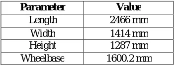
The previous year’s chassis was taken as the benchmark. It abided the rules and regulations as mentioned in the rulebook. FSAE rules have laid special emphasis on the driver safety in case of an accident. The car clears the technical inspection only if it adheres to these rules. However this chassis had various issues which had to be rectified. The race car was modelled in Pro-Engineering Wildfire V 4.0. Initially baseline dimensions like wheelbase, overall length, width and height were selected as mentioned in the Table 1. The location of the main hoop was decided considering pre-decided engine mounting points and drive shaft location so as to ensure adequate amount of space for drive train components and maximum allocation of space in the cockpit. Front bulkhead was located as per the length of manikin’s leg room. Front roll hoop and rear hoop were fixed at an optimum angle in such a way so as to accommodate suspension hard points.
Table 1: Pre-decided parameters of the chassis
Parameter Value
Length 2466 mm
Width 1414 mm
Height 1287 mm
A series of plane were made in Pro-E for the visualization of these locations. First the fixed elements like roll hoops, front bulkhead, suspension points and engine mounts were modelled for quicker iterations during the design. While deciding the roll hoop and bulkhead shape, length of the tubing was considered to reduce weight as they employ the thickest tubing. The engine mounting location was fixed so that the other components can be accurately placed in the rear compartment. The next step involved modelling variable connecting elements. To reduce weight, the number of these tubes was kept as minimum as possible. It resulted in the first model in Pro-E.
Various kinds of flaws were present in the previous year’s chassis which had caused a lot of problems in the functioning and handling of the vehicle. However suitable solutions to these flaws were accommodated while designing the new chassis. The various problems with the remedies incorporated are as follows:
A. Interference of the steering rack with the mounting of tandem master cylinder which resulted in a congested front compartment and involved tedious procedures while working on the brake and steering system. To overcome this problem, the mounting of the steering rack was placed slightly above the floor closer and the compartment size was marginally increased which created a significant gap to avoid interference.
B. Improper and excessive mountings were made to hold the engine which causing a lot of trouble to work in that compartment of the vehicle. Therefore, this time the engine was mounted using and additional link and a previously existing link to support the engine on just four mounting points.
C. Battery mounting was behind the driver seat which caused the problem of disassembling and assembling the seat every time to replace it. A special basket type mounting was provided on an already existing chassis member in the rear compartment to resolve this issue.
D. A heavy compromise was made with the driver safety due to improperly oriented seat, misaligned firewall and most rules of the chassis which qualified at the required limits. In order to correct it appropriate changes were made to accommodate manufacturing errors and suitable ergonomic considerations were included as explained in a later section.
E. Haphazard mounting for various components such as impact attenuator, brake fluid reservoir, pedal assembly mountings, panel mountings were overcome by using small sized laser cut mountings and fixed at calculated distances to overcome interferences.
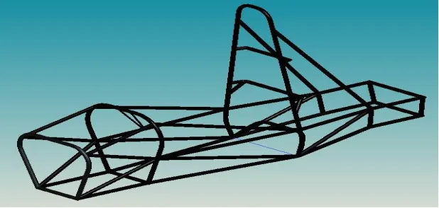
Figure 1: The final model of the designed chassis
Hyperworks to validate the design. Weak and ineffective links were improved by modifying their positions, resizing, adding new links, deleting unnecessary members etc. Repeated iterations in design followed by the analysis were performed to get the most optimal design. Final step in the modelling includes the assembly of all the parts along with the driver to check for various rules, regulations, interferences and clearances. The final chassis design has been shown in Figure 1.
IV. MATERIALSELECTION
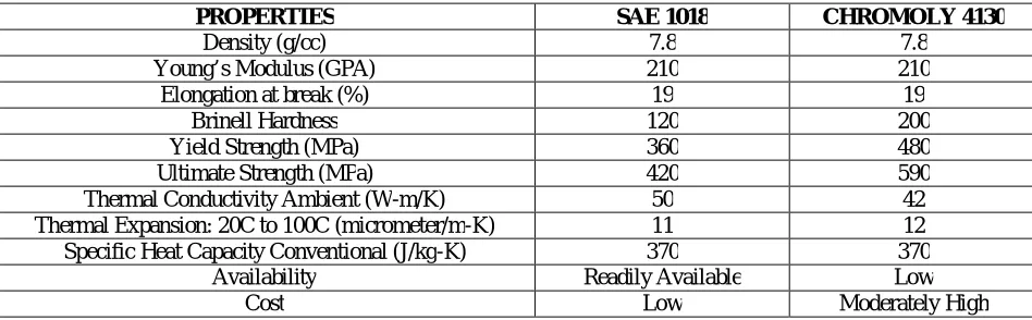
The material property of the chassis is an important criterion while designing and fabricating the vehicle. The chassis encounters various types of forces during motion. Hence, it should not deform or yield, be stiff enough to absorb vibrations, resist shocks and high temperatures. It should also be manufactured with ease within the existing constraints. The space frame chassis was preferred over the monocoque as it involves cost effective manufacturing using simple tools and rectification of damages despite being heavier. The two very commonly used materials for making the tubular chassis are Chromium Molybdenum steel (Chromoly 4130) and SAE-1018. Both these materials were analysed for different parameters as mentioned in Table 2 and finally it was decided to use SAE- 1018 because of several reasons.
PROPERTIES SAE 1018 CHROMOLY 4130
Density (g/cc) 7.8 7.8
Young’s Modulus (GPA) 210 210
Elongation at break (%) 19 19
Brinell Hardness 120 200
Yield Strength (MPa) 360 480
Ultimate Strength (MPa) 420 590
Thermal Conductivity Ambient (W-m/K) 50 42
Thermal Expansion: 20C to 100C (micrometer/m-K) 11 12 Specific Heat Capacity Conventional (J/kg-K) 370 370
Availability Readily Available Low
Cost Low Moderately High
Table 2: Comparison on the basis of various parameter between SAE 1018 and Chromoly 4130
SAE 1018 grade steel is better in terms of Thermal properties but weaker than Chromoly in terms of strength. However given the conditions in which the vehicle would operate, the strength provided by the SAE 1018 was adequate. Moreover the minimum tubing size is specified for various chassis parts which prevent the application of Chromoly tubes with a smaller wall thickness, so the benefit of weight savings cannot be obtained. An additional complexity when working with 4130 is the need to normalize the structure after welding.
Besides that Chromoly 4130 requires TIG welding which was not available for the fabrication of the vehicle. Its availability was low and cost moderately high. Hence, SAE 1018 turned out to be the most optimum choice for the existing constraints with the added benefits of being readily available, low cost and better thermal properties with adequate strength.
V. ERGONOMICCONSIDERATIONS
To make the vehicle ergonomically sound, all available drivers were fitted in mockup as well as the 95th percentile male template to determine all ergonomic variables. These include seating angle, elbow space, head height in relation to the front of the car, control operations (pedals, shifter and steering wheel) etc. For example, the seating position in the car was determined mainly from having the driver test different seat back angles in a plywood seat mockup.
Based on the following setup, the following conclusions were derived and incorporated in the design phase of the vehicle:
1. The cockpit was designed to give driver sufficient room for entering and exiting the car, as well as provide room for steering and shifting motion. It also included more than adequate space for egress.
2. Portion behind the front bulkhead was designed to accommodate aerodynamic features without affecting the visibility. A smooth increase from nose tip to end provides streamline body.
3. The front portion of the frame that is inside front roll hoop provides ample room for drivers with different leg lengths. Space between the two legs for steering shaft was also considered.
4. An increased cockpit length increases the bent angle at knees as a result of which the driver will feel no strain in thighs and pelvic area.
5. Special attention was made to the packaging of the pedal assemblies. This arrangement allowed the feet to rest above the steering rack mount, a position which is comfortable and safe.
6. Steering wheel was located in such a way that the driver could steer the wheel without hitting his legs while operating pedals.
7. To accommodate the seat and firewall, the shoulder harness mounting bars was designed in such a way that it gives a comfortable seating posture to the driver and place a bent firewall for driver safety.
8. Seat mounting and padding used on the seat facilitated driver’s visibility.
Values of few of the ergonomic variables used for consideration are mentioned in Table 3.
ERGONOMIC CONSIDERATIONS
Parameters Standard Range Design Value
Angle at elbows 125 to 140 degrees 135 degree
Angle at knees 120-150 degrees 130 degree
Angle at back 10 to 35 degrees 30 degree
Steering wheel diameter (mm) 254
Angle of steering wheel 43 degree
Table 3: Values of the various ergonomic parameters taken into consideration for the sound ergonomic design of the vehicle
VI. IMPACTANALYSISBYFINITEELEMENTALANALYSIS
Finite element analysis (FEA) is the modelling of products and systems in a virtual environment, for the purpose of
finding and solving potential (or existing) structural or performance issues. FEA is the practical application of the finite element method (FEM), which is used by engineers and scientist to mathematically model and numerically solve very complex structural, fluid, and multi-physics problems [2]
.
At the time of performing the analysis of the vehicle the exact weight was not known, therefore the weight of the vehicle with the driver was assumed to be 300 kg.
Front Impact (According to FMSVSS208): For frontal impact force calculations, we assume that our vehicle is colliding into a fixed rigid barrier. Collision is considered as perfectly plastic, therefore coefficient of resolution, e=0 and maximum impact force is directly calculated from the theory of impulse and momentum. As change in momentum of body is equal to impulse acting on it.
Change in momentum = m.vfinal - m.vinitial = F x ∆t
m = mass of the vehicle with driver vfinal = final velocity of the vehicle ( 0 m/s)
vinitial = initial velocity of the vehicle (27.78 m/s; the most
critical case assumed) F = impact force on the vehicle
∆t = time of collision = 0.18s (In automobile industries crash pulse is assumed to be between 0.15 to 0.20, hence we estimate the value of 0.18s)
F = 300 x (27.8 – 0)/ 0.18 = 46300 N
This load is distributed uniformly on the front bulkhead.
Side Impact (According to FMSVSS214): The direction of impacting vehicle is considered perpendicular to our vehicle for critical condition in side impact. Collision is assumed to be plastic. It is assumed the line of impact force directly passes through the centre of gravity of both the vehicles and maximum velocity is taken to be 22.22 m/s for critical condition.
m(b) = mass of vehicle B = 400 kg m(a) = mass of our vehicle A = 300 kg
v(a) = velocity of vehicle A = 0 (for critical case) v(b) = velocity of vehicle B = 22.22 m/s (maximum) v(c)= common velocity of point of impact at maximum compression (when impact force is maximum)
∆t = time of collision = 300 ms (NHTSA or FMVSS check injury criteria at 300 ms after the impact)
Since for maximum compression, impulse is equal and opposite in direction.
Impulse = F.∆t = m(a) x [v(c) – v(a)] = m(a).v(c) = m(b) x [v(c) – v(b)]
From the equation above, we get v(c)= m(b).v(b)/[m(a) + m(b)]
F = m(a).v(c)/∆t = 12690 N
The load is uniformly distributed on side members.
Table 4: Calculation of the loads during front impact and side impact on the vehicle
At the time of analysis, the torsional impact load, rollover impact load, bump impact load and rear impact load could not be determined, therefore to be on the safe side it was assumed that 3g (3 x acceleration due to gravity) load exists on the vehicle in all these conditions. The assumed value of g = 10 m/s2. Therefore, 3g = 30 m/s2 and load on the vehicle = mass x 3g = 300 x 30 = 9000 N.
Type of Load Description
Torsional Impact Load In case of torisonal impact, the load is applied on each side of the front suspension hard points but in vertically opposite directions. Hence, load at each node = 2250 N
Bump Impact Load The load is applied at 8 points; 4 on the front suspension hard points while the other 4 on the bottom most nodes of the front compartment which gives load on each node as 1125 N. Rollover Impact Load The direction of the loads during rollover is considered to be at
angle of 45 degree to the vertical plane of the vehicle. The load is divided at 4 points: 2 on the front hoop at the bracing points while 2 on the main hoop at the bracing points. Therefore, load at each node =2250N.
Rear Impact Load The rear impact load is uniformly distributed on the rear bulkhead.
On the basis of the application of the calculated loads in each case of the space frame chassis, the following results were obtained after the analysis as concluded in Table 6 below:
Type of Load Maximum Force (kN)
Maximum Equivalent Stress (MPa)
Maximum Displacement (mm)
Factor of Safety
Front Impact Load 46.3 206.6 7.47 1.47
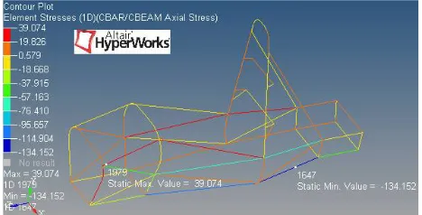
Side Impact Load 12.69 134.152 13.722 2.27
Torisonal Impact Load 9 214.143 33.484 1.42
Rollover Impact Load 9 38.51 4.373 7.92
Bump Impact Load 9 425.918 38. 863 0.72
Rear Impact Load 9 36.635 1.966 8.34
Table 6: Final results of the impact analysis after finite element analysis in Hyperworks
The outcomes of the application of various types of impact loads on the chassis were taken from the analysis performed in Altair Hyperworks. The most probable impact which can occur on the vehicle at the race track is the front impact, side impact, rollover impact and rear impact. The chance of the vehicle to suffer from a torisonal impact is slightly moderate while the bump impact is a very rare phenomenon. On the basis of the degree of severity of the impacts the vehicle can encounter on the track, we have adequate amount of factor of safety.
Figure 2: Displacement in the vehicle during front impact Figure 3: Stresses in the vehicle during front impact
The figures 2, 3, 4 and 5 give us the results of the impact analysis when the vehicle would be subjected to front and side impact. The maximum and minimum value of the displacement and stress in each of the case has been highlighted. Moreover the different displacements and stresses in the various regions of the space frame chassis have also been shown.
Similarly the figures 6, 7, 8 and 9 highlight the distribution of displacement and stresses in the various links of the space frame chassis if the vehicle was subjected to a rollover or torisonal impact. Their maximum and minimum values have also been mentioned at their respective location in the chassis
Figure 6: Displacement in the vehicle during rollover impact Figure 7: Stresses in the vehicle during rollover impact
Figure 8: Displacement in the vehicle during torsional impact Figure 9: Stresses in the vehicle during torsional impact
The figures 10, 11, 12 and 13 show the similar results of displacement and stress distributions along with their peak values on the application of the load during bump and rear impact evaluated in Altair Hyperworks.
Figure 12: Displacement in the vehicle during rear impact Figure 13: Stresses in the vehicle during rear impact
The simulation proved to be very vital in validating the designed space frame chassis and ensuring that the driver will be safe on the race track.
VII. CONCLUSION
The following conclusions were drawn while designing and analysing the developed space frame chassis:
1. The design was accurate complying fairly with the rules and regulations of the rulebook. It incorporated all the solutions of the problems faced by the previous year’s vehicle and the most optimal design fulfilling all the pre-requisite objectives was attained after sufficient periodic iterations.
2. The ergonomic considerations evaluated on the basis of mock setup and theoretical studies were fairly integrated into the design of space frame chassis.
3. SAE 1018 was selected as the material for making the chassis as it turned out to be the most optimal choice among the alternatives abiding the constraints and meeting the requirements.
4. The maximum stresses, displacement and factor of safety of the vehicle have been determined by loading the vehicle under various types of impacts.
REFERENCES
[1] SUPRA SAEINDIA Student Formula Rulebook 2015.
[2] FEA: https://www.plm.automation.siemens.com/en_us/plm/fea.shtml (Accessed 05/04/16, 21:50).
[3] D. Lavanya, G.Guru Mahesh, V.Ajay and DR. C.Yuvraj, “Design and analysis of a single seater car chassis frame”, IJRAME, Vol. 2 Issue 8, pp. 12-23, August 2014.