Available online:
http://edupediapublications.org/journals/index.php/IJR/
P a g e | 456Development and Performance evaluation of IRIS recognition
in the presence of occluded region
K.Sreedevi & K.Padma priya
Research Associate ,Dept. of Electronics and Communication Engineering ,UCEK(A),
JNTUK,Kakinada, Andhra Pradesh, India
1Professor ,Dept. of Electronics and Communication Engineering ,UCEK(A),
JNTUK,Kakinada,
Andhra Pradesh, India2Abstract:
For secure, and reliable authentication process as compared to other security systems such as password or any other biometric systems, Iris recognition is computationally more efficient. Conventional iris segmentation methods gives good results only for ideal iris images. The segmentation accuracy has influence on the performance of non-ideal iris images. Iris recognition system comprises of Iris segmentation, Normalization, Feature extraction and Matching. IRIS databases like CASIA V1.0, MMU2, UBIRIS V1 and UBIRIS V2 are used for experimental results. Image segmentation using active contour method, the coarse parameters of iris, pupil radius will be known. The normalization process involves unwrapping the iris and converting it into the rectangular image as proposed by Daugman. The normalized iris image converted to iris code using feature extraction. Hamming distance classifier is to matching the two iris codes. The Iris images are accessed through serial communication from personal computer. The four steps are carried out for iris recognition system with the help of personal computer, controller unit (ARDUINO UNO R3), LCD display and servo motor (for activation). The IRIS recognition helps in authenticating a system.
Key words:
Active contour, segmentation, inpatinting, pupil segmentation, iris segmentation, active contour, normalization.
1.
Introduction
A reliable personal identification infrastructure is essential for controlling the access to secure areas and also used for civil and forensic applications, including border crossings, criminal investigations, systems for voter registration, verification and duplication checking, passport issuance and other national-scale projects. Biometric techniques such as faces, finger prints, palms, and eyes have many applications in surveillance and security. The human iris recognition technique has more importance compared to other computer vision-based techniques which recognize several features like faces, finger prints, palms and etc., [1]. The iris is very unique that every two persons have different iris patterns. Identical twins also have unique iris pattern and even same person’s left and right eye iris patterns are unique and contain
high level of randomness in the entire human population. The more importance of iris pattern is due to its accuracy, reliability, and noninvasive characteristics.
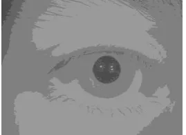
The authentication of a person is based on the physiological or behavioural characteristics. Biometric characteristics are distinctive and it cannot be forgotten or lost [2]. Hence physical presence is very important for identification. Iris is the coloured part of eye shown in Figure1, pupil is black part of eye, which is unwanted part for recognition. Sclera is the white part of eye. Localization of pupil and iris need to be carried out for segmentation.
Figure 1. A typical image of human iris.
2.
Iris recognition system
2.1. Pupil Localization
Segmentation plays a crucial role in iris recognition, which is carried out in two steps they are pupil and iris localization. There are several types of iris databases, classified based on illumination of light for example images captured under Near Infrared (NIR) and visible light. There will be high contrast between the pupil and iris in the case of image captured under NIR light. Pupil segmentation comprised of 1) reflection removal 2) mean shift 3) obtaining the coarse parameters of the pupil.
2.1.1. Reflection removal:
Available online:
http://edupediapublications.org/journals/index.php/IJR/
P a g e | 457individual threshold for every pixel within a window 30×30. The average filter is applied to the every pixel of the image. This smoothened image is subtracted from original image to get the reflections image as shown in Figure 2. This reflections image converted to binary image. The binary image is different from reflections image as binary image only contains the light reflections as shown in Figure 3. The reflections are removed with help of inpainting. Inpainting is the removal of occlusions in an image. At first the area of missing or damaged is identified, which is termed as mask image. Here binary reflection map is the mask image for inpainting and it is a binary image. The diffusion is carried out after finding the missing or damaged area [3].
Figure 2. Steps of reflection removal. (a) Smoothened image. (b) Reflections image.
Figure 3. Binary reflection map.
The inpainting procedure can be done by an isotropic diffusion process, which changes the pixel value based on the neighborhood and kernel. There are different kernels can be used for inpainting. The two kernels that are used
a b a
b b
a b a
A 0
c c c
c c
c c c
B 0
Where a=0.073235, b=0.176765, c=0.125.
2.1.2. Mean shift:
Mean shift is helpful for segmentation of pupil [4]. A uniform kernel is used for mean shift. The eyelashes are found in the output image, which are need to be removed. Hence only the pupil is retained in the image as shown in Figure 4. The kernel bandwidth parameters (hs, hr) are (4, 3), which are helpful to control the number of clusters.
2.1.3 The coarse parameters of the pupil:
The only pupil is obtained by adaptive thresholding. The required object is isolated from the background with threshold, which is obtained through histogram. This method is based upon Otsu’s method [5].
Figure 4. Mean shift segmentation.
The histogram shows two peaks, with a deep valley in between them representing object and background. Initially the mean of the image is considered as threshold. The two different images are created. The pixels which are greater than the threshold (mean of the image) are comes under one image, the remaining pixels are comes under the second image. Two separate means are obtained for the two images respectively. The main threshold is average of two image’s mean. The eyelashes are isolated by morphological dilation. The pupil is retained in the resultant image after applying Otsu method as shown in Figure 5.
Figure 5. Pupil extraction using Otsu method
In the process of finding coarse parameters of pupil, eyelashes are removed using Morphological dilation. In a morphological operation, the every pixel in the output image is replaced by a new pixel. The replacement is done by finding maximum value in the neighborhood of the every pixel in the image.
2.2. IRIS SEGMENTATION
This is essential to find out the coarse parameters of iris. Active contour model is used in three ways. They are snake active contour, Gradient Vector Flow, existing Active contour model.
2.2.1. Snake active contour model:
Available online:
http://edupediapublications.org/journals/index.php/IJR/
P a g e | 458N+1 vertices(snaxels or snake pixels)
k k
k
x
y
v
,
, 0kN. Where k is the length of the snake k[0,1]. The contour will closed by thecondition v0 vN. Every vertex is moved to new
position which has minimum energy(E0) in its 33
neighborhood as shown in Figure 6 [9].
Figure 6. Nearest neighborhood of size 33for searching minimum energy for vertex
v
i. Here the minimum energy is observed in a position below andto the left of the current pixel position, in this example the new position of the pixel is (-1,1).
As shwon above, for every pixel the minimum energy is calculated (2). The snake energy is defined as
v dk E
v dk EEsnake
k
ext k1
0
1
0
int (1)
Internal energy is combination of continuity energy
Econt
and curvature energy
Ecurv
[9].curv
cont E
E
Eint (2)
2
2
int 2 1 k v k v v
E k k k k kk (3)
2 , * ,y I x y xG v
Eext k (4)
This energy
E0 is summation of internal and external energies (1).
'
, ' , ' , 1 0min
2 j ext i j curv i j cont i m j E E EE
(5)
Here the snake pixels are taken from the user with help of cursor as shown in Figure 7(a). The iris is localised using snake active contour as shown in Figure 7(b).
Figure 7. Snake active contour model. (a) Intial contour of snake (b) Iris localisation.
2.2.2. Gradient Vector Flow Active Contour:
Xu and Prince [10] proposed the Gradient Vector Flow (GVF) active contour model. The GVF snake is defined by a contour vk
xk,yk
. This will be satisfied by below mentioned Euler equation.0
v V
vkk kkkk
(6) Where V
x,y (u
x,y,vx,y)is the vector field, which is another form of external energy
Eext of snake contour model. As the previous model, the internal force of GVF is also combination of elastic and bending forces. The edge map f
x,y of the image is shown in (7).
2, * ,
,y G x y I x y x
f (7) The vector filed V is the energy minimization as shown in (8).
ux uy vx vy
f V f dxdy2 2
2 2 2
2
(8)where ux,uy,vx, and vyare the partial derivatives of
x yu , and v
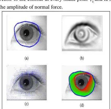
x,y in the x and y directions. GVF also has drawback in stopping at spurious edges. The resultant images of GVF are shown in Figure 8.2.2.3.Existing Active Contour Model:
The previous conventional methods do not stop at desired boundary of iris. This existing method localizes the iris with help of initial mask. An internal pressure force is additionally added in this new model to the external force of GVF (9).
0
kkkk k
kk v V Kn
v
(9) The internal pressure force acts in direction normal to the curve to push outside. Where nkis the unit normal vector to the contour at every snake pixel vkand K is the amplitude of normal force.
Figure 8. GVF model. (a) The iris image with initial contour (b) The external energy (c) The external force
Available online:
http://edupediapublications.org/journals/index.php/IJR/
P a g e | 459The unit normal vector of a contour is perpendicular to the curve at that position. This normal vector is perpendicular to the tangent vector at same point. The normal vector is the ratio between tangent vector of a curve and its amplitude (10).
s Ts T nk '
'
(10)
T(s) is the unit tangent vector, T'
s is tangent’s derivative and T' s is the Euclidean norm of tangent. The pressure force is same as the adaptive force [5].The result image of existing active contour method shown in Figure 9.Figure 9. Iris localization using proposed method
2.3.Normalization
This step is followed by segmentation of pupil and iris. Normalization is nothing but the unwarping of iris (circular part) into dimensionless polar coordinates (rectangular image) which is proposed by Daugman [11]. The resultant normalized image is shown in Figure 10.
Figure 10. Normalization of iris
2.4.Modified method of Feature Extraction
and Template matching
As per the existing method, the normalized image is convolved with 1-D log-Gabor filter [12]. The template image is shown in Figure 11.
Figure 11. Template of Normalized iris image
In the modified method of feature extraction different levels of decomposition is used. Out of 3 different levels the fourth level decomposition gives the best result, because the execution time for this level is less compared to the other levels. Hamming distance is used to compare the two templates of iris images.
Two iris templates of same person has the hamming distance of 0.32 [2]. The threshold for measuring is obtained from the experimental results.
If HD<= Threshold, then Match successful. If HD> Threshold, then match unsuccessful
which means the two templates are belong to two different persons or same person’s left and right iris templates.
3.
Hardware Implementation
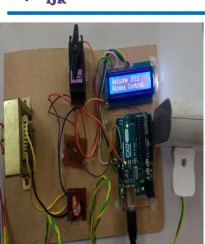
All experiments were done under the MATLAB and Arduino io environment. Initially MATLAB supporting package is installed in computer. Here the controller unit is Arduino Uno R3. Authenticated systems are becoming smarter and well developed by using these type of technologies. Iris recognition system authenticates a person, who tries to activate the system. As mentioned above iris recognition system is used for activation (Rotating servo motor). The block diagram is shown in Figure 12. Initially program is uploaded to controller unit, which helps to read the data from computer (MATLAB) and shows the information to be displayed on the LCD display. The hardware implementation is shown in Figure 13.
Available online:
http://edupediapublications.org/journals/index.php/IJR/
P a g e | 460Figure 13. Hardware implementation of Iris recognition system
4.
Results and Discussion
For modified method and existing method the results are compared as shown in TABLE I. The comparison is done between 2 persons images. For each person 5 different instances iris images are taken.
TABLE I. The comparison between existing and modified methods of feature extraction.
Method Rate of recognition
Existing feature extraction 86.67%
Modified feature extraction
93.33%
The results are obtained for images of two different persons. For each person 5 different iris images are considered. The comparison of results of feature extraction are shown in Figure 12 and TABLE II.
TABLE II. The comparison between different levels of feature extraction.
No: of levels for wavelet decomposition
Time taken for each method
3rd level 918ms
4th level 757ms
5th level 844ms
Figure 12. Comparison between the time taken for different levels in feature extraction
Iris recognition system compares the person’s iris templates and authenticates based on the measurement of hamming distance. If hamming distance (HD) <= 0.32 tells that Irises are matched and hamming distance > 0.32 means that match not found between the two iris templates [2]. From the observed results of modified method the threshold is 6460. This measuring threshold decides whether the iris templates are matched or not. The execution of MATLAB followed by the serial communication between the computer and controller unit. Whenever the matched condition occurs the LCD display shows that “IRIS is matched”, conversely LCD display shows that “Match not found”. At the same time servo motor rotates when Iris matched condition occurs. The servo motor will be rotated whenever the iris matched condition occurs. Conversely the motor will not rotate for unmatched condition. The hardware implimentation of iris recognition system is shown in Figure 13.
5.
Conclusion
Available online:
http://edupediapublications.org/journals/index.php/IJR/
P a g e | 461Figure 13. Hardware implimentation of database dependent Iris recognition system
6. References
[1] Nithyanandam.S, Gayathri.K.S, Priyadarshini P.L.K,” A New IRIS Normalization Process For Recognition System With Cryptographic Techniques”. IJCSI International Journal of Computer Science Issues, Vol. 8, Issue 4, No 1, July 2011 ISSN (Online): 1694-0814.
[2] Vanaja Roselin.E.C, “Pupil detection and feature extraction algorithm for Iris recognition”. AMO-Advanced Modeling and Optimization, Volume 15, Number 2, 2013.
[3] Manuel M. Oliveira, Brian Bowen, Richard McKenna, Yu-Sung Chang,” Fast Digital Image Inpainting”.Appeared in the Proceedings of the International Conference on Visualization, Imaging and Image Processing (VIIP 2001), Marbella, Spain.September 3-5,2001.
[4] D. Comaniciu and P. Meer, “Mean shift: A robust approach toward feature space analysis,” IEEE Trans. Pattern Anal. Mach. Intell., vol. 24,no. 5, pp. 603–619, May 2002. [5] N. Otsu, “A threshold selection method from
gray-levelhistograms,”IEEE Trans. Syst., Man, Cybern., vol. 9, no. 1, pp. 62–66, Jan. 1979.
[6] M. Kass, A. Witkin, and D. Terzopoulos, “Snakes: Active contour models,” Int. J. Comput. Vis., vol. 1, no. 4, pp. 321– 331, 1988.
[7] Kass M, Witkin A, Terzopoulos D.Snakes: active contour models. Int J Comput Vision formulation. Pattern Recogn Lett 2005; 26(13):2042-2051.
[8] Yang Y, Tannenbaum A, Giddens D, Coulter W.Knowledge-based 3D segmentation and reconstruction of coronary arteries using CT images. Conf Proc IEEE Eng Med Biol Soc 2004; 3:1664-1666.
[9] M.Haidekker, Deformable Models and Active Contours. Canada: Wiley, 2011, pp. 173-210.
[10] C. Xu and J. L. Prince, “Snakes, shapes, and gradient vector flow,” IEEE Trans. Image Process., vol. 7, no. 3, pp. 359– 369, Mar. 1998.
[11] J. G. Daugman, “High confidence visual recognition of persons by a test of statistical independence,” IEEE Trans. Pattern Anal. Mach. Intell., vol. 15, no. 11, pp. 1148–1161, Nov. 1993.
[12] L. Masek and P. Kovesi, “MATLAB source code for a biometric identification system based on iris patterns,” School Comput. Sci. Softw. Eng., Univ. Western Australia, Crawley, WA, Australia, 2003. Accessed on Apr. 2016. [Online].Available:http://www.peterkovesi.com/studentprojec ts/libor/sourcecode.html.
[13] Chinese Academy of Sciences Institute of Automation.
CASIA Iris Image Database. Accessed on Feb. 2016. [Online].Available:http://biometrics.idealtest.org/dbDetailFor User.do?id=4.
[14] H. Proenca, S. Filipe, R. Santos, J. Oliveira, and L. A. Alexandre,“The UBIRIS.v2: A database of visible wavelength iris images captured on-the-move and at-a-distance,” IEEE Trans. Pattern Anal.Mach. Intell., vol. 32, no. 8, pp. 1529–1535, Aug. 2010.