A Hybrid Method for the Coupling Analysis of Multiconductor
Transmission Lines Excited by Dipole Antenna
Zhihong Ye1, *, Dan Gou1, Jianjian Zhou1, and Xuesong Meng2
Abstract—This paper presents a hybrid method consisting of thin wire FDTD method and transmission line (TL) equations to be used for the coupling analysis of multiconductor transmission lines (MTLs) excited by a dipole antenna. In this method, the thin wire FDTD method is used to build the structure of the dipole antenna and obtain the radiation electromagnetic fields surrounding the MTLs, which are introduced into the TL equations as the distribution sources. The TL equations are utilized to model the coupling of the radiation electromagnetic fields to the MTLs, which are discrete by the scheme of the FDTD method to obtain the transient voltage and current responses on the lines and terminal loads. The accuracy and efficiency of this method have been verified by comparing with the commercial simulation software CST via one case. Moreover, the influences of the frequencies and polarization of the dipole antenna and the heights of the MTLs on the coupling of MTLs are analyzed.
1. INTRODUCTION
With the working frequencies of electronic systems becoming higher and higher, some devices in the electronic systems should generate electromagnetic radiation inevitably. These radiation electromagnetic waves should couple interference signals on the transmission lines in the electronic system and then penetrate into the terminal circuits to disturb or damage the pivotal elements of the circuits. Therefore, it is significant to simulate and analyze the coupling of radiation electromagnetic waves to the transmission lines.
Because the structures of electronic systems are complex, it is difficult to obtain waveforms of the radiation electromagnetic waves created by the electronic devices directly, while the working signals or interference signals derived from the devices are propagating through the transmission lines and then radiating to the outer space to form the radiation waves. Hence, the transmission lines should be seen as antennas naturally. In this paper, a transmission line is assumed as a dipole antenna, and then the coupling of the radiation electromagnetic fields created by the dipole antenna to transmission lines should be studied.
At present, several efficient field-to-line coupling methods have been proposed, such as Baum-Liu-Tesche (BLT) equation, FDTD-SPICE method, and FDTD-TL method. However, the BLT equation [1–4] is a frequency domain method, and it is not suitable for the coupling analysis of transmission lines excited by ambient broadband wave. The FDTD-SPICE method [5–11] is a time domain method, while this method needs a number of theoretical derivations, and the calculation of the electromagnetic fields and transient responses on the transmission lines and loads are separated. The FDTD-TL method [12–14] is the previous research of our group. In this method, the FDTD method is used to compute the excitation fields of transmission lines, and the coupling model of ambient wave to transmission lines is established via TL equations. The biggest advantage of the FDTD-TL method compared with other
Received 26 August 2018, Accepted 25 September 2018, Scheduled 18 November 2018
* Corresponding author: Zhihong Ye (yezh@cqupt.edu.cn).
1 School of Communication and Information Engineering, Chongqing University of Posts and Telecommunications, Chongqing 400065,
32 Ye et al.
methods is that it can realize the synchronous computations of the electromagnetic fields and transient responses on the lines and loads. However, the incident waves in these methods are assumed as plane waves.
Therefore, this paper presents a hybrid method consisting of the FDTD-TL method and thin wire FDTD method to be used for the coupling analysis of multi-conductor transmission lines excited by a dipole antenna rapidly. This presented method should realize synchronous computations of the radiation electromagnetic fields of the dipole antenna and transient responses on transmission lines and loads greatly.
This paper is organized as follows. The theory of the hybrid method is introduced in Section 2. In Section 3, the accuracy and efficiency of this hybrid method are demonstrated via one case firstly, and then the influences of the frequencies and polarization of the dipole antenna and the heights of the MTLs on the coupling of MTLs are analyzed. Conclusions are given in Section 4.
2. THEORY OF THE HYBRID METHOD
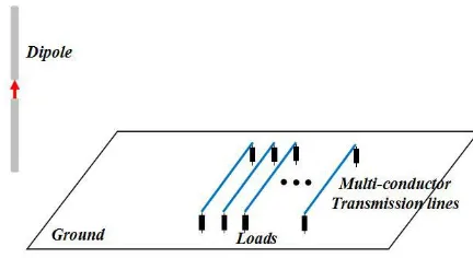
The model of multiconductor transmission lines excited by a dipole antenna is shown in Fig. 1. The dipole consists of two metal columns and is fed by a current source. The MTLs are located on the ground, which are parallel to the ground and terminated with loads.
The coupling analysis of the MTLs excited by the dipole antenna should be decomposed into two parts. One part is the calculation of the radiation electromagnetic fields of the dipole antenna, which can be achieved by the thin wire FDTD method. The other part is the coupling of the radiation electromagnetic fields to the MTLs, which should be modeled by the TL equations.
Figure 1. The coupling model of multiconductor transmission lines excited by a dipole antenna.
2.1. The Radiation Electromagnetic Field Calculation of the Dipole Antenna
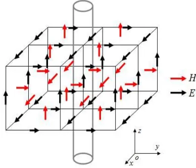
Because the FDTD method is limited to the minimum structure of the target, the grid of the FDTD method used for the dipole antenna should be small, which needs to occupy many computation memories. Considering that the cross sections of the metal columns of the dipole antenna are smaller than that of the FDTD grid, the thin wire FDTD method can be used to avoid modeling the structure of the dipole antenna directly and save some computation memories. The grid division of the thin wire FDTD for one column of the dipole antenna is shown in Fig. 2.
The magnetic fields in the Yee cell adjacent to the columns of the dipole antenna are computed by the loop integral of the adjacent electric fields according to the Faraday’s law, which can be expressed as
−
lE·dl=μ0
∂ ∂t
SH·dS (1)
Figure 2. The grid division of one column of the dipole antenna.
2.2. The Coupling of Radiation Electromagnetic Fields to the MTLs
The description of the TL equations for the coupling of the radiation electromagnetic fields to the MTLs can be expressed as
∂
∂xV(x, t) +L ∂
∂tI(x, t) = VF(x, t) (2)
∂
∂xI(x, t) +C ∂
∂tV(x, t) = IF(x, t) (3)
where L and Cdenote the per-unit-length inductance and capacitance matrices of transmission lines, respectively. V(x, t) and I(x, t) represent the voltage and current vectors of transmission lines, respectively. VF(x, t) and IF(x, t) are distributed voltage and current source vectors, respectively, which can be expressed as
VF(x, t) = − ∂
∂xET (x, t) +EL(x, t) (4)
IF(x, t) = −C∂
∂tET(x, t) (5)
ET(x, t) and EL(x, t) can be expressed as
ET (x, t) =
h
0
eexy (x, y, z, t)dy (6)
EL(x, t) = eexx (x, h, z, t)−eexx (x,0, z, t) (7)
whereeexy and eexx are the incident electric field components vertical to the transmission lines and along the position of the transmission lines and the ground, respectively, which are computed by the thin wire FDTD method. Here, the electric fields on the ground are zero, when the ground is assumed as perfect conductor (PEC) plane.
When the distances of the MTLs to the ground are electrically small compared with the wavelength, the radiation of the MTLs should be neglected [7]. The distribution voltage and current sourcesET(x, t) and EL(x, t) are not relevant to the scattering fields of transmission lines. Therefore, the transmission lines should be removed when calculating the radiation electromagnetic fields of the dipole antenna.
34 Ye et al.
3. NUMERICAL SIMULATION
In this section, the accuracy and efficiency of this presented method are verified by comparing with the commercial simulation software CST via one case about five transmission lines on the ground excited by a dipole antenna firstly. Then the influences of the frequencies and polarization of the dipole antenna and the heights of the MTLs on the coupling of the MTLs are analyzed.
3.1. Verification of the Hybrid Method
The model of the five transmission lines on the ground excited by a dipole antenna is shown in Fig. 3. The ground is assumed as PEC with the dimension Lc×Wc = 40 cm×80 cm. The five transmission
lines are located on the ground with length l = 60 cm, height h = 1 cm, radius r = 1 mm, and distance d = 1 cm. The terminal loads of the MTLs are R1 = R2 = R3 = R4 = R5 = 50 Ω and
R6 =R7 =R8 =R9 =R10 = 100 Ω, respectively. The columns of the dipole antenna are seen as PEC
with length Ls= 8 cm and radius 3 mm. The height and distance of the dipole antenna to the ground are Hs = 2 cm and Ds = 10 cm, respectively. The feed current of the dipole antenna is a sine wave, which can be expressed asJ(t) = sin(2πf t), wheref = 1.0 GHz. The hybrid method is used to compute the transient responses on the terminal loads of the MTLs by comparing with the simulation software CST.
The transient voltages on the loadsR2 andR9computed by the hybrid method and CST are shown
in Figs. 4(a) and (b), respectively. It can be seen that the results computed by the hybrid method and CST are in good agreement.
Figure 3. The model of five transmission lines on the ground excited by a dipole antenna.
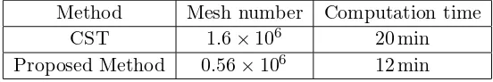
To verify the efficiency of this proposed method, the mesh number and computation time cost by the two methods are shown in Table 1. It is shown that the meshes and computation time needed by the hybrid method should be much less than that used by the CST software, because the MTLs should not be meshed in the proposed method.
Table 1. The mesh number and computation time needed by the two methods.
Method Mesh number Computation time
CST 1.6×10⁶ 20 min
(a) (b)
Figure 4. The voltage responses on the terminal loads of the MTLs. (a) The voltage responses on the loadR2. (b) The voltage responses on the loadR9.
3.2. The Coupling Analysis of the MTLs Excited by the Dipole Antenna
This section will use the hybrid method to analyze the coupling of radiation electromagnetic fields to the MTLs with different frequencies and polarization of the dipole antenna and different heights of the MTLs, respectively. Generally, the impedance on the port of the circuit is 50 Ω; therefore, the terminal loads of the MTLs are all set to 50 Ω.
3.2.1. Different Frequencies of the Dipole
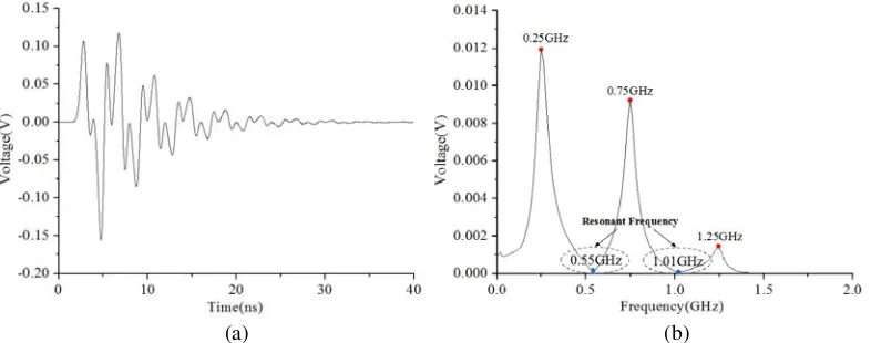
Firstly, the hybrid method is used to compute the responses on the MTLs excited by different frequencies of the dipole antenna. To better analyze the influence of the frequency of the dipole on the coupling of the MTLs, the feed current is changed to a Gaussian pulse, which can be expressed as J(t) = exp(−4π(t−t0)/τ), where τ = 2 ns andt0 = 1.6 ns.
The voltage response on the load R8 is shown in Fig. 5. It can be seen from Fig. 5(b) that the
voltage response should have several resonant frequencies, which are 0.55 GHz and 1.01 GHz. It means that when the frequencies of the interference signals are at these resonant frequencies, the voltages coupled to the lines should be small.
To further verify this conclusion, the coupling of the MTLs is excited by the dipole antenna with
(a) (b)
Figure 5. The voltages on load R8 with the dipole antenna fed by the Gaussian pulse current. (a)
36 Ye et al.
Figure 6. The voltages on loadR8 with different frequencies of the dipole antenna.
three frequencies, i.e., 0.75 GHz, 1.0 GHz, and 1.25 GHz, respectively. The voltage responses on the load R8 with different frequencies of the dipole antenna are shown in Fig. 6. We can see that the value for
1.0 GHz are much smaller than that of 0.75 GHz and 1.25 GHz. Therefore, we can draw a conclusion that one efficient way to suppress the electromagnetic interference of the devices in the electronic system is that the working frequencies of the devices should be or close to the resonant frequencies of the MTLs.
3.2.2. Different Polarization of the Dipole
Then, the hybrid method is used to compute the responses on the MTLs excited by different polarization of the dipole antenna. Here, a sine wave with frequency 1 GHz is used as the feed current of the dipole antenna.
It can be seen from Fig. 7 that the voltage on load R8 excited by the vertical polarization of
the dipole antenna should be much larger than that by horizontal polarization of the dipole antenna. Because the horizontally polarized dipole antenna should produce a negative mirror dipole through the ground, and then the electromagnetic fields above the ground should be attenuated.
Figure 7. The voltages on loadR8 with different
polarization of the dipole antenna.
Figure 8. The voltages on loadR8 with different
heights of the MTLs.
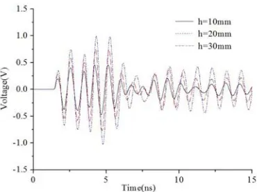
3.2.3. Different Heights of the MTLs
Finally, the hybrid method is used to compute the responses on the terminal loads of the MTLs with different heights, i.e., 10 mm, 20 mm, and 30 mm, respectively. The feed current of the dipole antenna is also a sine wave with frequency 1 GHz. The voltage responses on the load R8 are shown in Fig. 8. It
the values of the responses on the loads are decreased with the decrease of the heights of the MTLs. Therefore, the other way to suppress the electromagnetic interference of the devices in electronic system is that the MTLs should be closed to the ground.
4. CONCLUSION
This paper presents an efficient hybrid method consisting of FDTD-TL method and thin wire FDTD method, which can be well applied to the coupling analysis of multiconductor transmission lines on the ground excited by the dipole antenna rapidly. In this method, the thin wire FDTD method is used to compute the radiation electromagnetic fields of the dipole antenna without modeling the structure of the dipole directly. And the transmission line equations are utilized to build the coupling model of the radiation electromagnetic fields of the dipole antenna to the MTLs. Moreover, this hybrid method can realize the synchronous computations of the radiation electromagnetic fields of the dipole antenna and transient responses on the lines and loads.
The accuracy and efficiency of this hybrid method have been verified via the coupling analysis of five transmission lines on the ground excited by a dipole antenna. The results computed by the hybrid method agree well with that computed by the CST software. Meanwhile, the meshes and computation time cost by the hybrid method should be much less than the CST software, since the structure of the MTL does not need to be meshed in the proposed method. In addition, the influences of the frequency and polarization of the dipole antenna and the heights of the MTLs on the coupling of the radiation electromagnetic fields to the MTLs are analyzed. The results of this paper will provide technical approaches and theoretical basis for the electromagnetic interference analysis of the devices in electronic system.
ACKNOWLEDGMENT
This work was supported by the National Natural Science Foundation of China (Grant No. 61701057), the Chongqing Research Program of Basic Research and Frontier Technology (Grant No. cstc2017jcyjAX0345), and the Science and Technology Research Program of Chongqing Municipal Education Commission (Grant No. KJ1704082).
REFERENCES
1. Agrawal, A. K., et al., “Transient response of multiconductor transmission lines excited by a nonuniform electromagnetic field,” IEEE Transactions on Electromagnetic Compatibility, Vol. 22, No. 2, 119–129, 1980.
2. Tesche, F. M. and C. M. Butler, “On the addition of EM field propagation and coupling effects in the BLT equation,”Interaction Notes, No. 588, 1–43, 2003.
3. Xu, Q. X. and Y. Z. Xie, “The transient response of discontinuous MTL based on BLT equation,”
7th Asia-Pacific Conference on Environmental Electromagnetics (CEEM), 411–413, 2015.
4. Du, J. K., S. M. Hwang, J. W. Ahn, and J. G. Yook, “Analysis of coupling effects to PCBs inside waveguide using the modified BLT equation and full-wave analysis,”IEEE Transactions on Microwave Theory and Techniques, Vol. 61, No. 10, 3514–3523, 2013.
5. Paul, C. R., “A SPICE model for multiconductor transmission lines excited by an incident electromagnetic field,” IEEE Transactions on Electromagnetic Compatibility, Vol. 36, No. 4, 342– 354, 1994.
6. Erdin, I., A. Dounavis, and R. Achar, “A SPICE model for incident field coupling to lossy multiconductor transmission lines,”IEEE Transactions on Electromagnetic Compatibility, Vol. 43, No. 4, 485–494, 2001.
38 Ye et al.
8. Paul, C. R., “A SPICE model for multiconductor transmission lines excited by an incident electromagnetic field,” IEEE Transactions on Electromagnetic Compatibility, Vol. 36, No. 4, 342– 354, 2009.
9. Xie, H. Y., J. G. Wang, R. Y. Fan, and Y. N. Liu, “SPICE models to analyze radiated and conducted susceptibilities of shielded coaxial cables,” IEEE Transactions on Electromagnetic Compatibility, Vol. 52, No. 1, 215–222, 2010.
10. Xie, H. Y., J. G. Wang, Y. Li, and H. F. Xia, “Efficient evaluation of multiconductor transmission lines with random translation over ground under a plane wave,” IEEE Transactions on Electromagnetic Compatibility, Vol. 56, No. 6, 1623–1629, 2014.
11. Xie, H. Y., J. G. Wang, R. Y. Fan, and Y. N. Liu, “SPICE models for prediction of disturbances induced by nonuniform fields on shielded cables,” IEEE Transactions on Electromagnetic Compatibility, Vol. 53, No. 1, 185–192, 2011.
12. Ye, Z. H., C. Liao, X. Z. Xiong, and M. Zhang, “The research and application of a novel time domain hybrid method for EMI analysis of a shielded device with lumped circuit,” IEEE Transactions on Electromagnetic Compatibility, Vol. 58, No. 4, 964–970, 2016.
13. Ye, Z. H., X.-Z. Xiong, C. Liao, and Y. Li, “A hybrid method for electromagnetic coupling problems of transmission lines in cavity based on FDTD method and transmission line equation,” Progress In Electromagnetic Research M, Vol. 42, 85–93, 2015.
14. Ye, Z. H., C. Liao, X. Z. Xiong, and M. Zhang, “A hybrid method combining the novel TD-SC technique and FDTD method for the EMI analysis of transmission line network,” IEEE Transactions on Electromagnetic Compatibility, Vol. 58, No. 4, 1211–1217, 2017.