A Hybrid Method for Electromagnetic Coupling Problems of
Transmission Lines in Cavity Based on FDTD Method
and Transmission Line Equation
Zhihong Ye*, Xiangzheng Xiong, Cheng Liao, and Yong Li
Abstract—A time domain hybrid method is presented for efficiently solving the electromagnetic coupling problems of transmission lines in cavity. The proposed method is based on the finite-difference time-domain (FDTD) method and transmission line (TL) equations (FDTD-TL), which can achieve a strong synergism on the computations of field and circuit. The FDTD method with an auto mesh generation technique is employed to obtain the electric fields of transmission lines excited by an incident wave from the outside of the cavity. The electric fields are introduced into the TL equations as additional voltage sources at each time step of FDTD method. The current and voltage responses of terminal loads can be obtained by the TL equations. Two examples are presented to demonstrate the correctness of this method. The high efficiency of this hybrid method is verified by comparing the computation time with the traditional method.
1. INTRODUCTION
With the development of microelectronic technique, the integration level of electronic systems is becoming higher and higher. However, some high power electromagnetic pulses, such as nuclear electromagnetic pulse (NEMP), high power microwave (HPM), can penetrate into the shielding cavity of electronic system via its slots [1–5], and excite currents on the transmission lines. That will cause unexpected responses at the terminators of transmission lines.
There have been several methods applied to compute the coupling problems of transmission lines in cavity, such as Baum-Liu-Tesche (BLT) equation, finite difference time domain (FDTD) method, etc. The traditional BLT equation is a frequency domain method [6], and the transient BLT equation is developed to obtain time domain solutions [7–10], which calls for costly temporal convolution. The FDTD method is a popular time domain method [11–15]; however, its spatial step is limited by the highest interested frequency of excitation pulse and the minimum size of the computational model. Therefore, the mesh number of FDTD would be huge when the simulation model is tiny transmission lines in a cavity, which indicates large memory requirements and computation time.
Some hybrid FDTD and circuit simulation methods were proposed [16–18]. The FDTD method is used to compute excited fields of transmission lines, and the circuit simulation is used to compute responses on terminal loads of transmission lines. However, the solving process of field and circuit is handled separately.
This paper presents a hybrid FDTD-TL method to analyze the responses of the unshielded and shielded transmission lines in a cavity efficiently. The hybrid method achieves the synchronous calculation of electromagnetic fields and circuit responses. The FDTD method combined with an auto mesh generator is employed to model the cavity without transmission lines and the electric fields on
Received 26 March 2015, Accepted 21 May 2015, Scheduled 22 May 2015 * Corresponding author: Zhihong Ye (zhihongye love@163.com).
the transmission lines, which is excited by an incident wave from the outside of the cavity. The electric fields are introduced into transient TL equations as additional voltage sources at every time step of FDTD method. Finally, the current and voltage responses at terminal loads can be obtained by using the TL equations. This hybrid method is an effective approach to improve the computational efficiency of the electromagnetic coupling problems.
This paper is organized as follows. Section 2 introduces the proposed method in detail. In Section 3, we discuss the correctness of our method via two cases from reference [16] and [17], and demonstrate the advantages of our method over traditional method. Conclusions are given in Section 4.
2. FORMULATIONS USED IN THE HYBRID FDTD-TL METHOD
2.1. Implementation of the Hybrid FDTD-TL Method
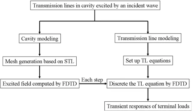
The detailed implementation procedure of this hybrid method is shown in Fig. 1. In the case of transmission lines within a cavity, when the distances of the lines to the reference surface (the bottom surface of cavity) are electrically small compared with the wavelength, the radiation of the transmission lines can be neglected [17]. The excitation fields of transmission lines are the electric fields at the location of the lines in the absence of the lines. Therefore, the geometric model of a shielded cavity without transmission lines is created by CAD software first, and saved as STL format. The auto mesh generator is utilized to read the STL file and reconstruction model for FDTD simulation. Then the FDTD method is used to compute the excitation fields of the transmission lines. The model of transmission lines set up by the TL equations will be transformed into discrete form to adapt to the FDTD. The electric fields obtained by FDTD method will be imported into the TL equations after at every time step. The current and voltage responses of terminal loads will be obtained by iterative solution of the TL equations.
Figure 1. Implementation procedure of the hybrid FDTD-TL method.
2.2. Transmission Line Equations
The coupling model of unshielded transmission lines excited by electromagnetic wave can be described by the transmission line equations as
∂
∂zV (z, t) +RI(z, t) +L ∂
∂tI(z, t) = VF(z, t) (1)
∂
∂zI(z, t) +GV (z, t) +C ∂
∂tV (z, t) = IF(z, t) (2)
of transmission lines, respectively. VF(z, t) and IF(z, t) are distributed voltage and current sources vectors, due to the incident field [13].
[VF(z, t)]i and [IF(z, t)]i can be expressed as
[VF(z, t)]i = − ∂
∂z[ET(z, t)]i+ [EL(z, t)]i (3) [IF(z, t)]i = −C
∂
∂t[ET (z, t)]i (4)
where i stands for the i-th transmission line. [ET(z, t)]i is the integral of the components of incident electric fields that are in the transverse plane and vertical to the i-th transmission line. [EL(z, t)]i is the difference in the longitudinal components of incident electric fields along the position of the i-th transmission line and along the position of the reference conductor. [ET(z, t)]i and [EL(z, t)]i can be expressed as
[ET(z, t)]i = hi
0
eexx (x, yi, z, t)dx (5)
[EL(z, t)]i = eexz (hi, yi, z, t)−eexz (0, yi, z, t) (6)
where eexx and eexz can be computed by the FDTD method. hi denotes the distance between the i-th transmission line and the bottom of the cavity.
The values of [ET(z, t)]i and [EL(z, t)]i at discrete timet=nΔt(n= 0,1,2, . . .) can be written as
[ET (z, nΔt)]i = −Δx·
m=hi/Δx−1
m=0
[eexx (m, yi, z, nΔt)] (7)
[EL(z, nΔt)]i = [eexz (hi, yi, z, nΔt)−eexz (0, yi, z, nΔt)] (8)
where Δx and Δt stand for the spatial step and time step of FDTD, respectively.
The coupling model of shielded transmission line should be considered as a double transmission line systems. The shield of the transmission line and the bottom of the cavity are regarded as the external part. The shielded transmission line is regarded as the inner part. The two parts are connected together with the transfer impedance and admittance of the shield [7]. The external part can be described by the TL Equations (1) and (2). The inner part can be described by the TL equations as
∂
∂zVin(z, t) +RinIin(z, t) +Lin ∂
∂tIin(z, t) = VS(z, t) (9)
∂
∂zIin(z, t) +GinVin(z, t) +Cin ∂
∂tVin(z, t) = IS(z, t) (10) whereVin(z, t) andIin(z, t) represent the voltage and current vector of the transmission line, respectively. Lin,Rin,Cin and Gin denote the per-unit-length inductance, resistance, capacitance, and conductance matrices of the inner transmission lines, respectively. VS(z, t) and IS(z, t) are the distributed voltage and current sources vector, respectively, which are related with transfer parameters, and voltage and current responses on external shield. In the frequency domain, VS(z, ω) andIS(z, ω) can be described as
VS(z, ω) = Zt(ω)I(z, ω) (11)
IS(z, ω) = −Yt(ω)V (z, ω) (12)
where Zt(ω) and Yt(ω) represent the transfer impedance and admittance of shield, respectively. They can be expressed as
Zt(ω) = Rdc+jωLt (13)
Yt(ω) = jωCt (14)
can be described as
VS(z, t) = RdcI(z, t) +Lt∂
∂tI(z, t) (15)
IS(z, t) = −Ct∂t∂V (z, t) (16)
2.3. The Synchronous Computation Formula of Field and Circuit
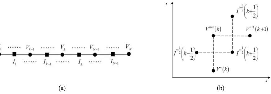
The TL equations are discretized by using the FDTD method. The transmission lines are divided intoN sections. The current and voltage nodes are placed in space and time alternately, as shown in Fig. 2(a). The spatial increment between the adjacent nodes is Δz, and the time step is Δt. The current and voltage nodes are half a space step apart in space and half a time step apart in time, as shown in Fig. 2(b).
(a) (b)
Figure 2. Difference scheme of voltage and current: (a) discretization of a line and (b) interlacing of current and voltage nodes in space and time.
The central difference scheme can be expressed as
∂V (z, t)
∂z =
Vn(k+ 1)−Vn(k)
Δz (17)
∂V (z, t)
∂t =
Vn+1(k)−Vn(k)
Δt (18)
Equations (17) and (18) represent the central differences in space and time. Equations (1), (2), (9), and (10) are discretized by using the scheme of Equations (17) and (18). Finally, the iteration equations can be written as
In+12
k+1 2 = R 2 + L Δt −1 L Δt−
R 2
In−12
k+1 2
− Vn(k+ 1)−Vn(k)
Δz
−ETn(k+ 1)−ETn(k)
Δz +
ELn(k+ 1) +ELn(k) 2
(19)
Vn+1(k) = G 2 + C Δt −1 C Δt −
G 2
Vn(k)−I n+12
k+12 −In+12 k−12 Δz
−CE n+1
T (k)−EnT(k) Δt
In+12 in
k+1 2
=
Lin Δt +
Rin 2
−1
Lin Δt −
Rin 2
In−21 in
k+1 2
−Vinn(k+ 1)−Vinn(k) Δz + Rdc 2 + Lt Δt
In+12
k+1 2 + Rdc 2 − Lt Δt
In−12
k+ 1
2 (21)
Vinn+1(k) =
Cin Δt +
Gin 2
−1
Cin Δt −
Gin 2
Vinn(k)− Ct Δt
Vn+1(k)−Vn(k) (22)
Equations (19) and (20) represent the current and voltage iteration equations of the unshielded transmission lines or the outer system of shielded transmission line, respectively. Equations (21) and (22) represent the current and voltage iteration formulas of the inner system of shielded transmission line, respectively.
3. NUMERICAL EXAMPLES
3.1. Verification of the Hybrid Method
Two numerical examples from references are used to demonstrate the correctness of this hybrid method [17].
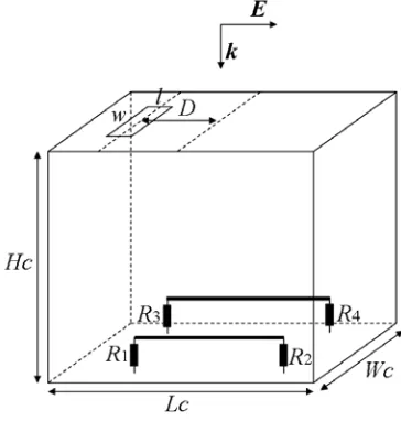
The first case is the simulation of loads’ responses, when two transmission lines in a shielded cavity excited by an incident wave, as show in Fig. 3. The cavity is with lengthLc= 60 cm, widthWc = 20 cm, heightHc = 50 cm, and thicknesstc = 5 mm. There is a slot with lengthl= 2 cm and widthw= 10 cm on the top surface of the cavity. The distance between the center of the slot and the center of the top surface isD= 20 cm. The two transmission lines are both with heighth= 10 mm and radiusr= 1 mm. The distance between the two lines is d= 10 mm. The loadsR1,R2,R3 and R4 of the lines are 50 Ω, 100 Ω, 100 Ω, and 150 Ω, respectively. The waveform of incident electromagnetic field is an exponential pulse, which can be described asE0(t) = exp(−t/t1)−exp(−t/t2), where t1 = 0.5 ns and t2 = 0.2 ns.
As shown in Fig. 4, the black lines and the dash lines are the results from reference [17], the red lines are the results computed by the hybrid FDTD-TL method. We can see from Fig. 4 that the results of these three methods agree well.
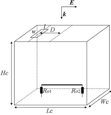
The second example is the simulation of loads’ responses, when the coaxial line in a shielded cavity excited by an incident wave, as show in Fig. 5. The incident wave and the structure of cavity are the same as the first case. The coaxial line is with length 0.5 m and height 10 mm over the bottom of the cavity. The characteristic impedance of the cable is 50 Ω and the relative permittivity of the inner filling material is 1.85. The outer radius of the coaxial cable is 1.52 mm, and the inner radius is 1.40 mm.
(a) (b)
Figure 4. Transient terminal voltages for the first example: (a) Transient terminal voltage of R1 and (b) transient terminal voltage of R4.
Figure 5. Coaxial line in a shielded cavity excited by an incident wave.
The transfer resistance, induce and capacitance of the line are 14.2 mΩ /m, 1.0 nH/m, and 0.091 pF/m, respectively. The outer terminal loadRo1= 100 Ω andRo2 = 150 Ω, and the loadsRi1 andRi2 between the inner wire and the shield are both 50 Ω.
It can be seen from Fig. 6 that the results from reference [17] (the black solid lines and dash lines) and the results computed by the hybrid FDTD-TL method (the red lines) are in good agreements.
In this section, the results computed by our method are compared with the ones obtained by other method from reference [17], the good agreements show the correctness of out method.
3.2. Efficiency of the Hybrid Method
The high efficiency of our method will be demonstrated by the simulation of loads’ responses, when multi-conductor transmission lines in a shielded cavity excited by an incident wave, as shown in Fig. 7. The calculation is done on the DAWN server with 16 cores and memory of 32 GB.
(a) (b)
Figure 6. Transient voltages of the inner terminal loads: (a) voltage of the loadRi1 and (b) voltage of the loadRi2.
Figure 7. Multi-conductor lines in a shielded cavity excited by an incident wave.
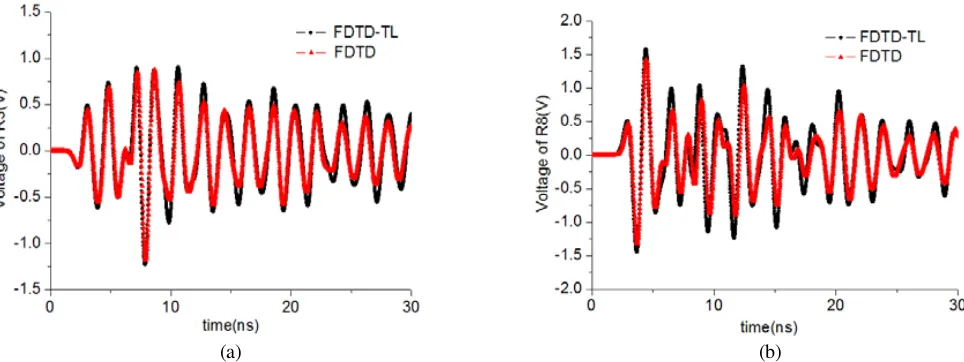
and width ws = 16 mm. The distance between the adjacent slots is D= 20 cm. The multi-conductor transmission lines are all with length l= 32 cm, height h = 20 mm and radiusr = 2 mm. The distance between the adjacent lines is d = 20 mm. In order to compare our results with those computed by traditional numerical method, all loads are selecting pure resistances. The loadsR1,R2,R3,R4 andR5 are all equal to 50 Ω, and the loads R6,R7,R8,R9 and R10 are all equal to 100 Ω. The incident wave is a Gaussian pulse, which can be described by the expression E0(t) = exp(−4π(t−t0)2/τ2), where t0= 1.6 ns and τ = 2 ns.
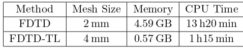
As shown in Fig. 8, the results of our method agree well with those obtained by the FDTD method. Table 1 shows the mesh scale and the time cost in this case by the two methods. As our method can
Table 1. CPU time required by our method and FDTD method.
Method Mesh Size Memory CPU Time
FDTD 2 mm 4.59 GB 13 h20 min
(a) (b)
Figure 8. Transient voltages of terminal loads: (a) voltage of the load R3 and (b) voltage of the load R8.
use larger mesh size than the FDTD method, which leads the memory requirement of our method is much less, the computation via our method requires less CPU time.
4. CONCLUSIONS
In this paper, we propose a hybrid FDTD and transmission line equations method for computing the transient responses of transmission lines in cavity excited by an incident wave. It is synchronous for the fields and circuits computation in our method. The FDTD method combined with STL mesh generator is employed to compute the excited electromagnetic fields of transmission lines efficiently, and the TL equations are utilized to compute the responses of terminal loads. The results obtained by our method agree well with those obtained by other methods, which verifies the correctness of our method. The simulation time with our method is much less than the time cost by the FDTD method in testing, which shows the high efficiency of our method.
ACKNOWLEDGMENT
This work was supported by the National Basic Research Program of China (973 Program, Grant No. 2013CB328904) and the State Key Program of National Natural Science Foundation of China (Grant No. 61231003).
REFERENCES
1. Phumin, K., S. J. Yakura, C. Christos, and E. I. Naz, “An electromagnetic topology method for cable interactions using a radiating dipole at apertures,”IEEE Antennas and Wireless Propagation Letters, Vol. 5, 220–223, 2006.
2. Phumin, K., R. W. Justin, S. J. Yakura, C. Christos, and E. I. Naz, “A modular junction topological approach to aperture — System interaction problem,” IEEE Antennas and Wireless Propagation Letters, Vol. 6, 296–299, 2007.
3. Jin, T., Q. Yang, and L. Ankun, “Generalized analysis model of information security of computer system based on electromagnetic topology,” Fifth International Conference on Information Assurance and Security, 766–769, 2009.
5. Wang, J. G., G. Z. Liu, and J. S. Zhou, “Investigations on function for linear coupling of microwaves into slots,”High Power Laser and Particle Beams, Vol. 15, No. 11, 1093–1099, 2003.
6. Bopp III, C. L. and C. M. Butler, “Analysis of transmission of a signal through a complex cylindrical/coaxial cavity by transmission line methods,” Progress In Electromagnetics Research, Vol. 56, 33–51, 2006.
7. Jayasree, P. V. Y., V. S. S. N. S. Baba, B. Prabhakar Rao, and P. Lakshman, “Analysis of shielding effectiveness of single, double and laminated shields for oblique incidence of EM waves,” Progress In Electromagnetics Research B, Vol. 22, 187–202, 2010.
8. Xie, L. and Y. Z. Lei, “Transient response of a multiconductor transmission line with nonlinear terminations excited by an electric dipole,” IEEE Transactions on Electromagnetic Compatibility, Vol. 51, No. 3, 805–810, 2009.
9. Yu, Q., Y. D. Wang, J. H. Han, C. X. Zhang, and M. Liu, “Development of the BLT equation in the time domain and its application in line,”Systems Engineering and Electronics, Vol. 33, No. 11, 2372–2376, 2011.
10. Li, X. D., Q. G. Wang, X. Zhou, and S. L. Qin, “The research of electromagnetic conducted coupling in transmission-line,”International Conference on Electronics and Optoelectronics, 110–112, 2011. 11. Kong, Y.-D., Q.-X. Chu, and R.-L. Li, “High-order unconditionally-stable four-step ADI-FDTD methods and numerical analysis,”Progress In Electromagnetics Research, Vol. 135, 713–734, 2013. 12. Xiong, R., B. Chen, J.-J. Han, Y.-Y. Qiu, W. Yang, and Q. Ning, “Transient resistance analysis of large grounding systems using the FDTD method,”Progress In Electromagnetics Research, Vol. 132, 159–175, 2012.
13. Xiong, R., B. Chen, Y. Mao, B. Li, and Q.-F. Jing, “A simple local approximation FDTD model of short apertures with a finite thickness,”Progress In Electromagnetics Research, Vol. 131, 135–152, 2012.
14. Chen, J. and J. G. Wang, “A three-dimensional semi-implicit FDTD scheme for calculation of shielding effectiveness of enclosure with thin slots,” IEEE Transactions on Electromagnetic Compatibility, Vol. 49, No. 2, 354–360, 2007.
15. Chen, J. and J. G. Wang, “A three-dimensional HIE-PSTD scheme for simulation of thin slots,” IEEE Transactions on Electromagnetic Compatibility, Vol. 55, No. 6, 1239–1249, 2013.
16. Xie, H., J. Wang, R. Fan, and Y. Liu, “Study of loss effect of transmission lines and validity of a SPICE model in electromagnetic topology,” Progress In Electromagnetics Research, Vol. 90, 89–103, 2009.
17. Xie, H. Y., J. G. Wang, R. Y. Fan, and Y. N. Liu, “A hybrid FDTD-SPICE method for transmission lines excited by a nonuniform incident wave,”IEEE Transactions on Electromagnetic Compatibility, Vol. 51, No. 3, 811–817, 2009.