A Compact Wideband Slot Antenna for Universal UHF RFID
Reader
Marwa Zamali1, Lotfi Osman1, *, Hedi Raggad1, and Mohamed Latrach2
Abstract—In this letter, a new wideband circularly polarized antenna for Radio Frequency Identification (RFID) readers is proposed. A prototype operating in the Ultra-High Frequency (UHF) band is successfully realized and tested using a defected Ground Structure (DGS). This antenna consists of an L-shaped metal strip and a DGS with four tuning stubs. The overall size covers 90∗90∗1.6 mm3. The measured−10 dB reflection coefficientS11bandwidth is 27% (800–1020 MHz), and a good radiation pattern and suitable gain coefficient about 3.7 dB have been achieved. Also, an excellent agreement was noticed between simulation and measurement results demonstrating the good performance of the proposed antenna.
1. INTRODUCTION
RFID continues to be a key issue in several applications, such as supply chain management, smart pursuit and supply [1]. In fact, RFID is growing quickly in several technologies. It generally includes a tag and a reader. One of the most necessary parts of an RFID system is certainly the reader antenna whose polarization should be circular in the UHF band. This type of polarization reduces certain losses when receiving signals [2]. Circular polarization can be obtained by the combination of two orthogonal linearly polarized modes with a 90◦ as phase offset and same amplitude [3, 4]. Moreover, it facilities the detection of the arbitrarily oriented tag in many operational conditions. The UHF RFID system is still working in many bands for various regions like China (840.5–844.5 MHz), India (865–867 MHz), Singapore (866–869 MHz, 923–928 MHz), and Europe (865–867 MHz) [5]. The main disadvantage of these bands is the requirement of a big antenna, which has prompted researchers to find a solution to reduce its dimensions while keeping its own characteristics in terms of gain, bandwidth, radiation patterns, polarization and gain. Different miniaturization techniques are suggested to cut back overall dimensions or to achieve a resonance frequency at physical dimensions much less than the half-free area wavelength (λ0 = C0/f0). That is why there exist various techniques which have been proposed by antenna designers, such as using inductive and capacitive loading, metamaterials, slots on a patch [6], fractals [7], shorting pins and plates [8] as well as high dielectric constant substrates [9]. The Defected Ground Structure (DGS) technology has also been used to miniaturize the reader antenna while improving the characteristics of the antennas [10, 11]. Recently, DGS has been speedily developed within the UHF RFID system. It consists in etching a certain geometrical shape in the antenna ground plane [12]. It can be dependent on the performance desired to make the surface current distribution in the ground plane, control the propagation of the electromagnetic waves through the substrate layer and produce the slow wave effect [13, 14]. Indeed, several DGS shapes such as partial ring [15], spiral [16], annual ring [17], and spiral have been proposed to enhance characteristics of the antenna, especially to
Received 3 April 2018, Accepted 23 July 2018, Scheduled 28 August 2018
* Corresponding author: Marwa Zamali (zamali.marwa@hotmail.com).
improve the radiation efficiency and remove harmonics. In other words, they can decrease the resonance frequency leading to the reduction of the antenna size for the desired frequency.
The comparison of CP microstrip antenna in this letter with other CP antennas reported in the literature is shown in Table 1. We can notice that the proposed antenna has a wider S11 bandwidth and a compact size than another reader antenna. The comparison results indicate that the proposed antenna uses a different approach to realize the CP operation, which is easy to fabricate and to integrate into different applications due to its small volume.
Table 1. Comparison of different CP antennas.
Antenna References
S11<−10 dB (MHz)
AR<3 dB (MHz)
Gain (dBi)
Dimensions (mm3) Reference [18] 760–1050 890–940 9.7 355∗405∗30 Reference [19] 840–960 837–963 7.17 250∗250∗36 Reference [20] 890–1016 890–950 - 90∗65∗0.8
Proposed (800–1020) (849–879) 3.7 90∗90∗1.6
Our contribution is to fabricate a circular polarization (CP) antenna with DGS decreasing the resonance frequency by 77% and increasing the gain by 63% while keeping the circular polarization. Simulations under CST were performed, and experimental tests were conducted to validate the results obtained.
2. ANTENNA CONFIGURATION
2.1. Design of the Patch Antenna with DGS
The design of the proposed antenna is depicted in Figure 1. This antenna consists of an FR4 substrate with εr = 4.4, tgδ = 0.02 and thickness h = 1.6 mm. It can be seen that the metal layer is an L-shaped piece with a rectangular slot printed on the upper surface of the substrate. The L shape is used to generate two resonant modes, and the combination of two resonant modes can realize wideband frequency, whereas the circular-shaped ground plane is loaded by four stubs in the diagonal directions to generate the circular polarization.
(b)
(a) (c)
Figure 1. Design of the proposed antenna. (a) Front view. (b) Back view. (c) Perspective view.
Table 2. Dimensions of the proposed antenna (unit: mm).
a b C d m n o p q r
90 8.8 10 35 20 3 16.6 8 10 21
Figure 2. SimulatedS11 with and without DGS.
2.2. Parametric Studies
To understand the performance of some parameters of the antenna, we have examined the effects of the variations of both the length and width of the stub on the resonance frequency and axial ratio.
Indeed, Figure 3 provides the influence of the stub lengths on the reflection coefficient. As a result, there will be no reflection if the stubs are removed.
Figure 3. Reflection coefficient with varied L.
Figure 4. Axial ratio according to the width of the stub (b).
3. SIMULATION AND MEASUREMENT RESULTS
The fabrication of the prototype is shown in Figure 5.
The prototype is measured in an anechoic chamber using an Agilent Vector Network Analyzer. This antenna is fed by 50 Ω microstrip line using the SMA connector.
(b) (a)
Figure 5. Photographs of the realized antenna: (a) Front view. (b) Back view.
From Figure 6, the measured bandwidth forS11 greater than −10 dB is around 27% (0.800 GHz– 1.05 GHz) thus covering the Ultra-High Frequency RFID band. The bandwidth is calculated as follows
BW% = 2(fmax−fmin) fmax+fmin ×
100 (1)
The curves of the axial ratio (AR) are presented in Figure 7. It is found that the measured 3 dB AR bandwidth is 12% (0.849–0.879 GHz) and that a good CP radiation is achieved.
The proposed antenna is established to be the dimension of 90×90 mm2 as to create TE01 and TE10 components of CP. Theoretically, the operating frequency can be calculated by Equation (2).
fc = 2π√cε
eff ×
mπ
a1
2 +
nπ b2
2
In Eq. (2), c is 3×10⁸m/s; εeff is the effective permittivity of the FR4 substrate; a1 is the resonant length of the ground plane of the antenna in mode TE10 (a1 = 90 mm);b1 is the resonant length of the patch of the antenna in the mode TE01 (b1= 62 mm).
The L-shaped strip is etched on the front side of the FR4 substrate. The vertical and horizontal portions of the L-shaped strip are parallel toY axis andX axis, respectively, which generates 90 degrees shift phase between Ex and Ey.
Note that from Figure 8, the simulated impedance and resultant phase of the TE01mode operating at 0.852 GHz can be determined as follows
Zin = Rin+jXin= 52.79 +j20.76 (Ω) (3)
Γ = Zin−ZO Zin+Z0
= 52.79−j20.76−50 52.79 +j20.76 + 50 =
2,79 +j20.75
102.79 +j20.75 = 019 + 80.04
◦ (4)
For TE10 mode, it is operated at 0.952 GHz. The input impedance and phase angle are
Zin = Rin+jXin= 11.47 +j3.06 (5)
Γ = Zin−ZO Zin+Z0
= 11,47−j3,06−50 11,47 +j3,06 + 50 =
38.53 +j3.06
61,47 +j3,06 = 0.64 + 173
◦ (6)
The difference between the two orthogonal modes is about 92◦. So, there is a phase shift between TE01 and TE10 of almost π/2. This proves that the proposed antenna fulfils all requirements for the generation of the CP radiation.
Figure 6. Results ofS11 parameter. Figure 7. Results of axial ratio.
Figure 9 shows the simulated and measured peaks of the realized gain at several distinct frequencies. The obtained results are in sensible agreement, particularly at 0.866 GHz where the gain is close to 3.7 dB.
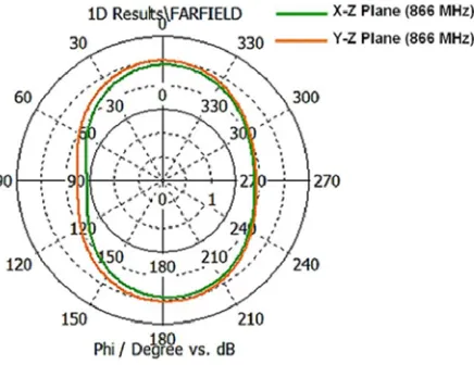
The radiation patterns at 0.866 GHz in X-Z and Y-Z planes are displayed in Figure 10. As expected, a quasi-omnidirectional radiation performance is obtained.
The realized antenna has a small size and good performance, which allows us to integrate it into handheld devices in the RFID reader system for use in the health sector.
Indeed the use of UHF RFID in the health sector ensures asset tracking, identity management and access, and tracking the location of patients.
Figure 8. The reflection phase of the proposed antenna.
Figure 9. Simulation and measurement of the peaks of the realized gain.
Figure 10. Radiation patterns at 0.866 GHz of the proposed antenna.
4. CONCLUSION
A new broadband CP reader antenna structure operating at 0.866 GHz is proposed and studied in this letter. The bandwidth of the antenna is around 220 MHz with a measured AR of almost 12% and a gain approximately equal to 3.7 dB. This antenna is characterized by a compact size, good radiation performance and relatively high gain. An excellent consistency between simulation and measurement results is observed. Our study could also be exploited in other interesting applications such as treatment and monitoring in mobile medicine, transmission security and access control.
REFERENCES
1. Wang, Z., S. Fang, S. Fu, and S. Jia, “Single-fed broadband circularly polarized stacked patch antenna with horizontally meandered strip for universal UHF RFID applications,” IEEE Transactions on Microwave Theory and Techniques, Vol. 59, No. 4, 1066–1073, 2011.
3. Lee, D. H., P. J. Park, J. P. Kimand, and J. H. Choi, “Aperture-coupled UHF reader antenna for a handheld application,” Micro. Opt. Technol. Lett., Vol. 50, 1261–1263, May 2008.
4. Chang, T. N. and J. M. Lin, “A novel circularly polarized patch antenna with serial multislot type loading,” IEEE Trans. Antennas Propag., Vol. 55, 3345–3348, Nov. 2007.
5. Tang, Z. J. and Y. G. He, ‘Broadband microstrip antenna with U and T slots for 2.45/2.41 GHz RFID tag,”Electronic Letters, Vol. 45, No. 18, 926–928, 2009, doi: 10.1049/el.2009.0387.
6. Nasimuddin, Z. N. Chen, and X. Qing, “Slotted microstrip antennas for circular polarization with compact size,” IEEE Antennas Propag. Mag., Vol. 55, No. 2, 124–137, 2013.
7. Oraizi, H. and S. Hedayati, “Miniaturized UWB monopole microstrip antenna design by the combination of Giuseppe Peano and Sierpinski Carpet fractals,” Antennas Wirel. Propag. Lett., Vol. 10, 67–70, 2011.
8. Lamminen, A. E. I., A. R. Vimpari, and J. Saily, “UC-EBG on LTCC for 60-GHz frequency band antenna applications,” IEEE Trans. Antennas Propag., Vol. 57, No. 10, 2904–2912, 2009.
9. Wong, K. L.,Compact and Broadband Microstrip Antennas, 1st Edition, Wiley, NJ, 2002.
10. Kumar, C. and D. Guha, “Linearly polarized elliptical microstrip antenna with improved polarization purity and bandwidth characteristics,” Microw. Opt. Technol. Lett., Vol. 54, No. 10, 2309–2314, 2012.
11. Prajapati, P. R., G. G. K. Murthy, A. Patnaik, and M. V. Kartikeyan, “Design of compact circular disc circularly polarized antenna with Koch curve fractal defected ground structure,”Proc. of 31st Int. Union of Radio Science General Assembly and Scientific Symp., (URSI GASS 2014), Beijing, China, August 2014.
12. Zhang, C., J. Zhang, and L. Li, “Triple band-notched UWB antenna based on SIR-DGS and fork-shaped stubs,”Electronics Letters, Vol. 50, No. 2, 67–69, 2014.
13. Chi, P.-L. and T. Itoh, “Antenna miniaturization using slow wave enhancement factor from loaded transmission line models,”IEEE Trans. Antennas Propag., Vol. 59, No. 1, 48–57, 2011.
14. Kim, H.-M. and B. Lee, “Bandgap and slow/fast wave characteristics of defected ground structures including lefthanded features,” IEEE Trans. Microw. Theory Tech., Vol. 54, No. 7, 3113–3120, 2006.
15. Biswas, S., D. Guha, and C. Kular, “Control of higher harmonics and their radiation in microstrip antennas using compact defected ground structures,” IEEE Trans. Antennas Propag., Vol. 61, No. 6, 3349–3354, 2013.
16. Nashaat, D., H. A. Elsadek, E. Abdallah, H. Elhenawy, and M. F. Iskander, “Multiband and miniaturized inset feed microstrip patch antenna using multiple spiral-shaped defected ground structure (DGS),” Proc. Of IEEE Antennas and Propagation Society Int. Symp., (APSURSI’09), 164, Charleston, South Carolina, 2009.
17. Guha, D., S. Biswas, and C. Kumar, “Annular ring shaped DGS to reduce mutual coupling between two microstrip patches,” Proc. of IEEE Applied Electromagnetics Conf. (AEMC), 1–3, Kolkata, India, 2009.
18. Cheng, K. S., E.-H. Lim, and Y.-N. Phua, “Circularly polarized suspended patch antenna fed by modified L-Probe for UHF RFID Reader,”Radio Engineering, Vol. 26, No. 4, December 2017. 19. Pan, Y., L. Zheng, H. J. Liu, J. Y. Wang, and R. L. Li, “Directly-fed single-layer wideband RFID
reader antenna,” Electronic Letters, Vol. 48, No. 11, May 24, 2012.