Multiwall Carbon Nanotube Impedance Matching Section
Tayfun G¨unel*
Abstract—In this work, computer-aided impedance analysis and genetic-based synthesis of a multiwall carbon nanotube impedance matching section (MWCNTIMS) are proposed. Transmission line model (TLM) of a multiwall carbon nanotube is used for the computer-aided impedance analysis. Continuous parameter genetic algorithm (CPGA) is used for the genetic-based synthesis. A simple, fast, and effective impedance analysis and synthesis approach for an MWCNTIMS is presented. The results of the analysis and synthesis for different examples of MWCNTIMS are given and discussed in detail. The results show that the effect of variation of the distance from the ground plane of the outer shell is very small on the values of input resistance and input reactance. The values of input resistance and input reactance decrease while the value of inner radius or the total number of shells increases. Since the diameter increases with the increasing value of inner radius and the total number of shells, the values of input resistance and input reactance decrease with increasing diameter. While the value of nanotube length increases, the values of input resistance and input reactance increase.
1. INTRODUCTION
In recent years, a lot of research has been performed on carbon nanotubes (CNTs), their applications, transmission line models of a single wall carbon nanotube (SWCNT) and a multiwall carbon nanotube (MWCNT) [1–12]. CNTs are formed by graphene layers wrapped to cylinders. If they are wrapped as a single layer, it is called SWCNT. If they are wrapped as a multilayer it is called MWCNT. Computer-aided noise analysis of an MWCNT is recently presented in [13]. A simple, fast, and effective impedance analysis and synthesis approach to an MWCNTIMS is proposed in this work. Impedance matching is important for three main reasons [14]. The first reason is that the maximum power is delivered, and power loss in the feed line is minimized. The second reason is the improvement of signal-to-noise ratio of the system by impedance matching receiver components. The third reason is the reduction of amplitude and phase errors by impedance matching in a power distribution network. As far as the author knows, theoretical work does not exist in the literature for the analysis and synthesis of an MWCNTIMS by using the TLM of an MWCNT. In this work, TLM of an MWCNT given in [12] is used for the analysis, and TLM of an MWCNT and CPGA are used for the synthesis. Genetic algorithm (GA) is a global optimization algorithm based on evolution and genetic recombination in nature [15, 16]. In a CPGA, the parameters constituting a chromosome are coded by a single floating-point number. GA and its versions have been extensively used in microwave theory and electromagnetics [17–22]. The other sections of this work are as follows: After the theory is given in Section 2, simulation results are presented and discussed in Section 3. In Section 4, the paper is concluded.
Received 23 September 2019, Accepted 11 January 2020, Scheduled 21 January 2020
* Corresponding author: Tayfun G¨unel ([email protected]).
2. THEORY
The equation for the computation of input impedance of a uniform lossy transmission line terminated in a load impedance (ZL=RL+jXL) at a frequency (f) can be given as in [14]
Zin =Rin+jXin =ZoZL
+ZotanhγL
Zo+ZLtanhγL
(1)
whereRin is the input resistance, Xin the input reactance, γ the propagation constant,L the length of
the line from the load impedance, and Zo the characteristic impedance of the line. The characteristic
impedance of the line is calculated by
Zo=
Z
Y (2)
where Z and Y are the per-unit length impedance and per-unit length admittance, respectively. γ is computed from
γ =√ZY (3)
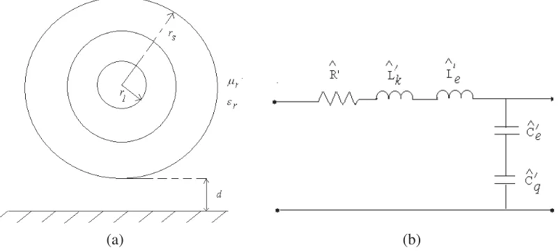
Figure 1(a) shows the cross section of an MWCNT withsshells above the ground plane. Equivalent single conductor model (ESCM) of an MWCNT is represented in Figure 1(b).
(a) (b)
Figure 1. (a) Schematic representation of a MWCNT cross section. (b) Circuit representation of the ESCM of a MWCNT.
Z andY are computed by
Z = R+jωL (4)
Y = jωC (5)
L and C are given by
L = Lk+Le (6)
C = C
eCq
Ce +Cq (7)
The error function for the synthesis of an MWCNTIMS is formed as follows
E =Rcin−Rdin+Xinc −Xind (8)
where Rcin, Rdin, Xinc , and Xind are the computed input resistance, desired input resistance, computed input reactance, and desired input reactance of an MWCNTIMS at a given frequency respectively. The distance from the ground plane of the outer shell (d), the inner radius (r1), the total number of shells (s), and the nanotube length (L) are selected as unknown values for the synthesis of an MWCNTIMS.
3. SIMULATION RESULTS
Input impedance values of an MWCNTIMS in a frequency range between 0.1 GHz and 100 GHz are calculated by using Eq. (1) for different values of d, r1, s, and L. The values of intershell distance, per-unit-length damping resistance, and load impedance are chosen as 0.34 nm, 25.8 kΩ/µm, and 50 Ω, respectively. It is supposed that the MWCNTIMS is embedded in air.
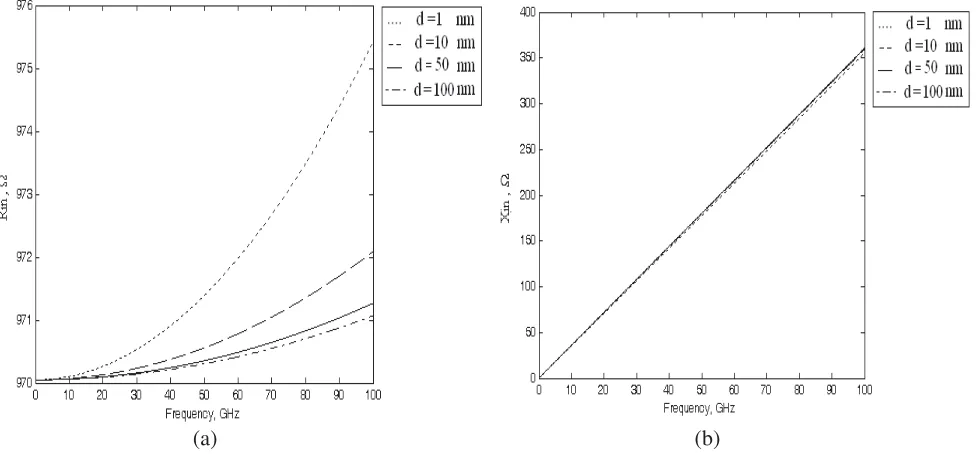
Figure 2 shows the frequency variation of Rin and Xin of the MWCNTIMS for different values of
d if the values of r1, s, L, and ZL are kept constant (r1 = 0.5 nm, s = 10, L = 0.5µm, ZL = 50 Ω).
Change in the values of Rin and Xin is very small with increasing values ofdfor a fixed value of ZL if
the other parameters are kept constant.
(a) (b)
Figure 2. (a) Input resistance. (b) Input reactance of the MWCNTIMS for different values ofd.
If the values ofd,s,L, andZL are kept constant (d= 1 nm,s= 10, L= 0.5µm, ZL = 50 Ω), the
frequency variation of Rin and Xin of the MWCNTIMS for different values of r1 is given in Figure 3. The value of Rin decreases from 980 Ω to 140 Ω, and the maximum value of Xin at 100 GHz decreases
from 355 Ω to 40 Ω with increasing values of r1 if the other parameters are kept constant.
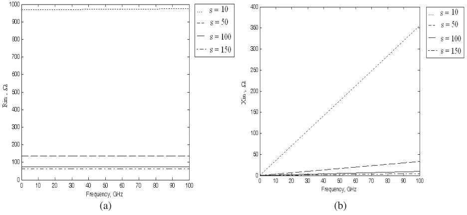
Figure 4 shows the frequency variation of Rin and Xin of the MWCNTIMS for different values of
s ifd, r1, L, andZL are kept constant (d= 1 nm, r1 = 0.5 nm, L = 0.5µm, ZL = 50 Ω). The value of
Rin decreases from 980 Ω to 70 Ω, and the maximum value of Xin at 100 GHz decreases from 355 Ω to
10 Ω with increasing values ofs if the other parameters are kept constant.
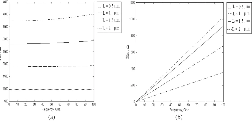
If the values of d,r1,s, andZL are kept constant (d= 1 nm,r1= 0.5 nm,s= 10, ZL= 50 Ω), the
frequency variation of Rin and Xin of the MWCNTIMS for different values of L is given in Figure 5.
(a) (b)
Figure 3. (a) Input resistance. (b) Input reactance of the MWCNTIMS for different values ofr1.
(a) (b)
Figure 4. (a) Input resistance. (b) Input reactance of the MWCNTIMS for different values ofs.
at 100 GHz increases from 360 Ω to 1020 Ω with increasing values ofL if the other parameters are kept constant.
(a) (b)
Figure 5. (a) Input resistance. (b) Input reactance of the MWCNTIMS for different values ofL.
Figure 6. Error function value versus iteration number.
Table 1. The results of the examples for the synthesis of MWCNTIMS.
Example 1 Example 2 Example 3
d(nm) 1.29 2.39 1.39
r1 (nm) 89.87 95.51 82.61
s 99 97 98
L(µm) 25.71 17.36 19.45
f (GHz) 50 75 100
ZL=RL+jXL(Ω) 100 100 +j50 100 +j50
Zind =Rdin+jXind (Ω) 300−j100 300 300 +j100 Zinc =Rcin+jXinc (Ω) 299.99−j99.91 299.96−j0.005 300 +j99.92
4. CONCLUSION
Computer-aided impedance analysis and genetic-based synthesis of an MWCNTIMS are presented. TLM of an MWCNT is used for the impedance analysis, and TLM and CPGA are used for the synthesis. The results of the analysis and synthesis for different examples of MWCNTIMS are given and discussed in detail. The results show that the effect of variation of the distance from the ground plane of the outer shell on the value of input resistance and reactance is very small. The values of input resistance and input reactance decrease while the value of inner radius or the total number of shells increases. Since the diameter increases with the increasing value of inner radius and the total number of shells, the values of input resistance and input reactance decrease with increasing diameter. While the value of nanotube length increases, the values of input resistance and input reactance increase. The simple, fast, and effective approach presented in this work can be used for impedance analysis and synthesis of different types of impedance matching sections as well as an MWCNTIMS.
REFERENCES
1. Saito, R., M. Fujita, G. Dresselhaus, and M. S. Dresselhaus, “Electronic structure of chiral graphene tubules,”Appl. Phys. Lett., Vol. 60, No. 18, 2204–2206, 1992.
2. Hoenlein, W., F. Kreupel, G. S. Duesberg, A. P. Graham, M. Liebau, R. V. Seidel, and E. Unger, “Carbon nanotube applications in microelectronics,” IEEE Trans. Compon. Packag. Technol., Vol. 27, No. 4, 629–634, 2004.
3. Song, Y. S. and J. R. Youn, “Influence of dispersion states of carbon nanotubes on physical properties of epoxy nanocomposites,” Carbon, Vol. 43, No. 7, 1378–1385, 2005.
4. Rosa, I. M. D., F. Sarasini, M. S. Sarto, and A. Tamburrano, “EMC impact of advanced carbon fiber /carbon nanotube reinforced composites for next generation aerospace applications,” IEEE Trans. EMC, Vol. 50, No. 3, 556–563, 2008.
5. You, K. and K. Nepal, “Design of a ternary static memory cell using carbon-nanotube -based transistors,”Micro &Nano Letters, Vol. 6, No. 6, 381–385, 2011.
6. Attiya, A. M., “Nanotechnology in RF and microwave applications: Review article,” 29th National
Radio Science Conference (IEEE Catalog Number: CFP12427-PRT), 9–18, Cairo, Egypt, 2012.
7. Bockrath, M. W., “Carbon nanotubes: Electrons in one dimension” Ph.D. dissertation, Univ. California, Berkeley, CA, 1999.
8. Burke, P. J., “Luttinger liquid theory as a model of the gigahertz electrical properties of carbon nanotubes,”IEEE Trans. Nanotech., Vol. 1, No. 3, 129–144, 2002.
9. Burke, P. J., “An RF circuit model for carbon nanotubes,” IEEE Trans. Nanotechnol., Vol. 2, No. 1, 55–58, 2003.
10. Salahuddin, S., M. Lundstrom, and S. Datta, “Transport effects on signal propagation in quantum wires,” IEEE Trans. Electron. Devices, Vol. 52, No. 8, 1734–1742, 2005.
11. Li, H., W. Y. Yin, K. Banerjee, and J. F. Mao, “Circuit modeling and performance analysis of multi-walled carbon nanotube interconnects,” IEEE Trans. Electron. Devices, Vol. 55, No. 6, 1328–1337, 2008.
12. Sarto, M. S. and A. Tamburrano, “Single-conductor transmission-line model of multiwall carbon nanotubes,”IEEE Trans. Nanotech., Vol. 9, No. 1, 82–92, 2010.
13. G¨unel, T., “Computer-aided noise analysis of a multiwall carbon nanotube,”Micro&Nano Letters, Vol. 13, No. 2, 165–170, 2018.
14. Pozar, D. M., Microwave Engineering, John Wiley and Sons, USA, 1998. 15. Holland, J. H., “Genetic algorithms,” Scientific American, 44–50, July 1992.
16. Haupt, R. L. and S. E. Haupt, Practical Genetic Algorithms, 2nd Edition, A John Wiley & Sons, Inc., N.Y., 2014.
18. Johnson, J. M. and Y. Rahmat-Samii, “Genetic algorithms in engineering electromagnetic,” IEEE Antennas Propagation Mag., Vol. 39, No. 4, 7–25, 1997.
19. Weile, D. and E. Michielssen, “Genetic algorithm optimization applied to electromagnetics: A review,”IEEE Trans. Antennas Propagat., Vol. 45, No. 3, 343–353, 1997.
20. G¨unel, T. and E. Aydemir, “Application of continuous parameter genetic algorithm to the problem of synthesizing bandpass distributed amplifiers,”AE ¨U (International Journal of Electron. Commun.), Vol. 56, No. 5, 351–354, 2002.
21. G¨unel, T. and I. Erer, “Application of fuzzy genetic algorithm to the problem of synthesizing circular microstrip antenna elements with thick substrates,” AE ¨U (International Journal of Electron. Commun.), Vol. 56, No. 3, 215–217, 2002.