VICTORIA UNIVERSITY OF TECHNOLOGY
DEPARTMENT OF MECHANICAL ENGINEERING
MODELLING THE SCAVENGING PROCESS
IN A TWO-STROKE I.C. ENGINE
BY
QIXIAN ZHANG
A RESEARCH THESIS SUBMITTED IN FULFILMENT OF
THE REQUIREMENT FOR THE DEGREE OF MASTER OF ENGINEERING
BY RESEARCH
FTS THESIS ~ ~ " ^ —
621.430113 ZHA
ACKNOWLEDGMENT
The w o r k reported in this thesis was carried out in the Department of Mechanical Engineering of the Victoria University of Technology.
I would like to express my deep gratitude and thanks to my supervisor, Dr. Michael Sek, for his valuable guidance and patient support of this work. Without his vision and constructive
suggestion this project would not have been possible. H e has been a great source of encouragement.
I am grateful to thank Professor Geoff Lleonart for his valuable consultation and patient correction of this thesis. Without his critical vision, this thesis would not achieve its current quality.
I wish to thank the head of Mechanical Engineering Department, Associate Professor Kevin Duke, for the part-time employment I w a s offered which enable m e to finish m y study.
I wish to thank the technical staff at the Department of Mechanical Engineering, especially Mr. Harry Friedrich, R a y Mackintosh and Harry Braley, for their practical assistance o n m a n y
occasions.
I am thankful to Yamaha Australia for their kind donation of a Yamaha two-stroke engine to the Department of Mechanical Engineering. All engine testing w a s conducted on this engine.
I am grateful to my friend, Mr. Cliff Hadley, especially for his help and encouragement. He also helped m e to correct this thesis.
I am highly obliged to my beloved wife Xin Yuan, and lovingly daughter Katie, who was born at the conclusion of this project. Without Xin's understanding and moral support, I would not be able to brave enough to complete this work. She also helped m e greatly in binding this thesis before it comes to publication.
ABSTRACT
The primary concern associated with a two-stroke engine performance is its gas exchange process (scavenging process). The success of the scavenging process greatly affects the thermodynamic properties of cylinder content at the trapping conditions and hence the combustion and power output The unsteady gas flow in engine pipes has a marked influence on the scavenging process.
In the current study, the two-stroke engine simulation model has been developed to predict the steady state performance characteristics of a crankcase compressed, piston port-timed,
two-stroke engine equipped with expansion chamber. T h e characteristics include parameters such as engine torque and power, B S F C , scavenging efficiency and charging efficiency. The m o d e l also has the ability to predict the unsteady gas dynamic behaviour in various engine pipes. The instantaneous pressure fluctuation and mass flow rates at inlet port, transfer port and exhaust port were calculated and analysed.
The model has several advantages compared with other one-dimensional isentropic model. It includes an improved procedure to account for the variation in geometry of pipe and to determine the thermodynamic states in cylinder/crankcase. T h e model also considered the temperature discontinuity at port/pipe interface. All these efforts increase the accuracy and numerical stability of the prediction.
A single cylinder two-stroke engine dynamometer rig and dedicated fast data acquisition hardware and software have been developed in the project. Engine torque, speed and fuel consumption can be measured on the dynamometer rig. The dynamic pressure signals in engine cylinder, transfer port and exhaust port, together with crankshaft position signal, can be acquired at a speed of 50,000 sample/second per channel, sufficient for accurate acquisition of experimental data.
NOMENCLATRUE
English: a
*
a
a
0.xA
BDC
BMEP
BSFC
C
c
C+
yC.
Q
Co
c
PCV1 C V 2 E E P C E P O h h H I M E P IPC IPO K
local speed of sound (m/s) non-dimension speed of sound
speed of sound at reference pressure (m/s) reference speed of sound at location x (m/s) area ( m2)
bottom dead center
brake m e a n effective pressure (kpa) brake specific fuel consumption (kg/kw*h) denotes characteristic curves
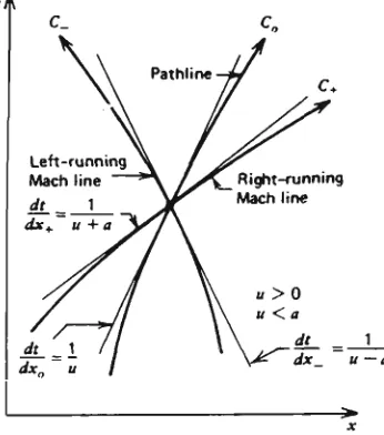
w a v e propagation velocity (m/s) unsteady flow M a c h lines
unsteady flow path line coefficient of contraction coefficient of discharge
specific heat at constant pressure (J/kg*K) specific heat at constant volume (J/kg*K) control volume 1, ie, the cylinder
control volume 2, ie, the crankcase system interanl energy (J/kg) exhaust port closure
exhaust port open
enthalpy (J/kg) effective port height ( c m )
geometric port height ( c m ) indicated m e a n effective pressure (kpa) inlet port closure
instantenous port/pipe area ratio effective port width (cm) differential operator
length of the middle parallel section of the exhaust pipe ( m m ) local M a c h number
mass flow rate (kg/s)
node n at n e w time step in the physical (Z-X) plane pressure (pa)
reference pressure (pa)
pressure difference between crankcase and cylinder (kpa) pressure of the incident w a v e (pa)
pressure of the reflecting w a v e (pa)
heat transfered to or from the system (J/kg) gas constant (J/kg*K)
universal gas constant (J/kg*K) revelotion per minute
transfer port area ratio throttle area ratio
gas temperature (K) time (sec)
reference temperature (gas temperature at reference pressure) top dead center
transfer port closure transfer port open
gas particle velocity (m/s)
gas particle velocity on simple pressure w a v e (m/s) relative velocity (m/s)
gas particle velocity on superposed pressure w a v e (m/s) non-dimensional gas particle velocity
w o r k (J/kg)
x distance (m)
x the scavenging ratio at displacement/mixing transition point in Benson-Brandham scavenging model
X pressure amplitude ratio
X , pressure amplitude ratio in cylinder X4 pressure amplitude ratio of incident w a v e
XL pressure amplitude ratio of left-ward running w a v e XR pressure amplitude ratio of right-ward running w a v e X , pressure amplitude ratio of reflecting w a v e
Xs superposition pressure amplitude ratio
y the proportion of short-circuiting in Benson-Brandham scavneging model
Z non-dimensional time
Greek:
B the group (2Xrl)/X,
y ratio of specific heat
A Z non-dimensional time increment E mass imbalance rate in duct
r\c charging efficiency r\s scavenging efficiency
0M port axial inclination angle
Q^ port tangential inclination angle
\i delivery ratio
\ scavenging ratio
X,p R i e m a n n variable
X, p R i e m a n n variable after considering the effect of non-uniform
reference temperature
A ^ , pn» Riemann variable at node n at n e w time step A^, \, pw, pr R i e m a n n variable at interpolation point
Po reference gas density (kg/m3) a,, a2, a3 arbitary parameters
C O N T E N T S
C H A P T E R 1
I N T R O D U C T I O N 1 1.1 Background 1
1.2 Research Objectives and Significance 3
1.3 Research Methodology 3 1.4 Scope of the Study 5 1.5 Organisation of Thesis 6
CHAPTER 2
M O D E L L I N G A N D STUDIES O F S C A V E N G I N G
IN T H E T W O - S T R O K E E N G I N E - L I T E R A T U R E R E V I E W 7
2.1 Scavenging 7 2.2 Definitions and Terminology 9
2.3 Experimental and Theoretical Evaluation of the Scavenging Process . . 11
2.3.1 Experimental Studies of Scavenging 12 2.3.2 Theoretical Modelling of the Scavenging Process 15
2.4 Improvement of the Scavenging Process 24 2.4.1 Non-symmetric Port Timing 24
2.4.2 Stratified Charging 27
CHAPTER 3
T H E O R E T I C A L C O N S I D E R A T I O N S
A N D D E V E L O P M E N T O F M O D E L L I N G A T W O - S T R O K E E N G I N E 30
3.1 Introduction 30 3.2 Fundamentals of Pressure W a v e Theory 30
3.2.1 Basic Concepts 30 3.2.2 Superposition of Pressure Waves 34
3.2.3 Reflection of Pressure W a v e at Port/Pipe Boundary 37
Flow in a Pipe 42 3.5 Solution of Equations with the Riemann Variable Technique 48
3.6 Evaluation of Flow Variables in Terms of Riemann Variables 52
3.7 Computation of Riemann Variables 54 3.8 Integration of Riemann Variables Along the Direction of
Characteristics 61 3.9 Calculation of Riemann Variables At Pipe Ends 67
3.10 Determination of In-Cylinder Thermodynamic State During the
Scavenging Process: Open Cycle Analysis 70 3.10.1 Energy Equation for Cylinder/Crankcase 70 3.10.2 Reflections Due to Non-Isentropic Behaviour at the First
Node 79 3.10.3 Computational Procedure for Flow at Port/Pipe Boundary. ... 84
3.11 Verification of Mass Balance 85 3.11.1 Mass Flow Balance in Pipes 85
3.11.2 Mass Balance Across Engine Ports 86
CHAPTER 4
C O M P U T E R S I M U L A T I O N 87 4.1 Model Description 87 4.2 Model Assumptions 88 4.3 Discussion of the Computer Simulation Results 92
4.3.1 Discussion of Calculated W a v e Diagrams 95 4.3.2 The Analysis of Scavenging Quality 100 4.3.3 Optimisation of Exhaust Pipe for Rated Output Condition. . . .101
4.3.4 Mass Balance Examination 105
CHAPTER 5
E X P E R I M E N T A L A P P A R A T U S 106
5.1 Introduction 106 5.2 Test Engine Specification 106
5.3 Construction of Experimental Apparatus and Engine Instrumentation . 106
5.3.2 Torque Measurement 109 5.3.3 Dead Centre Marker and Engine Speed Measurement 113
5.3.4 Pressure Transducer Installation and Pressure Trace
Measurement 116 5.3.5 Measurement of Exhaust Temperature 116
5.4 Computerised Data Acquisition System 116
5.4.1 Description of Hardware 117 5.4.2 Description of Software 118 5.5 Engine Experimental Procedure 119
CHAPTER 6
E X P E R I M E N T A L R E S U L T S A N D D I S C U S S I O N 121
6.1 Introduction 121 6.2 Measured and Predicted Performance Characteristics 121
6.3 Measured and Predicted Pressure Traces 127
6.4 Discussion 128
CHAPTER 7
C O N C L U S I O N S 136 7.1 Research Achievement 136
7.2 Conclusions 137 7.3 Recommendation For Future work 137
REFERENCES 139
Appendix A: Measurement of T|s - As Characteristics With QUB Single Cycle
Scavenging Rig 145
Appendix B: Computer Program for Unsteady Quasi One-Dimensional Pipe Flow. . 147
Appendix C: Computer Model Testing of the Effect of Various Schemes on the
Appendix D : Computer Model Testing of the Effect of Various Computational
M e s h Size 153
Appendix E: Computer Model Testing of the Effect of Modifications of Wave Reflection Near Engine Ports Due to Discontinuous Reference
CHAPTER 1
INTRODUCTION
1.1 Background
An internal combustion engine (I.C. engine) which has a power stroke in each cylinder during each revolution of the crankshaft is classified as a two-stroke engine. The "simple" two-stroke engines use crankcase compression for the induction process, while the controlling of the timing and area of the inlet, transfer and exhaust ports are fulfilled by pistons. Fig. 1.1 shows a schematic layout of such a two-stroke engine. Depending on the manner of the introduction of fuel, both compression ignition and spark ignition two-stroke engines have been developed in the past. The main advantages of this engine type, compared with its four-stroke engine rival, are its mechanical simplicity, superior power to weight ratio, lower production cost and lower maintenance cost.
TRANSFER EXHAUST
Two-stroke engine applications in modern life are numerous. For a conventional carburetted two-stroke engine, which is the focus of this study, typical applications are found as p o w e r units for:
* hand-held tools, such as chain saws, lawn mowers, brush cutters * transportation, such as motorcycles, m o p e d s and scooters * electricity generators
* racing machines, such as motorcycles and outboard motors
* recreational products, such as go-kart, snowmobile and remotely-controlled model air planes.
The primary concern associated with a two-stroke engine is its gas exchange process (scavenging process). The success of this process greatly affects the thermodynamic properties of cylinder contents at the trapping conditions and hence the ensuing combustion and power output. Scavenging is complicated by the fact that during the scavenging period, the gas flows into and out of the engine cylinder take place at the same time. T h e incoming fresh charge only partly displaces the burnt gases and partly mixes with them. A n extreme case is that some entering fresh charge leaves the cylinder through the exhaust ports without either displacing the burnt gases or mixing with them, this is technically termed short-circuiting. The unsteady gas flows in engine pipes sometimes further complicates the problem. The consequences m a y be high fuel consumption, high hydro-carbon ( H C ) emission levels and low performance figures.
1.2 Research Objectives and Significance
The scavenging process is dominated by in-cylinder scavenging and the combined gas dynamic effect in various sections of the engine. The emphasis of this research is on investigating the effect of unsteady gas dynamics in the exhaust expansion chamber on the performance characteristics of a two-stroke engine operating at off-design conditions. The aims include:
1) Development of a computer model to simulate exhaust gas dynamics and prediction of the performance of a two-stroke engine equipped with an exhaust expansion chamber under various operating conditions.
2) Design and construction of a dynamometer rig for on line monitoring and simultaneous acquisition of data.
3) Validation of the model by comparing its predicted performance with engine test data.
The successful outcome of the project may contribute to economy in fuel consumption as well as reducing hydro-carbon emission from two-stroke engines.
1.3 Research Methodology
non-symmetrical effect at the inlet port can be obtained by fitting a rotary disk valve, Blair [4]; a reed valve, Blair et al [5]; or a fluid diode, Sher [6]. Scroll diodes were fitted in transfer ports to reduce the back flow, Sher [7]. G o o d results were claimed but at the cost of unavoidable mechanical complexity.
A well known simple and effective method used to increase two-stroke engine
performance is to control the dynamic pressure at the exhaust port. This study investigates the application of the unsteady gas dynamic effect in a quasi-one dimensional pipe to enhance the scavenging process. T h e analysis will be further extended to cover off-design operating conditions. B y controlling the pressure w a v e reflection timing at the exhaust port, the reduced delivery ratio at off-design engine speed in conventional engines - which is responsible for poor performance - is postulated to improve the performance.
The proposed experimental program calls for testing two exhaust systems. These are: a box silencer which c a m e as a standard item with the test engine and a specially designed extendable expansion chamber. The results from tests on each system would be compared with each other in order to establish whether the extendable pipe system is superior. A s the only significant variable in the experiment would be the configuration of the exhaust systems, it is logical to conclude that any improved engine performance resulted from the improved overall scavenging quality brought about by the unsteady gas dynamic effect in the pipe system. T h e phenomenon m a y be explained in terms of the finite amplitude pressure w a v e theory. Three piezo-electric pressure transducers would be located at the exhaust port, transfer port and cylinder, respectively to get the data for such analysis.
flow can be developed, it would include an improved procedure to account for the varying geometry of the pipe and to determine the flow at the port/pipe boundary.
Account needs to be taken of temperature dependant gas properties in the cylinder. The dimensionless time step predicted by the Courant-Friedrichs-Lewy ( C F L ) stability criterion in the pipe flow model should be multiplied by a factor of 0.95 to ensure numerical stability. T h e proportionally related quantities, the crank angle step and the dimensional time step, should be multiplied by the same factor.
Also, the calculation needs resetting at the crank angle of the exhaust port open (EPO) after a cycle, that is, each cycle starts and ends at the same position. Control points are added across the engine model to examine the mass conservation which reflects the quality of the numerical solution.
1.4 Scope of the Study
The computer model to be developed would seek to predict the engine performance characteristics such as torque, fuel consumption, scavenging efficiency as well as simulating the dynamic pressure histories in various locations in a two-stroke engine with an extendable exhaust pipe configuration. A dynamometer rig with the necessary instrumentation, a suitable computerised data acquisition system and appropriate software will be developed. A number of simulations and experiments will be performed with a two-stroke engine operating at various conditions and pipe lengths.
Changes in engine performance will be interpreted by analysing the pressure history at the exhaust port, transfer port and in the cylinder. Results from the computer simulations will
1.5 Organisation of Thesis
Chapter 2 surveys the literature in relation to: 1) scavenging the two-stroke engine cylinders, both theoretical and experimental studies; 2) methods of increasing two-stroke engine performance by innovative gas exchange processes, and 3) utilisation of pressure w a v e energy to assist in scavenging. T h e difficulties in the scavenging process are first examined, followed by a review of research efforts aimed at gaining a better understanding of this kind of I.C. engine. S o m e important quantities which characterise the scavenging process are defined at the beginning of the chapter.
Chapter 3 contains the thermodynamic and gas dynamic analysis of unsteady gas flow in a quasi-one dimensional duct, the analysis of cylinder and crankcase during open and closed cycle, and the description of the flow at a port/pipe boundary. Computational problems encountered in the simulation are discussed.
Chapter 4 provides the description of the computer two-stroke engine simulation code and the simulation model assumptions. Extensive numerical data available from the simulations are presented and discussed. T h e application of the program is demonstrated by presenting an optimised exhaust pipe which m a y greatly increase the test engine's output at rated speed.
Chapter 5 describes the construction of the experimental apparatus and instrumentation. T h e description of the development of the simultaneous sample and hold fast data acquisition system and software, instrument calibration, and experimental procedures are given.
Chapter 6 presents the engine test results. The measured engine performance
characteristics and pressure w a v e diagrams in the cylinder and at exhaust and transfer duct are compared with the predicted results available from the computer simulations. T h e results are then discussed.
C H A P T E R 2
M O D E L L I N G A N D STUDIES O F S C A V E N G I N G IN T H E T W O - S T R O K E E N G I N E - L I T E R A T U R E R E V I E W
2.1 Scavenging
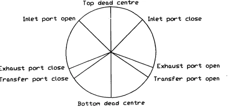
The geometric characteristics of a crankcase compressed, loop-scavenged Schnurle-type two-stroke I.C. engine are illustrated below. The opening and closing timing of various
engine ports are symmetrical with respect to bottom dead centre (BDC), Fig. 2.1. The scavenging ports, A-C and A'-C', are symmetrically located at the same level on both sides of the exhaust port, Fig. 2.2(a)(b). The principle of operation is explained with reference to Fig. 1.1. As the piston travels upward toward the top dead centre (TDC), the inlet port is opened (IPO) by the piston skirt. Fresh charge enters into the crankcase through the inlet pipe, while the contents of the cylinder are compressed. Combustion is initiated just before T D C of the stroke leading to a significant increase of the cylinder gas pressure and temperature. The high pressure gas forces the piston downward toward bottom dead centre. Some of the fresh charge may escape to the environment through the inlet port when the crankcase volume is reduced (back flow). After this the inlet port closes (IPC) and the fresh charge in the crankcase is compressed.
Top dead centre
Inlet port open / ^ . Inlet port close
Exhaust port close W^X N^W Exhaust port open
Transfer port close \^ y Transfer port open Bottom dead centre
(a)
CLEARANCE
HEIGHT
±
^
PISTON FACE
AT TDC
CYLINDER HEAD
XZM
CMC) B' A'
PISTON FACE AT BDC
(b)
The gas exchange period begins as the exhaust port is opened ( E P O ) . During this period the products of combustion are replaced by a fresh charge. In a carburetted engine the fresh charge consists of a mixture of fuel and air. This period m a y be divided into t w o sub-periods:
1) the exhaust blow down period - from the exhaust port open (EPO) to the transfer port open ( T P O ) , and
2) the scavenging period - from the transfer port open ( T P O ) until the exhaust port close (EPC).
During the scavenging period, the compressed fresh charge in the crankcase flows through the transfer ducts into the cylinder and replenishes the combustion products through the exhaust port. The process is controlled by a pressure gradient across the cylinder, which governs the simultaneous inflow and outflow streams through the opened transfer and exhaust ports. A s the piston passes B D C and travels upward, the crankcase volume increases, and another back flow from the cylinder to the crankcase through the transfer port m a y occur. After the transfer ports are closed (TPC), the fresh charge m a y escape through the exhaust port during the period T P C - E P C . In a conventional symmetrically timed two stroke engine where the opening and closing crank angle for each port is fixed and symmetrical with respect to the B D C , the T P C - E P C period is as long as the b l o w d o w n period. This is sufficiently long to lower the cylinder pressure at E P C with a corresponding decrease of engine performance due to a shortage of air/fuel mixture.
2.2 Definitions and Terminology
parameters such as scavenging efficiency, charging efficiency, trapping efficiency and delivery ratio are employed to evaluate the effectiveness of this process. Their definitions follow the SAE Handbook[10]:
scavenging efficiency r\t:
m
1, — (2.1)
W ^ + Wv
trapping efficiency r\t\
m
Hr " ~ (2.2)
charging efficiency TJ,
m
*c - — 7 T (2.3)
?V a eyl
delivery ratio kd:
m,
K - jf (2.4)
also, volumetric scavenging ratio, Xs.
T h e overall engine performance is mainly characterised by the following quantities:
brake specific fuel consumption ( B S F C ) : mf
brake m e a n effective pressure ( B M E P ) :
BMEP =
indicated mean effective pressure (IMEP): Vtn
(2.7)
<
IMEP = — - (2 8)
*
where
irif - m e a n fuel flow rate (kg/s) Pb - brake power ( k W )
P} - indicated power ( k W )
Vs - cylinder swept volume (m 3
) Vcyl - cylinder volume (m
3
) n - engine speed (rev/s)
ma - mass of supplied fresh charge trapped (kg)
mb - mass of trapped combustion residuals (kg)
m; - mass of fresh charge supplied by inlet port to the crankcase (kg) Vtr - volume of fresh charge supplied by transfer port to cylinder (m
3
) pa - ambient density (kg/m
3
)
These quantities are used to compare the performance between different engines.
2.3 Experimental and Theoretical Evaluation of the Scavenging Process
Although the qualitative description of the scavenging process is straightforward, the quantitative determination of the scavenging parameters, as defined in section 2.2, is
from exhaust gas analysis.
Accurate theoretical descriptions of the gas dynamics are m u c h more complicated. Recently, multi-dimensional computational fluid dynamic models based on the fundamental laws of mass, m o m e n t u m and energy and particular relations which govern the fluid flow in the cylinder have been established. The results of such computations have shown details of the in-cylinder flow structure and development, and its influence on the gas exchange process. A proper description of the behaviour of the scavenging process not only improves the understanding of the mechanism of the in-cylinder gas exchange process, but is also essential for predicting the combustion and overall engine performance.
2.3.1 Experimental Studies of Scavenging
The internal mechanism of the gas exchange process and the improvement of the
scavenging quality for a particular engine cylinder can be investigated by model testing. M a n y of the methods are based on flow visualisation which employ coloured liquids as tracers in "wet" tests and smoke or other visible particles in "dry" tests. S o m e original methods have been developed by Dedeoglu [11], O k a et al [12], Rizk [13], Ohigashi [14], Ohigashi [15] and Phatak [16].
Oka et al [12] investigated the relation between the scavenging flow of a looped two-stroke engine and its efficiency. Water in a transparent cylinder w a s scavenged by injection of dyed salt water. The specific gravity of the contents of the cylinder after scavenging w a s measured to calculate the scavenging efficiency. The authors concluded that the scavenging efficiency changes continuously with the delivery ratio, and the deterioration of scavenging efficiency w a s caused mainly by the short circuiting loss.
Martini and Oggero [17] employed a mixture of air and helium to simulate the burnt gases, while pure air w a s used as the fresh entering charge. Quantitative evaluation of the
measured the flow field inside a cylinder during the gas exchange period by using a motored Schnurle-type two-stroke engine and a hot-wire anemometry technique. A complete velocity field and turbulence parameter m a p has been generated for various operating conditions. These m a p s were used to study the effects of engine speed, throttle position and piston head shape.
Jante[19] proposed a technique for the improvement of the scavenging process in a particular t w o stroke engine cylinder. H e found that the most efficient scavenging for a
given cylinder can be obtained by designing the transfer ports according to tests with the cylinder head removed. T h e experimental apparatus described by Jante is illustrated in Fig. 2.3.
PITOT TUBES CONNECTED TO THE RECORDING INSTRUMENTATION
COMB OF PITOT TUBES
ENGINE WITH TEST CYLINDER £ BEING MOTORED —*• /«£
matt
EXHAUST PORT
INLET PORT
Fig. 2.3 T h e Jante Test Rig [8]
T h e engine without its cylinder head is motored at a constant speed. A number of Pitot tubes are located at the face of the cylinder head to measure the distribution of the scavenging air velocity just above the open cylinder. Based on the velocity contour so
"The scavenging currents must so interact with the piston crown and the cylinder wall that a stable closed rising current is obtained on the wall opposite to the exhaust ports, which has its m a x i m u m velocity at this wall and near zero velocities on the line perpendicular to plane of symmetry and the cylinder axis.", See Fig. 2.4.
Cylinder Zylinder 4 8 0 ' = 18,9"bore h=65 m m W S = 2,56" woter kolben im U.T. (d) Piston in BOC
Fig. 2.4 Velocity contour of an optimum cylinder by Jante method [19]
The Jante method has proved to be an effective design tool over the past three decades and is still in use today, as reported by Ishihara et al [20,21,22,23]. However, this method provides no quantitative information about the constitution of the cylinder contents during the gas exchange period.
2.3.2 Theoretical Modelling of the Scavenging Process
A reliable theoretical model of the gas exchange process in a two-stroke engine is a powerful tool for engine design and development. The optimisation of the geometry of a cylinder and ports system can be achieved with the help of a computational fluid dynamics model ( C F D model). T o predict the overall characteristics of a given engine under different operating conditions, a C F D model m a y be employed, however, a simple relation which describes the scavenging efficiency and volumetric scavenging ratio characteristics is often preferable.
2.3.2.1 Computational Fluid Dynamics Model
The best description of the scavenging process is obtained if the complete set of the partial differential equations which govern this process are solved to yield the time variation of
the spatial profiles of the dependent variables, such as pressure, density, enthalpy, velocity and concentration of fresh charge, see Ahmadi-Berrui et al[TT\ and Schwarz[28]. These equations usually include the conservation laws of mass, m o m e n t u m and energy, turbulence model, relations between transport coefficients and dependent variables, some additional auxiliary state equations (such as the isentropic and perfect gas laws) and the corresponding initial and boundary conditions. The C F D models are useful in providing a descriptive picture of the in-cylinder events, and identifying areas such as fresh mixture concentration, short circuiting and poorly scavenged regions for a given configuration of a cylinder and port assembly. Their applications to two-stroke engines have also led to significant progress in understanding of the gas exchange process. The optimisation of port timing and shape based on the extensive information provided by C F D models is possible and a great deal of time m a y be saved w h e n compared to trial and error approaches.
in-cylinder flow structure and its development, as well as the influence of pressure w a v e oscillations in the scavenging port and exhaust port system on the in-cylinder flow processes. T h e cylinder has the port arrangement similar to Fig. 2.2(a). T h e calculation d o m a i n w a s confined to half the cylinder volume, partitioned by the geometrical plane of symmetry. T h e thermodynamic initial and the instantaneous boundary conditions in the scavenging and exhaust ports were pre-calculated by the authors using a separate unsteady gas dynamics model [29] to enable incorporation of the effect of the pressure waves which causes strong flow oscillations in the scavenge and exhaust ports. The instantaneous mass
flows for the individual scavenging ports were proportional to their flow areas. Uniform and plug flow were assumed for time-dependent velocities and mass flow rates of the inflow streams at the scavenging ports. T h e main findings of the w o r k were:
(1). The basic in-cylinder flow structure, established early during the scavenging phase, comprises a three dimensional "loop" flow, Fig. 2.5(a), and a pair of toroidal
vortices s h o w n in Fig. 2.5(b).
REFERENCE VECTOR
P * 211.6 M/S
II i i / / / / « > • « » % « -t
• ii jftcctccect: *** * ******•—
«-*.N
H S V \ \
I U / ///••**•—**^^^\
4&
pgtmmf. i mtWFtmm
+0W*r* » I I I I I I
«^ M 4 M
exhaust
port E
• • • • • • r
W W W W W W W * « "
\\\\\\\\\\WWtin
**^\\\\\WWttW
•«*t***»Jv<\\\\^m\\TN
scavenging
port C
II I 4 4 44 4 / • • • • « ' .
'...tatzzzzs.*
'--~>\\
N \ \
•mumuu»F^\\
M »//|
< » / 1
M M M M I i m M * ^ . II | | M M i . . »
scavenging
port A
1 « : :
111 . • •
« « » t k % t l l 1 1 1
1 1 1 1 1 1 i I II
\\\^n« « « u m 11 II
tun Hi
^\\\\\^-"///// 4 Hi \\\\\\\**~ •!
• i M » » « * < ^ < 4 .
scavenging
port B
(b)
• 195.9 H/S
\l • • • / / / i i — ,
| J J J < I • > » - ">•//<«»*•<
H
t i i » . . . ' / / •
"'r/rrrrrs// A**
» « • » » • i » m W / / / / /
...P.... .m^W/V i fT »»^V/V/
• P > • w i • i
• ^ W / " •» • i n i n i i
•. . t %*SS
.» . i i m i n . i m i v /
exhaust
port E
-•»•»**••//ft! Ml M 111
/Wv*» •vr / ;i
/ / / / / • • • » » <• ^ » i
scavenging
portC
(c)
2.5 In-cylinder velocity field at various crank angles
(2). T h e vortex structure w a s responsible for the impairment of the scavenging efficiency.
(3). The flow and the scavenging process were markedly affected by the pressure wave oscillations in the scavenging system, Fig. 2.5(c). T h e in-cylinder flow structure and charge distribution pattern established during the normal scavenging phase w e r e significantly altered as a result of the oscillations of the intake and exhaust mass charge and discharge.
Recent research efforts using laser doppler velocimetry (LDV), for example, by Smyth et
al [30] have found that the direction of inflow jets, particularly for the main transfer ports,
deviated from the design direction of the port such that the plug flow assumption w a s inadequate. Moreover, the thermodynamic properties in the cylinder and at the ports (first node in pipes) were closely interdependent. Therefore, a better w a y to conduct this simulation is to execute iteratively the unsteady gas-dynamics program and the C F D program, that is, at each time step, solve the coupled in-cylinder equations and port boundary equations given by the pipe flow model. This m a y be computational intensive and would be prohibitive in terms of run time on anything other than a supercomputer.
2.3.2.2 Simple Theoretical Scavenging Model
Although a detailed computational fluid dynamics model can provide extensive
information about in-cylinder flow patterns, the computation time for such a simulation can be huge. Therefore, such a model is considered impractical for engine modellers w h o wish to predict the overall performance characteristics of a given engine configuration under different operating conditions. For the later purpose, the relatively simple theoretical model which correlates the scavenging efficiency r\s against the volumetric
scavenging ratio X. (or other similar parameters) is preferable.
on the assumptions that the replacement of products of combustion can be modelled by so called displacement scavenging, mixing scavenging, or a combination of both. In addition, s o m e of the fresh air-fuel mixture m a y directly by-pass through the cylinder into the exhaust pipe and be wasted (short-circuiting). T h e following scavenging models can be found in literature.
(1) Perfect Displacement Model:
The idealised perfect displacement model apparently conceived by Hopkinson as
stated by Blair[8] implies that the products of combustion are completely replaced by the fresh charge under constant cylinder volume, temperature and pressure, and there is no escape of fresh charge through the exhaust port. It is the upper bound efficiency for the scavenging process and the real process is never as efficient.
(2) Perfect Mixing Model:
The second notion conceived by Hopkinson about the way the cylinder was
scavenged w a s perfect mixing. In a perfect mixing model, the scavenging process also occurs at constant cylinder volume and pressure. A s the fresh charge enters the cylinder via the transfer ports, it is assumed that it instantaneously mixes with the cylinder contents to form a homogeneous mixture. The exhaust gas is therefore a mixture of combustible waste and fresh charge. For a modern two-stroke engine, the perfect mixing model underestimates the scavenging performance. However, it is still frequently quoted as a reference for comparison. Fig. 2.6 shows the r\. - X. characteristics for perfect displacement and perfect mixing scavenging.
(3) T h e Combined Models:
Experimental modelling of the scavenging process using flow visualisation rigs by Dedeoglu [11] and Sher [31] revealed that the scavenging process m a y be depicted as proceeding in two or three principal phases: displacement, mixing and short-circuiting. Consideration of the actual process of scavenging led to the development of the multi-zone model. In such models the cylinder is subdivided into two, three or m o r e zones. Fresh charge, burnt gas and the mixture of fresh charge and burnt gas occupies different zones. S o m e notable multi-zone models are: the isothermal two-zone model of Maekawa[32], the two-zone model of B e n s o n and Brandham[33], the "S" shape model of Sher[34], and the scavenging
model of Blair[8].
1
-0)0.8
perfect displ
perfect mixing
0.4 0.6 0.8 1 1.2
scavenging ratio
Fig. 2.6 r\s- Xs Characteristics for perfect scavenging
W h e n the volumetric scavenging ratio reaches a certain level, the undiluted fresh charge in the perfect displacement zone together with the incoming stream of fresh charge instantaneously mix with the remaining burnt gas in the cylinder to form a homogeneous mixture. T h e substance directed to the exhaust port is switched from pure burnt gas to this h o m o g e n e o u s mixture. T h e resulting scavenging efficiency-scavenging ratio relation is:
tl,»l-(l-x)c*p{x-(l-j»X} (2.9)
where x - the scavenging ratio at the transition point y - the proportion of short-circuiting
X s - the scavenging ratio T|s - the scavenging efficiency
Re-arranging equation (2.9) gives:
In(l-Tl,) = (y-1H + ln(l-x)+ x (2.10)
This equation represents a straight line in the ln(l-ri5) - X. plane. The slope is (y-1) and the intercept is ln(l-x)+x. In Benson's model, it is apparent that the slope (y-1) could not be
less than -1, as that would produce a negative value of short circuiting ratio y, which is physically impossible.
The experimental justification for such classical scavenging models is scant. Information of this kind w a s not available until the 1980's and probably the most appropriate experiments
apparatus is able to provide verification of all theoretical scavenging models which are postulated under the constant volume, isobaric and isothermal assumption. M o r e information on the Q U B single cycle test rig m a y be found in Appendix A.
Blair et al [38] did extensive investigations on modelling the scavenging process with the aid of the single cycle gas scavenging rig. B y means of measurements of the scavenging characteristics of a number of testing cylinders, the authors concluded that the measured scavenging efficiencies and scavenging ratios, w h e n plotted as ln(l-T|s) vs. X., do fall on straight lines. However, the slopes of these straight lines are all less than -1, which is in conflict with the Benson-Brandham theory. Moreover, the better the scavenging, the closer the value is to -2. This 1988 finding demonstrates that the Benson-Brandham scavenging model fails to correlate with relevant experiments. The reason is that the "step change" assumptions are not realistic in real scavenging processes.
The "S" shape scavenging model developed by Sher[34] is based on the observation, that the plot of mass fraction of fresh charge being detected in the exhaust gas passing through the exhaust port versus time, exhibits a "S" shape curve. B y using an exponential function to fit this "S" shape curve, a mathematical relation for scavenging efficiency w a s derived. T h e model interprets the scavenging process as a superposition of a perfect displacement and a charging loss. Examination of the scavenging process in flow visualisation rigs revealed that there w a s no occurrence of an abrupt transition from one phase to another(step change), but rather a complex combination of the perfect displacement, perfect mixing and short-circuiting. Introducing a term which accounts for charging loss gives a m o r e realistic correlation.
After the experimental refutation of the Benson-Brandham model, Blair [38] also
variation of the proportions of perfect scavenging and short-circuiting are regarded as functions of scavenging ratio. At any given level of scavenging ratio, a certain amount of the increment of the entering fresh charge is going to be short-circuited, while the remainder of the entering fresh charge goes into the perfect scavenging volume. For the charge which enters the perfect scavenging volume, a proportion of the total stays, and the rest joins the perfect mixing zone.
The ratio of the short-circuiting, perfect displacement and perfect mixing of the entering fresh charge increment are supposed to vary linearly as the scavenging ratio increases. The calculation proceeds to enter fresh charge volume increment as 1, up to any desired m a x i m u m value, with the cylinder volume set at 1000. T h e volumetric distributions of each distinctive portion are traced and accumulated at the end of every charging step. The resulting instantaneous scavenging efficiency and trapping efficiency are therefore based on these quantities.
According to the author, the model is relatively simple to "tune" for a particular engine cylinder, as there are usually only two parameters to be manipulated in order to achieve a good correlation with experiment. The model, after the correlation is achieved, provides preliminary information regarding the relative contributions of perfect displacement, perfect mixing or short-circuiting during the scavenging period for a tested cylinder. It is also interesting to note that by using Blair's model, the predicted exhaust gas purity versus time for different cylinders w h o s e scavenging qualities have been ranked by experiments, s h o w a m o r e or less "S" shape profile, the m o r e "S" like the profile the better the scavenging is, which is in line with Sher's finding described above.
2.4 I m p r o v e m e n t of the Scavenging Process
The ideal scavenging process for a simple naturally aspired, crankcase-scavenged two-stroke engine has already been described as the perfect displacement process in which the entering fresh charge acts as a piston to push the burnt gases out of the cylinder without actually mixing with them and no fresh charge escapes from the exhaust port. H o w e v e r a carburetted two-stroke engine loses between 1 5 % - 2 0 % of the fuel under normal operating conditions, Sher [2].
This is attributed to the fresh charge short-circuiting to the exhaust and back flow through the inlet and transfer ports. It results in high hydrocarbon emission levels, poor fuel
economy, low performance figures and a wide spread of cycle to cycle variation. A s the port timing and the pulsating effect of pressure waves in the intake and exhaust system are optimised to offer the best match with the engine at some well defined operating condition, the occurrence of short-circuiting, back flow and leakage through the exhaust port m a y have significant deleterious effects at off-design engine speeds or partial-open-throttle positions. It causes reduced engine performance characteristics, worse fuel economy and higher emission levels.
To overcome these shortcomings of the two-stroke engine, many approaches have been proposed. A m o n g these, the non-symmetrical arrangement of the port timing has proved to be one of the m o r e effective. The introduction of direct fuel injection systems and multi-stage scavenging activity also produces positive results.
2.4.1 Non-symmetric Port Timing
The installation of a reed valve, a rotary disk valve, a fluid diode or a scroll diode on the inlet or transfer port have been reported. A fluid diode is a chamber with no moving parts
vorticity development. Nagao, et al [41] examined experimentally the presence of the scroll diode and the vortex diode at the inlet port on a motored engine. They claimed that the delivery ratio w a s increased considerably at low engine speeds with the installation of a scroll diode. T h e scroll diode w a s found to be more effective than the other types of diodes. Sher[42] studied the performance characteristic of a fired two-stroke engine with a scroll diode at the inlet port and found the engine torque w a s impressively improved by 3 0 % at low engine speeds, while it deteriorated , by 2 0 % , at higher engine speeds. A possible cause is that the diode generates high forward resistance at higher engine speeds
and the delivery ratio consequently deteriorates.
A scroll diode was also installed in the scavenging port by Sher[43], and the influence of the diode presence on the engine performance w a s examined under the fired condition test.
T h e torque curve becomes flatter while its m a x i m u m value appears slightly above the original curve at the same engine speeds. The improvement in the engine power achieved with the diode seems to be most significant near the lower and higher limits of the engine speeds. T h e increment m a y be high as 2 0 % . A close examination of the cylinder and crankcase pressure history shows that at low engine speeds, the crankcase pressure is higher than the cylinder pressure at T P O , and the burnt gases are scavenged through the exhaust port by the fresh charge.
When the piston passes the BDC and moves upward, the crankcase volume increases while the pressure there is already low. The back flow from the cylinder to the crankcase through the transfer port in a simple engine occurs w h e n the crankcase pressure is lower than the cylinder pressure. Consequently, the crankcase pressure m a y reach a higher value at T P C . With a scroll diode located at the transfer ports, the crankcase pressure record shows that the pressure at T P C remains at a lower value, which means that a back flow has been suppressed. At high engine speeds, the pressure inside the cylinder at T P O is still high and the crankcase pressure in a simple engine increases steeply due to the back flow, while in the diode-installed engine the crankcase pressure increases moderately which suggests that the backward flow has been reduced.
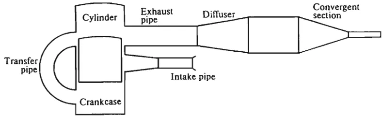
loop-scavenged, two-stroke engine under off-design conditions is to control the pressure at the exhaust port by changing the exhaust pipe configuration. Dynamically, controlling the exhaust pressure at the port has a similar effect to modification of the port timing device, so an improved scavenging quality is achieved by the introduction of non-symmetric port timing. Changing the dimension of a particular section of the exhaust pipe is found to be an effective and practical method to improve two-stroke engine performance
characteristics under off-design conditions. Fig. 2.7 depicts such an exhaust system.
Transfer pipe
Convergent section
Fig. 2.7 A n extendable exhaust configuration
When the exhaust port opens a pressure wave is transmitted down the exhaust pipe. This pulse is partially reflected by the diffuser as a negative (expansion) w a v e and partially transmitted. T h e expansion wave, on reaching the exhaust port, will assist scavenging of the cylinder by "drawing" gas through the exhaust ports. T h e transmitted pressure w a v e will eventually reach the converging section of the exhaust pipe and will be partially reflected and partially transmitted to atmosphere. T h e reflected positive (compression) pressure w a v e arrives back at the exhaust port to create a "blocking effect" in the T P C -E P C period. T h e working principle described, being translated into the pressure history at
the exhaust port, is illustrated in Fig. 2.8.
Clearly a particular geometry will be optimal for only one engine speed, so it is necessary
various operating conditions. Detailed theoretical and experimental studies of an extendable exhaust constitute the core of this project and are presented in later chapters.
,
/ B l o w \ / d o w n \ / pulse \
Rarefaction reflected from di (Tuser
Plugging pulse reflected from convergent section
r-
pressure*>•
epo tpo bdc tpc epc tpo—transfer port opens tpc—transfer port closes
Fig. 2.8 Ideal dynamic pressure history at exhaust port [44]
2.4.2 Stratified C h a r g i n g
Several other attempts have been m a d e to overcome the drawbacks of a two-stroke engine by considering that the scavenging process should be carried out fully or at least partially with air alone instead of an air-fuel mixture. For this, efforts have been m a d e in t w o parallel directions, the introduction of fuel by an injection system and the multi-staging of
scavenging.
proceeds in t w o steps: the fresh air replaces the combustible products and then the fresh fuel-air mixture fills the cylinder. Considerable reduction in fuel consumption and exhaust emissions have been reported by employing such systems.
Fresh charge losses can be reduced by the selective exhaust gas recirculation (SEGR) method, developed by Saxena [45]. Investigations of fresh charge losses in the exhaust port showed that the H C concentration history decreases during the initial period of scavenging and the deepest trough appears between T P O and B D C . It then increases to a m a x i m u m level and practically remains constant around top-dead-centre or during the exhaust port closure. The S E G R method is based on this effect where the portion of the exhaust gases corresponding to the period it contains m a x i m u m H C concentration can be recirculated to aid scavenging the cylinder. A s this period corresponds to the induction phase of engine operation, the crankcase suction can be used to draw this high H C concentration exhaust gas near the exhaust port. The induction system of the S E G R engine consists of two circuits. The primary circuit is similar to that of the conventional engine and supplies carburetted air-fuel mixture. The secondary circuit consists of a probe in the exhaust port connected to the upper part of the transfer passage through a reed-valve.
The operating principle of SEGR is: during the scavenging process, the recirculated exhaust gas enters the cylinder first and briefly scavenges the cylinder, and the fresh mixture from the crankcase flows to the transfer ports and starts to charge the cylinder subsequently. The influence of S E G R on emission and brake specific fuel consumption ( B S F C ) is quite pronounced. A reduction of 3 4 % on H C emission and 1 2 % on B S F C has been claimed. However, as the performance of a S E G R engine is dependent on the recirculation ratio, the air-fuel ratio, and the spark advance (due to the higher exhaust residual found at the commencement of compression), the S E G R system is not only complex in structure, but also complicated in operation.
words, the scavenging air volume is an important factor in successful scavenging of the cylinder. This observation leads to the idea that the temperature of the fresh charge can be increased in order to obtained a better scavenging efficiency. However, the lowered density implies that less fresh charge will be trapped in the cylinder w h e n the compression commences. Dedeoglu et a/[39] suggested a two-stage scavenging model to improve the overall engine efficiency.
In the first stage of the scavenging process, a certain portion of the charge is warmed in a heat exchanger by exhaust gas as it is led into the cylinder. The charge expands in the
CHAPTER 3
THEORETICAL CONSIDERATIONS
AND DEVELOPMENT OF MODELLING A TWO-STROKE ENGINE
3.1 Introduction
Successful numerical modelling of a two-stroke internal combustion engine is highly dependent upon being able to model the compressible gas flows in the intake, transfer and exhaust pipes. A s the timing of pressure w a v e arrival and departure at the exhaust port is critical to the performance of an engine equipped with a "tuned" exhaust pipe, an accurate model of the gas flow in this pipe is essential. Wallace et al [40,46], Benson [47] and Blair et al [8,48,49] have investigated this problem and concluded that quasi-one dimensional
gas flow models which assume slowly varying pipe cross section and isentropic conditions are adequate.
Although pipe friction and heat transfer through the wall of the pipe are present, these effects are small by comparison with energy transport in the flow direction (especially
w h e n the pipe wall is insulated) and have been neglected in many previous studies. This study will m a k e the same assumptions. In this chapter, the equations which govern such a flow are formulated and the solution procedures are derived. Different schemes to evaluate the variation of Riemann variables along the characteristic curves are proposed. Efforts are also m a d e to properly evaluate the pressure wave reflection at engine port/pipe boundaries.
3.2 Fundamentals of Pressure Wave Theory
3.2.1 Basic Concepts
-500 m/s) through the surrounding gas, in general suffering reflection, rarefaction and attenuation. A n example of a pressure w a v e (the propagation of a physical disturbance) is a sound w a v e (acoustic pressure wave), where the pressure amplitude of the w a v e is very small. A n y pressure w a v e with a pressure amplitude greater than an acoustic w a v e is classified as finite amplitude wave. Its magnitude is often measured by t w o dimensionless parameters, namely:
Pressure ratio:
(3 1)
and pressure amplitude ratio:
X =
/ \ P_
T-l 2Y
(3.2)
where p is the pressure at the point under consideration, p0 is the undisturbed or
reference pressure and y is the specific heat ratio of the gas.
Two types of pressure wave exist: compression waves and expansion waves. A
compression w a v e occurs w h e n the pressure ratio T is greater than 1 everywhere on the
wave. T h e gas particle is moving in the same direction as the w a v e being propagated. A n expansion w a v e exists w h e n the pressure ratio W is less than 1 everywhere on the wave. T h e gas particle is moving in the opposite direction to the direction of w a v e propagation. Fig. 3.1 illustrates both types of w a v e profiles. A w a v e profile is obtained by taking the
pressure ratio F a t different values of distance x along the pipe at a fixed time.
p/po
1.0
a) Compression w a v e propagates rightward
p/po
1.0
b) Expansion w a v e propagates rightward
Fig. 3.1 A pressure w a v e profile
reference pressure p0 and density p0, Bannister [50] has s h o w n that the gas particle
velocity u is:
_2_ Y-1
u = a0{X - I, (3.3)
where
ao - the reference sound velocity
h = \fy~R
T0 - reference temperature
X - pressure amplitude ratio
Y - specific heat ratio of gas R - characteristic gas constant
The wave propagation velocity c:
(3.4)
c = - J L ^ v + i ^ - 2}
Y-1
(3.5)
Local sound velocity:
a = - \ 1
= ao
V T
\ To
\
P_ Y-1
2Y a
oX
(3.6)
Local gas density:
P = Pt
/ \ P_ Y
- P^
Y_1 (3.7)Po •
Po
(3.8)
Local mass flow rate:
/
m = puA = uA \po
2_
(3.9)
where A represents the flow passage area.
Local gas particle M a c h number:
M = * = JL
a aJC
(3.10)Equations (3.3)~(3.10) are identically applicable to an expansion wave. The negative sign of the gas particle velocity u (equation 3.3), as a result of X < 1 , only signifies that the particle is moving oppositely to the wave propagation direction.
3.2.2 Superposition of Pressure W a v e s
As the outward moving exhaust pulse (compression pressure wave) arrives at the pipe exit, w a v e reflection occurs. The reflected pressure wave reverses its direction of propagation and will superimpose on the continuously outward running exhaust pulse. The reflections of pressure waves also occur at port/pipe interfaces and at any change of pipe diameter. Therefore at virtually all times except the very first cycle of engine operation, where the gas in the exhaust pipe is undisturbed, pressure waves propagate to and fro through each other because of wave reflections.
considering simple w a v e s R W and L W , the gas particle velocity at point R on w a v e R W , and the particle velocity at point L o n w a v e L W , are, from equation (3.3) :
2a„
u R,E
z?*-h
u
2a0
v - 1 ^ 1]
Subscript E (earth) denotes that such velocity is relative to the stationary pipe wall, that is, absolute velocity.
Zfl
displacement
(a) Before superposition
Z 4 £ 2
-cf
2"
Q_
1.8
1.4-1.2 •
1 •
t =
= t,
/RW
\ f*\l
\t>
Vi
* •*
LW \
10
displacement
(b) During superpositionSuppose points R and L are n o w coincident during superposition. The observer R w h o
m o v e s with w a v e point R, upon entering the wave L W , will m o v e with a velocity relative
to observer L (who is sitting on wave point L), denoted as u^
L,
la,
u
RJ,Y-1
\
PLJ
* -1
2a„
-r/.-x*
(3.11)
where p, is the superposition pressure.
Superposition velocity (absolute velocity) at point R, u^
tE)s, becomes the summation of
u
RLand u
UE:
l
(R,E)s ~ UR,L + UL,E
2a
o „ „
2ao
- L
Y
Y-1
(3.12)
•(*. ~^L*h
Similarly, observer L w h o sits on wave point L is entering wave ( R W ) and will travel with
a velocity relative to observer R on wave point R, u
L R, during the superposition
% *
Y-1
2a„
' / > /
\PR)
2Y _
7*
- x.
*)(3.13)
The superposition velocity at point L, \i
(LE)s, is therefore:
l(L,E)s ULJl + UR,E 2O
0 v „
2tI
0
Y
ii
Y-1
" f ^ " * * >
+
TT^
- L
,-Z
+2 ^ - 1,
(3.14)
A s point R and point L from wave R W and L W respectively are n o w coincident, u ^ ^
4pressure amplitude ratio, X,:
*.-Z*+XL-1 (3.15)
Substituting equation (3.15) into (3.12) gives the superposition particle velocity, u
2an
u =
7 f (** "
XL)
= UR,B + ULJt
(3.16)
that is, the particle velocities can be directly s u m m e d up to obtain the superposition particle velocity during w a v e superposition.
The absolute velocity of propagation of point R during superposition becomes the sum of the local acoustic and particle velocities corresponding to X „
c0 = a + u
2an
= a,
'<?'
+Z~^
XR'
xv
= ar
Y+l
I Y-1
*R+ X. - 1
to right (3.17)
Similarly, for point L:
C
L = -a + u
2a„
" V , + 7XR ' X
L)
Y-1 = -ar
'y + 1?
X
L +
Y-3 Y-U
Xn - 1
to left (3.18)
3.2.3 Reflection of Pressure W a v e at Port/Pipe Boundary
rise to a pressure pulse which is reflected at the open end of the exhaust pipe and returns to the port as a rarefaction w a v e or scavenging wave. T h e arrival of this rarefaction w a v e at the exhaust port, if it takes place before port closure, leads to renewed discharge of gas from the cylinder, where a pronounced pressure drop occurs as a result. At the same time the rarefaction w a v e is reflected at the port with the port acting as a partially open or closed end. Fig. 3.3 illustrates such a pressure w a v e reflection process in an exhaust pipe. T h e arrival and the reflected outgoing waves have pressure ratios pjp0 and pjp0,
respectively.
\ Pu I Po
Exhaust Pipe
Pi2IPo
Atmosphere V o l u m e = oo Po> a0, T0
Prl I PO
Fig. 3.3 Reflection of pressure w a v e at pipe boundary
The flow through the two-stroke engine ports may be analysed on a steady-flow basis. This is because of the fact that the local changes of pressure, density and velocity at the ports are very large compared with changes in time. T h e partial derivatives with respect to distance are m u c h larger then the corresponding partial derivatives with respect to time. Therefore the time derivative m a y be neglected and the flow process can be considered as one dimensional and steady.
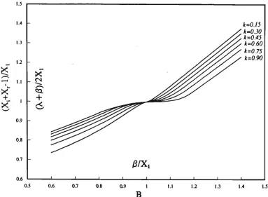
port/pipe interface. B y applying the fundamental laws of continuity, m o m e n t u m and energy and taking the different pressure assumptions at the vena contracta, four sets of equations are derived for the four distinctive flow situations, namely the subsonic outflow, the subsonic inflow, the sonic outflow and the sonic inflow. The solutions of these equations shows that the magnitude of the reflected pressure wave, pjp0 (XJXQ), is
dependent on two independent parameters, namely,
(1). the group:
B =
Y-1
2 ' - l
( P ^
\P>J
Y-1 2Y
or
B = 2Xr\
Xt
(2). the instantaneous effective port/pipe area ratio k.
px and p correspond to the instantaneous cylinder pressure and incident wave pressure,
respectively.
For the flow at the pipe exit, the atmosphere may be considered as a cylinder with infinite volume. B is thus reduced to:
B = 2X
r\
and, if the pipe exit is not throttled, then k=l.
![Fig. 2.3 The Jante Test Rig [8]](https://thumb-us.123doks.com/thumbv2/123dok_us/7942687.1318467/26.568.184.435.314.600/fig-the-jante-test-rig.webp)
![Fig. 2.4 Velocity contour of an optimum cylinder by Jante method [19]](https://thumb-us.123doks.com/thumbv2/123dok_us/7942687.1318467/27.568.159.422.171.393/fig-velocity-contour-optimum-cylinder-jante-method.webp)

![Fig. 2.8 Ideal dynamic pressure history at exhaust port [44]](https://thumb-us.123doks.com/thumbv2/123dok_us/7942687.1318467/40.568.101.447.103.340/fig-ideal-dynamic-pressure-history-exhaust-port.webp)