Technical Bulletin
726+,%$
4031061
Strata DK424 Release 4.15 Software and Features
This bulletin lists the new features added to the Strata DK424 system in software Release 4.15 and
summarizes the programming changes. This bulletin also includes guidelines for programming Integrated
Services Digital Networking (ISDN) calls. The Call-by-Call feature is included in Release 4.15 and a brief
overview of how this feature works appears at the end of this bulletin.
Upgrade Instructions
Technical Bulletin TBDK-0034 provides instructions for upgrading RCTU processor Printed Circuit
Boards (PCB) containing Release 3.x, Release 4.0 or Release 4.1 software to Release 4.15. TBDK-0034 is
included with the ROM upgrade kit.
Release 4.15 Programs and Features
Release 4.15 contains enhancements to the Primary Rate Interface (PRI) service currently available in the
Strata DK424. This includes the ability to reserve channels for multiple Dialed Number Identification
Service (DNIS) numbers, such as order entry centers, and the ability to provide incoming call access at all
times. The enhanced Call-by-Call feature enables incoming call overflow and outgoing call Least Cost
Routing (LCR) routing between trunk groups to provide full access. Another added feature is the ability for
an LCD display to show a calling party’s identity when the phone is busy on another call.
The following feature enhancements are available in Release 4.15. Refer to sales bulletin
SBDK-0049
for
detailed explanations of these features.
ISDN Programming Guidelines
The following tables provide guidelines for programming various ISDN calling features.
Programming for ISDN CO Switch Type
Determine which type of CO switch is providing the PRI service and set the following programs
accordingly. (This is not necessary for Basic Rate Interface (BRI) service.) Most Northern Telecom
DMS ISDN switches follow Northern Telecom’s PRI custom protocol, sometimes referred to as National
ISDN Stardard 1 (NI1). However, some DMS ISDN switches are National ISDN Stardard 2 (NI2). Most
all ISDN switches manufactured by other companies follow the NI2 standard.
Software Item Description Program Number
Enhanced Call-by-Call with Min/Max Control
*
67-3,*
67-4 Enhanced Call-by-Call with Time Zone Assignments*
67-5 Calling Number Identification Service (CNIS) Enhanced Function*
68,*
69Trunk Group Corresponding to Listed Directory Number (LDN) Code
See “Programming for ISDN PRI LDN Type Call” on Page 5.
“Start” Function Programmable in LCR for Immediate Dialing 55-1 Non-Facility Associated Signaling (NFAS)
*
43-1~3Call Waiting LCD Display None
Upload/download Call Forward to Attendant Problem Fix (Attendant
= port 999) None
Standard Telephone retrieves its own held secondary appearance 10-4, LED 15 CO dial tone after LCR access (No/Yes selection) 50-1, Key 10 DMS custom (progress ID = 81)/or all other switches = NI2=83)
*
66-3, LED 13 DMS custom or all other switches NI2 (progress indicatorsuppressed to DMS custom, NI1)
*
66-3, LED 14 PRI DMS custom (NI1) or PRI NI2 standard (*
66-3, LED 11 must beOff)
*
66-3, LED 15ISDN sub-address key (DKT/EKT/ATTD) Console 39, Code 467 PC-ATT display/Traditional ATT 58-2x, LED 04 Route unknown number or call type on ISDN incoming calls 10-4, LED 09 Call Waiting (2nd Call) LCD Display None
Program DMS Custom Switch NI2 Switches
*
66-3LED 11 OFF LED 11 ON
LED 13 ON, Progress ID 81 LED 13 OFF, Progress ID 83 LED 14 ON LED 14 OFF, Progress ID
P
re
lim
in
ary
a
n
d
Co
n
fi
d
en
ti
al
Programming for ISDN PRI DID Type Call
The following table shows the minimum programming needed to make DID-type ISDN PRI calls work in
the Strata DK424 System with Release 4.15 software.
Program
Number Program Data Description
03 XX 79 XX equals the slot in the DK system where the RPTU PCB is placed.
10-4 LED 9 ON LDN registration will function with unknown number or call type in numbering plan.
*
16 01 2 This tells the system that trunk group 01 is an ISDN PRI Trunk Group.*
42 1 XX 1This tells the system to make the ISDN PRI span the primary clocking source for the DK System. “XX” stands for the DK424 slot where the RPTU PCB is placed, and the final “1” refers to circuit 1.
*
43-1 1 1 24 This tells the system that the D-channel on the first ISDN PRI Span is the 24th channel on the PRI Span.*
63-2 04 This tells the system how long to wait to collect digits from station users making a ISDN PRI call before sending it to the network.*
64-1 LED 01 ON This tells the system to accept the incoming calls on the PRI Span as DID or DNIS Calls.*
64-2 X “X” tells the system the number of digits to look for on a DID or DNIS call.*
65-1 CO LED 001-023 ON This tells the system that there are 23 bearer channels on the first Channel Group, and that they will appear on CO lines 001~023.*
66-1 01 1 This tells the system that Trunk Group 01 is assigned to PRI Channel Group 1.*
66-301 LEDs 01-02, 11-12 ON
This tells the system that Operator calls, Carrier Access, 1+10 Digit Dialing, and Ring Back Tone to the outside caller are allowed.
01 LED 13 ON This tells the system when interfaced with DMS XXX to send the progress descriptor 81 or 83.
LED 14 ON When connecting to a DMS XXX with NI1 protocol.
LED 15 ON Set up message for outgoing call. When connecting to a DMS XXX. LED 11 must be OFF in Program *66-3 when this LED is ON.
*
66-5 1 01 XXXX This assigns the LDN/DID/DNIS number, the used as a wildcard.*
(asterisk) can be*
66-6 1 01 LEDs 01~23 ON This assigns the CO lines to the index.*
67-1 01 3 This tells the system that the PRI Span is for both-way calling.*
67-2 01 LED's 01-04 ON This tells the system to accept Speech, 3.1K Analog, 56K, and 64K type calls on the ISDN PRI Span.*
68-1 01 LED's 01-03 ON This tells the system to accept and send Calling Party Number on ISDN PRI Calls.*
68-2 01 XXX-XXX-XXXX XXX-XXX-XXXX is the number you want the system to send out on an outbound call for Caller Number Identification.*
69-1 000-344 1 00This tells the system to send the number enter in Program
*
68-2, as the Calling Party Number Identification for all stations on outbound calls.Programming for ISDN PRI DNIS Type Call
The following table shows the minimum programming needed to make DNIS-type ISDN PRI calls work in
the Strata DK424 System.
Program
Number Program Data Description
03 XX 79 XX equals the slot in the DK system where the RPTU PCB is placed.
10-4 LED 9 ON LDN registration will function with unknown number or call type in numbering plan.
*
16 01 2 This tells the system that trunk group 01 is an ISDN PRI trunk group.*
42 1 XX 1This tells the system to make the ISDN PRI Span the span the primary clocking source for the DK System. “XX” stands for the DK424 slot where the RPTU PCB is placed, and the final “1” refers to circuit 1.
*
43 1 1 24 This tells the system that the D-Channel on the 1st ISDN PRI Span is the 24th channel on the PRI Span.*
63 2 04 This tells the system how long to wait to collect digits from station users making a ISDN PRI call before sending it to the network.*
64-1 1 LED 01 ON This tells the system to except the incoming calls on the PRI Span as DID or DNIS calls.*
64-2 X “X” tells the system the number of digits to look for on a DID or DNIS call.*
65-1 CO LED 001-023 ON This tells the system that there are 23 bearer channels on the first Channel Group and that they will appear on CO lines 001~023.*
66-1 1 01 1 This tells the system that Trunk Group 01 is assigned to PRI Channel Group (1).*
66-301 LEDs 01-02, 11-12 ON
This tells the system that Operator calls, Carrier Access, 1+10 Digit Dialing, and Ring Back Tone to the outside caller are allowed.
01 LED 13 ON This tells the system when interfaced with DMS XXX to send the progress descriptor 81 or 83.
LED 14 ON When connecting to a DMS XXX with NI1 protocol.
LED 15 ON Set up message for outgoing call. When connecting to a DMS XXX. LED 11 must be OFF in Program *66-3 when this LED is ON.
*
66-5 1 01 XXXX This assigns the LDN/DID/DNIS number, the Q (asterisk) can be used as a wildcard.*
66-6 1 01 LEDs 01~23 ON This assigns the CO lines to the index.*
67-1 01 3 This tells the system that the PRI Span is for both way calling.*
67-2 01 LEDs 01-04 ON This tells the system to accept Speech, 3.1K Analog, 56K, and 64K type calls on the ISDN PRI Span.*68-1 1 01 LEDs 01-03 ON This tells the system to accept and send Calling Party Number on ISDN PRI calls.
*
68-2 01 XXX-XXX-XXXX XXX-XXX-XXXX is the number you want the system to send out on an outbound call for Caller Number Identification.*
69-1 000-344 1 00This tells the system to send the number enter in Program Q68-2, as the Calling Party Number Identification for all station on outbound calls.
17 001- 023 LEDs 03~08 ON
P
re
lim
in
ary
a
n
d
Co
n
fi
d
en
ti
al
Programming for ISDN PRI LDN Type Call
The following table shows the minimum programming needed to make LDN-type ISDN PRI calls work in
the Strata DK424 System.
71-0 000 XXXX This tells the system that the incoming DNIS number XXXX is assigned to DNIS address 000 in the DK system.
71-1 000 XXXX This tells the system to route the incoming DNIS call that was route to DNIS address 000 to Station Port XXXX.
Program
Number Program Data Description
03 XX 79 “XX” is the DK slot where the RPTU PCB is placed.
10-4 LED 9 ON LDN registration will function with unknown number or call type in numbering plan.
*
16 01 2 This tells the system that trunk group 01 is an ISDN PRI Trunk Group.*
42 1 XX 1This tells the system to make the ISDN PRI Span the Primary Clocking Source for the DK System. XX equals the slot in the DK system where the RPTU PCB is placed, and to look at circuit (1).
*
43-1 1 24 This tells the system that the D-Channel on the 1st ISDN PRI Span is the 24th channel on the PRI Span.*
63-2 04 This tells the system how long to wait to collect digits from station users making a ISDN PRI Call before sending it to the network.*
64 1 LED 01 OFF This tells the system to except the incoming calls on the PRI Span as LDN type calls.*
65 1 CO LEDs 001-023 ONThis tells the system that there are 23 bearer channels on the first Channel Group, and that they will appear on CO lines 001~023.
*
66-1 01 1 This tells the system that Trunk Group 01 is assigned to PRI Channel Group 1.*
66-301 LEDs 01-02, 11-12 ON
his tells the system that Operator Calls, Carrier Access, 1+10 Digit Dialing, and Ring Back Tone to the outside caller are allowed.
01 LED 13 ON This tells the system when interfaced with DMS XXX to send the progress descriptor 81 or 83.
LED 14 ON When connecting to a DMS XXX with NI1 protocol.
LED 15 ON Set up message for outgoing call. When connecting to a DMS XXX. LED 11 must be OFF in Program *66-3 when this LED is ON.
*
66-5 1 01 XXX-XXXX XXX-XXXX tells the system what the LDN number is that the network will be sending for the LDN Type Call for Trunk Group 01.*
66-6 1 01 CO LEDs 001~023 ONThis tells the system to ring CO appearances 001~023 for incoming LDN calls that match the LDN number that was entered in Program
*
66-5 for that Trunk Group.*
67-1 01 3 This tells the system that the PRI Span is for both-way calling.*
67-2 01 LEDs 01~04 ON This tells the system to accept Speech, 3.1K Analog, 56K, and 64K type calls on the ISDN PRI Span.*
68-1 01 LEDs 011~03 ON This tells the system to accept and send Calling Party Number on ISDN PRI Calls. ProgramCall-By-Call Overview
The Call-by-Call feature enables a group of ISDN B-channels to be assigned to calls of multiple network
services or even to different carriers on a Call-by-Call basis. Call-by-Call allocates ISDN trunk groups in a
more efficient manner than regular T1 service.
In order to understand the Call-by-Call concept, it is helpful to examine T1. In a T1 environment, specific
channels (trunks) must be pre-assigned and provisioned to support each desired special network service,
for example, outbound and inbound WATS, DID, and Tie lines. Since dedicated facilities are usually
provided for peak traffic, the company pays for the unused bandwidth during normal and light traffic
periods.
T1 Example
In the example shown in
Figure 1
, a span of 24 T1 channels are organized as follows:
♦Five are assigned to trunk group 1 and assigned to 800 service
♦
Ten are assigned to trunk group 2 and assigned as DIDs.
♦Nine are assigned to trunk group 3 and assigned as Tie lines.
*
68-2 01 XXX-XXX-XXXX XXX-XXX-XXXX is the number you want the system to send out on an outbound call for Caller Number Identification.*
69-1 000-344 1 00This tells the system to send the number enter in Program
*
68-2, as the Calling Party Number Identification for all stations on outbound calls.81 - 89 Programmed as needed for incoming CO Line Ringing Assignment.
*
81,*
84,*
87Programmed as needed for incoming CO Line Ringing Assignment. Program
P
re
lim
in
ary
a
n
d
Co
n
fi
d
en
ti
al
These lines are all fixed and dedicated. This is, if the traffic is low on any given trunk group, the lines
cannot be re-allocated. Therefore, the user is paying for unused bandwidth.
Figure 1 T1 Trunk Groups
Call-by-Call Line Sharing
The Call-by-Call feature enables you to reserve (dedicate) a specific number of channels for a specific
trunk group, such as DID or Tie lines, and to enable a specific number of channels (lines) to be shared.
Shared lines are automatically pooled when they are not in use and can be used by any of the trunk groups
within the channel group to service calls on a Call-by-Call basis. The Reserved quantity of lines for one
trunk group cannot be used by other trunk groups and are dedicated to the assigned trunk group service.
1 2 3
4
24
5 Channels dedicated to 800 numbers Trunk Group 1
10 dedicated to DID numbers Trunk Group 2
9 dedicated to Tie numbers
4914
Trunk Group 3
1 Channel Group
1 2
3 4
Figure 2
shows how the 23 B-channels in Channel Group 1 are distributed between Trunk Groups 1, 2 and
3. Each trunk group has reserved channels and a number of channels available to be shared. The shared
channels are available on a Call-by-Call basis. For instance, in
Figure 2
, there are 12 B-channels which can
be shared by Trunk Groups 1, 2 and 3. If Trunk 1 is currently using 10 of the shared B-channels, then only
2 of the 12 are available to be used by either Trunk Group 1 or 2.
This is called dynamic sharing because if Trunk Group 1 no longer needs 2 of the shared channels, those 2
become available to be shared. In this way, the number of shared channels available to any given trunk
group changes on a Call-by-Call basis.
Figure 2 Call-by-call and Min/Max Control
Call-by-Call Min/Max Control
There are two variables that can be programmed for each trunk group to ensure optimum call utilization.
These are the minimum and maximum values.
♦
The minimum value is defined as the minimum number of B-channels in reserve that are necessary to
ensure that a given trunk group can adequately service calls. The default value is zero.
♦
The maximum value is the maximum number of B-channels that are necessary to ensure that a given
trunk group can adequately service calls during a peak period. The default value is 23.
1 2 3
4
23
2 Reserved for 800 numbers (2 are programmed as minimum)
23 total channels
-11 reserved channels
12 shared channels
The 12 shared channels are available to all three trunk groups on a Call-by-Call basis, first come, first served. Trunk Group 1
5 Reserved for DIDs
(5 are programmed as minimum) Trunk Group 2
4 Reserved for TIE line calls (4 are programmed as minimum)
4915
Trunk Group 3
B-Channels
Channel Group 1 has 23 B-channels available for Trunk Groups 1, 2 and 3.
ISDN
Channel Group 1
Reserved or Dynamically Shared
P
re
lim
in
ary
a
n
d
Co
n
fi
d
en
ti
al
The min and max values must be determined by you based on the traffic volume and environment. Here
are some guidelines:
♦
The total number of lines assigned to all trunk groups as minimums should not exceed the number of
B-channels in the channel group. For example, if there are 23 B-channels in the channel group, the
total sum value programmed as minimum in all trunk groups should not exceed 23.
♦
The maximum value typically never exceeds the total of the subscribed B-channels for the channel
group. The programmed maximum value is typically used to limit the total number of shared lines
available to a given trunk group.
Example 1
Refer to
Figure 2
. Trunk Group 1 has 2 lines in reserve. That’s the value for the minimum. Looking at the
shared pool, there are a total of 12 lines. Adding 2 min +12 shared = 14. Therefore, the maximum value
cannot exceed 14 for trunk group 1 because that is the maximum number of lines that it can draw upon. If
for example, if the programmed maximum was set at 15, it would not be able to obtain the additional line
from the other trunk groups because they are in reserve (minimums).
It’s important to understand that in the program, you do not enter the shared value. The shared value is
calculated by the system by subtracting the total minimum values for all trunk groups in the channel group
from the total number of channels in the channel group. The remainder is the shared lines.
Example 2
This example shows how to determine the maximum number available to a trunk group.
Refer to
Figure 3
. Add the min. values from the other trunk groups, then subtract that sum from the number
of B channels in the channel group. The remainder is the total number of lines available for that trunk
group. This is outlined in steps 1 and 2 below.
Maximum trunk group values are set in Program
*
67-4. Minimum trunk group values (reserved) are set in
Program
*
67-3.
Channel Group 1
Max. = 23 Min. = 8 Trunk Group 1
Max. = 12 Min. = 5 Trunk Group 3 Max. = 7
Min. = 3 Trunk Group 2
4917
1. Determine the total number of lines
available to Trunk Group 1.
2. Subtract from other Trunk Groups’
min. values from the number of
B-channels in that Channel Group.
3 Trunk Group 2 Min.
+ 5 Trunk Group 3 Min.
8 Min. Value for Trunk Groups 2 & 3
23 B-channels in Channel Group 1
- 8 Min. Value for Trunk Groups 2 & 3
15 Lines available to Trunk Group 1 (8 reserved + 7 shared)
Note
Even through the max. value is
set for 23 channels, only 15
channels are available for
Trunk Group 1.
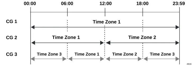
Time Zones
This feature allows the programming of up to three time zones for a given channel group, thus enabling
different min/max scenarios and different services for each channel group.
In the example shown in
Figure 3
, Channel Group 1 is set for one time zone that starts at 00:00 and ends at
23:59.
Channel Group 2 is set for two time zones. Time zone 1 starts at 00:00 and ends at 12:00 hours; time zone
2 starts at 12:00 hours and ends at 23:59 hours.
Channel Group 3 is set for three time zones. Time zone 1 starts at 00:60 hours and ends at 12:00 hours.
Time zone 2 starts at 12:00 hours and ends at 18:00 hours. Time zone 3 starts at 18:00 hours and ends at
00:60 hours.
Figure 3 Time Zones
An example of an application for time zones would be a cable TV provider. During the day, they would
have more outbound trunk lines set up for telemarketing. In the evening, there would be more inbound
traffic as people would be ordering subscriptions services. Therefore some lines would be shared by more
than one trunk group to ensure that all the traffic can be handled. There would also be several lines
reserved for DID calls.
Call-by-Call Programming
There are three programs used to set up the Call-by-Call feature.
Program
*
67-5 – Multiple Time Zone Settings. This program maps the channel groups to the time zones.
Program
*
67-3 – ISDN Trunk Group Minimum Channel Reservation.
This program sets the number
of reserved channels for a given trunk group. These channels will be reserved to a type of service, such as
800 calls, DID, etc. You can specify up to 47 B-channels as a minimum if D-channels are shared using
Non-Facility Associated Signaling.
Note
Available shared channels is the total number of channels in a channel group (23 or 47) minus the
total reserved (minimum) channels assigned to all trunk groups within the channel group.
Program
*
67-4 – ISDN Trunk Groups Maximum Channel Reservation.
This program sets the
maximum number of B-channels for a given trunk group. The maximum number determines the number of
available B-channels available from the total shared channels.
Important!
To allow Strata DK Automatic Callback (ACB) and trunk queuing to function when using
trunk group or LCR access codes to make an outgoing call, the maximum value for a trunk
group (i.e., Tie line group) should not exceed the number of lines ordered from the Central
Office for that facility’s trunk group.
Time Zone 1
12:00 18:00 23:59
06:00 00:00
Time Zone 2 Time Zone 3
Time Zone 3 Time Zone 1
Time Zone 2 Time Zone 1
CG 2 CG 1
CG 3