ISSN: 2319-8753
I
nternational
J
ournal of
I
nnovative
R
esearch in
S
cience,
E
ngineering and
T
echnology
(An ISO 3297: 2007 Certified Organization)
Vol. 2, Issue 9, September 2013
Damage Tolerance Evaluation of the Front Spar
in a transport aircraft wing
Diganth Kumar B N
1, Dr.K.Mahesh Dutt
2PG Student , Department of Mechanical Engineering, KSIT, Bengaluru, Karnataka, India1 Associate Professor, Department of Mechanical Engineering, KSIT, Bengaluru, Karnataka, India2
Abstract:
For the continued airworthiness of an aircraft during its entire economic service life, fatigue and damagetolerance design, analysis, testing and service experience correlation play a pivotal role. In a transport aircraft there are usually two spars to take the bending loads. The main spar takes a major portion of this bending moment. It is the major critical structural elements in a transport wing. Most service structural failures in structures are due to fatigue cracks. Fatigue cracking cannot be avoided but can be tolerated by suitable damage tolerance design.
In large transport wings the main spar is an integrally machined component which gets mechanically fastened to the skin and ribs. The mechanical fastening leads to severe stress concentration at a few fastener holes. Under service loading a fatigue crack can initiate from the most severe stress concentrator. This fatigue crack will grow under service loading first in the flange and then grow into the spar web. This crack growth can lead to catastrophic failure if not detected during service and repaired. This project work will investigate alternate structural design of the main spar to make it damage tolerant. The spar construction here will be having one more intermediate flange and at an assumed height of 1/3rd from the bottom flange of the spar. In the event of fatigue cracking the bottom flange and web may fail but the top flange, web and the intermediate flange will remain intact and can be designed to carry the required design limit load. A finite element modeling and analysis approach will be employed to study both types of spar constriction and validate the damage tolerance design concept.
Keywords: Transport aircraft, Spar, Damage tolerance design, Finite element analysis, Fatigue crack, Service loads
I. INTRODUCTION
The spar is responsible to support bending loads and it is a structural link between wing and fuselage, it is often considered the main structural member of the wing. Its position in the main structure is normal to the flow direction and is extended from the fuselage to the wing tip. Sometimes, it has a certain angle due to the sweep angle of the wing. Normally, the spar has a cantilever shape and there are two spars on the wing. The main spar or front spar is near the leading edge, about 25% of the chord, the other one is smaller and is located near the trailing edge. The main spar carries the lift through the fuselage to the other wing, to resist forward and aft movement. The smaller one is tied to the main spar by the ribs or stressed skin (forming a wing-box structure). This configuration provides some rigidity, needed either in flight or on the ground.
ISSN: 2319-8753
I
nternational
J
ournal of
I
nnovative
R
esearch in
S
cience,
E
ngineering and
T
echnology
(An ISO 3297: 2007 Certified Organization)
Vol. 2, Issue 9, September 2013
II. PROBLEM DEFINITION
A. Objective - "Damage Tolerance Evaluation of the Front Spar in a transport aircraft wing". Here the entire project work is to provide maximum safety to the aircraft wing using Damage Tolerance Design concept. In order to achieve this objective, the general structural configuration of front spar is modified, in general spar mainly consists of flanges at the top and bottom and web in between them i.e., I-section tapered beam like structure, but to achieve our objective using Damage tolerance evaluation concept Spar structural design can be modified by locating intermediate flange parallel to the spar flanges approximately at the 1/3rd height from spar bottom flange, even after design modification it is not possible to avoid the further crack growth in the structure, but crack growth rate can be slowdown for some period of time until the next regular inspection and making the structure damage tolerant. this Damage tolerance design is one of the advanced fatigue design criteria presently implemented in many industries to overcome the drawbacks of past methods and also to provide safety to the vehicle at any worst conditions like unnoticeable catastrophic failure in the inner parts of the structure that results in destruction of entire aircraft & also the loss of life and property.
B. Scope of the Project work
Global and Local analysis has to be carried out for Wing box & Front Spar of the wing respectively, this can be carried out by meshing, applying loads and boundary conditions to the structures, and solving both of them using FEM package so that the analysis results obtained is Numerical solution and further it has to be compared with analytical or theoretical solution calculated through SOM approach in order to validate the solution obtained from both methods. In order to evaluate the damage tolerance for a spar, first verification are to be carried out using popularly used MVCCI technique (Modified Virtual Crack Closure Integral) for a plate with a crack problem, to calculate stress intensity factor. further this numerical approach are to be compared with the theoretical approach, so that the value of SIF(K) in both must be almost same, then only it is possible to apply this technique to solve the problem given, for calculating SIF(K) with different crack lengths.
After verifying the MVCCI technique, at the achieved maximum elemental stress location, in the nearby rivet hole of the front spar bottom flange, crack is assumed for some initial length and further crack length are increased incrementally. propagation of crack carried out for different assumed incremental crack lengths starting from 10mm to the value were SIF(K) reaches fracture toughness(KIC) of the AL-2024- T351 material for given spar configuration. after this a graph of SIF(K) obtained with different crack lengths for a spar will be plotted. Now in order to tolerate crack propagation that is taking place at the faster rate, design modification are to be done for spar by adding intermediate flange at approximately 1/3rd of the height from the bottom flange by considering some of basic technicality so that maximum safety has to be provided to the modified structure. again SIF(K) values will be calculated, for modified spar with different crack lengths starting from 10mm to some value above the KIC value were intermediate flange is located and graph will be plotted for these SIF values v/s crack lengths and both graphs will be compared, and conclusion obtained. After comparing SIF(K) v/s Crack length(a) for Spar with and without intermediate flange, similar comparison will be done even for Residual strength versus Crack length, and graph will be plotted and inference will be drawn, and finally by observing all graphs, it is possible to conclude that with design modification ,the spar structure becomes damage tolerant, thus provide possible safety to the structure and catastrophic failure can be avoided, hence achieving project objective.
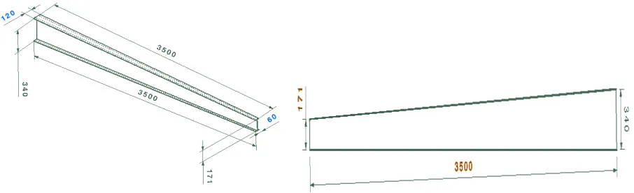
C. Geometrical configuration
Geometry of wing box model isometric view and also the dimensions of top & bottom skin of wing and is as shown in figure1.
ISSN: 2319-8753
I
nternational
J
ournal of
I
nnovative
R
esearch in
S
cience,
E
ngineering and
T
echnology
(An ISO 3297: 2007 Certified Organization)
Vol. 2, Issue 9, September 2013
Figure 1: Isometric wing box model & Dimensions of wing top and bottom skin.
Figure 2: Isometric view of front spar model dimensions & Front Spar web dimensions. D. Material specification
Aluminum 2024-T351 Material Description for Structural Analysis
Aluminum alloy 2024 is an aluminum alloy with copper and magnesium as the alloying elements. It is used in applications requiring high strength to weight ratio, as well as good fatigue resistance. It is not weldable, and has average machinability. Due to its high strength and fatigue resistance, 2024 is widely used in aircraft structures, especially wing and fuselage structures under tension.
Table 1: Mechanical properties of 2024-T351 Table 2: Composition of Aluminum Alloy – 2024-T351 Composition Wt. % Composition Wt. %
Al 90.7-94.7 Mn 0.3-0.9
Cr Max. 0.1 Si Max. 0.5
Cu 3.8-4.9 Ti Max. 0.15
Fe Max. 0.5 Zn Max. 0.25
Mg 5.2-5.8 Others Max. 0.15
Material property Values Modulus of elasticity GPa, E 70.3-72.4 Tensile strength MPa, σu 470
Yield strength MPa, σy 325
Shear strength MPa, ϑs 285
Fatigue limit , MPa,σw 140
ISSN: 2319-8753
I
nternational
J
ournal of
I
nnovative
R
esearch in
S
cience,
E
ngineering and
T
echnology
(An ISO 3297: 2007 Certified Organization)
Vol. 2, Issue 9, September 2013
III. FINITE ELEMENT ANALYSIS
In this project MSC PATRAN software is used as the pre-processor and post processor. The pre-processing task includes building the geometric model by importing it from CATIA solid model of wing box structure and extracting geometry, building the finite element model, giving these elements the correct material properties, setting the loads & boundary conditions and finally, assembling these elements into a connected structure for analysis. Analysis is done in MSC NASTRAN solver . The analysis stage simply solves for the unknown degrees of freedom, as well as reactions and stresses. In the post processing stage, the results are evaluated and displayed.
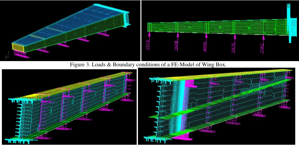
A. Loads and Boundary Conditions
Applying loads & boundary conditions to the structures becomes very important for getting deformation and stresses, for obtained FE-Model of wing box and also for spar without & with intermediate flange. Here, all six degrees of freedom (3 translation & 3 rotations) are constrained at the fixed end of the wing box, & loads calculated at 5 different stations of the wing box and front spar are applied. depending upon the given structural configuration required calculated loads at 5 different rib stations are uniformly distributed equally throughout the web & flanges of the spar structure so that total load is equal to distributed load. & it is as shown in the figures below
.
Figure 3. Loads & Boundary conditions of a FE-Model of Wing Box.
Figure 4. Loads & Boundary conditions of a FE-Model of a Spar without and with intermediate flange
B. Analysis of structures
ISSN: 2319-8753
I
nternational
J
ournal of
I
nnovative
R
esearch in
S
cience,
E
ngineering and
T
echnology
(An ISO 3297: 2007 Certified Organization)
Vol. 2, Issue 9, September 2013
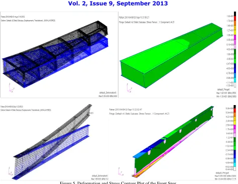
Figure 5. Deformation and Stress Contour Plot of the Front Spar
IV. DAMAGE TOLERANCE EVALUATION APPROACH A. SIF Calculations
After verification of FEM Approach for Stress Intensity Factor (SIF) Calculation by MVCCI method with classical approach whether the method is possible to apply for a spar with crack or not. it is observed that same approach can be applied to the spar structure to calculate SIF(K) with different crack lengths. first it is applied for spar without intermediate flange then it is applied for a modified spar with intermediate flange, finally both of them will be compared and validated to make the spar damage tolerant, finally graph will be plotted for calculated K values to study the behavior of both the structures.
B. SIF calculation of Front Spar Without & With Intermediate Flange using MVCCI Method SIF calculation For Crack length of 10mm
X
F
X a tX
v
2
ISSN: 2319-8753
I
nternational
J
ournal of
I
nnovative
R
esearch in
S
cience,
E
ngineering and
T
echnology
(An ISO 3297: 2007 Certified Organization)
Vol. 2, Issue 9, September 2013
Similarly SIF(K) calculations are carried out for different crack lengths like 20 , 30 40, 50, 60, 70, 80, 90, 100, 110 & 120 mm and so on until K ≥ KICcondition achieved for spar without and with intermediate flange. comparison K values for
incremental crack lengths for a spar without & with intermediate flange are tabulated as shown in the below table 3. and also Plot of Variation of SIF(K) as a Function of Crack length(a) for a spar without and with Intermediate Flange graph is plotted as shown in the figure 6.
C. Residual Strength Calculations as a function of Damage size for the Spar with & without intermediate flange. Residual Strength Calculations for crack length of 10 mm,
MRes10 = K IC10 K10
x MApplied
10 =
72.37
50.26
x 794034.943 = 1143340.804 Kg-mm
Similarly Residual Strength calculations carried out for different incremental crack lengths like 20 , 30 40, 50, 60, 70, 80, 90, 100, 110 & 120 mm for spar without & with intermediate flange. comparison residual bending moment values for different incremental crack lengths for both spar without & with intermediate flange as been tabulated as shown in the below table 4. Plot of comparison of Residual Strength(Rs) as a Function of Damage Size for spar with and without Intermediate Flange graph is plotted as shown in the figure 6.
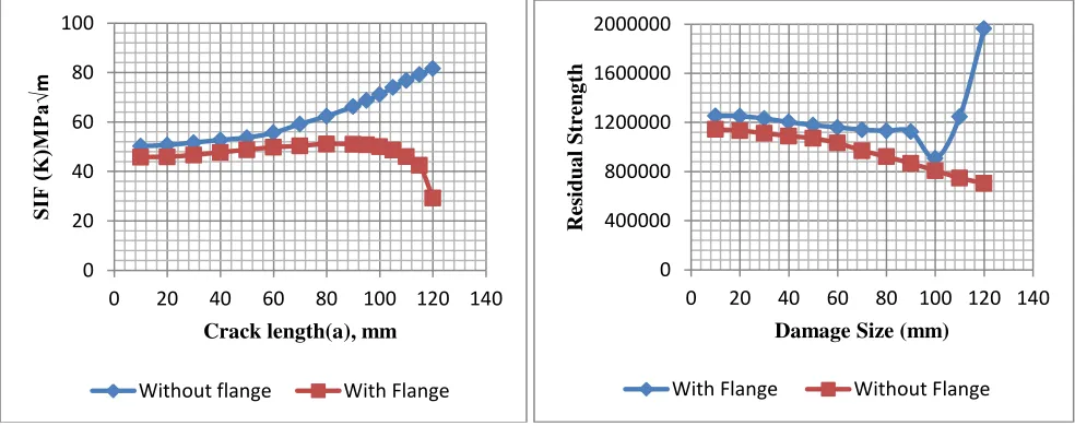
Figure 6. Comparison of SIF (K) v/s Crack length (a) & Residual Strength v/s Damage Size for Front Spar structure with & without Intermediate Flange.
V. RESULTS AND DISCUSSION
After Meshing, assigning material property and applying loads and boundary conditions to both global analysis model wing box & local analysis model front spar and solving both through NASTRAN and again plotting results in PATRAN, for wing box the Max deformation value observed is 6.38 mm & Max stress value observed 19.2Kg/mm2. so after getting these results, global analysis will be completed, and smilarly for front spar the Max deformation value observed is 16.6 mm around free end of spar & Max stress value observed is 5.86Kg/mm2 around the fixed end of spar. thus after getting these results, local analysis also completed.
0 20 40 60 80 100 120 140 0 20 40 60 80 100
Crack length(a), mm
SI F (K )M Pa √ m
Without flange With Flange
0 400000 800000 1200000 1600000 2000000
0 20 40 60 80 100 120 140
Resid ua l Str eng th
Damage Size (mm)
ISSN: 2319-8753
I
nternational
J
ournal of
I
nnovative
R
esearch in
S
cience,
E
ngineering and
T
echnology
(An ISO 3297: 2007 Certified Organization)
Vol. 2, Issue 9, September 2013
Now comparing the results of both the global and local analysis, it is observed that max stress value of global analysis is 19.2 Kg/mm2 is more than the max stress value of 5.86 Kg/mm2 obtained from local analysis , but it is important to observe that deformation value of 16.6mm of local analysis is more than the deformation value of 6.38 mm of global analysis, so this clearly says that in a wing box structure, spar structure undergoes Max deformation than any other parts of the wing box, so with this conclusion it is clear that results obtained not violating the basic structural analysis criteria of a wing, further the problem can be continued to achieve the objective
MVCCI Method (Modified Virtual Crack Closure Integral) for stress intensity factor calculation, this numerical approach carried out using a rectangular plate with a center crack problem, and after solving SIF(K) value of 4.431 Mpa√m is obtained, and is compared with the SIF(K) value of 4.36 Mpa√m, obtained from classical approach, the SIF(K) values obtained from both approaches is almost same, thus further this technique used to solve the spar with crack problem, for calculating SIF(K) values with different crack lengths, for both spar without & with flange.
After this a graph of SIF(K) obtained with different crack lengths are to be plotted as shown in the figure 4, from figure.4, it is observed that SIF(K) values goes on increasing with increasing crack length, stress intensity factor value of 76.82 MPa√m was observed at crack length of 110 mm, this value crosses the KIC value of the material and finally if this increase in crack length continues then it leads to a catastrophic failure of the structure.
Further to avoid catastrophic failure of the structure, Design modification is carried out for spar by adding intermediate flange, and again for this modified spar SIF(K), as a function of crack length starting from 10mm to 120 mm, graph was plotted as shown in figure 4, & further compared with that obtained before modification. from figure 4 it is observed that after introducing intermediate flange, it is observed at crack length of 80 mm itself the maximum value of SIF(K) value 51.161MPa√m is obtained, but this obtained max value is much less thanthat obtained before modification and finally at higher crack length of 120 mm where intermediate flange was located, there is a drastic decrease in the SIF(K) value to 29.259 MPa√m .This SIF value is much less than the fracture toughness value(72.37 MPa√m) of given AL2024 T351 material. thus using intermediate flange, crack propagation in the spar was reduced drastically as shown in the figure 4.
Similar comparison carried out for Residual strength as a function of damage size, by calculating Residual strength for spar with and without intermediate flange from 10 mm to 120 mm as shown in figure 4. for spar without flange at crack length of 10 mm, the maximum value of Residual moment observed was 1143340.804 Kg-mm, and this value goes on decreasing as crack length start increasing, and finally at crack length of 120 mm it decreases to 703654.650 Kg-mm, this indicates that without intermediate flange structure decreases its residual strength and finally at some higher crack length, catastrophic failure of the structure may take place. but after introducing intermediate flange Residual moment value increases from 1143340.804 Kg-mm to 1253037.698 Kg-mm at crack length of 10 mm, & finally at 120mm there is a higher increase in value from 703654.650 Kg-mm to 1963987.45 Kg-mm, so this increase in residual strength for higher crack length concludes that spar structure is strengthened by introducing intermediate flange. from this it is concluded that, the intermediate flange here used acts as a crack arrester to arrest the fast fracturing crack much effectively by drastically slowing down the crack growth at this location as shown in the figure 4. hence damage can be tolerated for some time in the structure, and thus maximum safety is provided to the spar after modification and thus avoiding the future catastrophic failure of the structure.
VI. CONCLUSION
Comparing global and local analysis for wing box and spar, it was observed that in both analysis stresses & deformation obtained are comparable and acceptable thus this gives the benchmark for further analysis, and also max elemental stresses was observed at the spar bottom flange thus spar becomes most critical part in the wing box for continuation of work on spar structure to achieve project objective.
ISSN: 2319-8753
I
nternational
J
ournal of
I
nnovative
R
esearch in
S
cience,
E
ngineering and
T
echnology
(An ISO 3297: 2007 Certified Organization)
Vol. 2, Issue 9, September 2013
Comparing graphs plotted for both SIF(K) & Residual strength as a function of crack length for both spar structure without and with intermediate flange, from both comparison it can be concluded, that before introduction of intermediate flange the spar structure was leading to catastrophic failure due to fast rate crack propagation. but after introduction of intermediate flange to same spar structure, further crack propagation slows down drastically, thus makes the structure damage tolerant, hence provides safety to the structure for some time by avoiding catastrophic failure of the structure as that was occurring before design modification. hence achieving objective of the project.
ACKNOWLEDGMENT
I express my sincere gratitude to all the engineers in BAIL especially to Mr. K.E Girish, Director, BAIL and Dr P K Dash, Chairman, BAIL Bengaluru for their support and guidance, motivation and valuable advice to carrying out the study in a successful manner. I stand grateful to my internal guide Dr K Mahesh Dutt, for his guidance, patience & support that he had given me throughout the work.
REFERENCES
[1]Jaap Schijve, “Fatigue damage in aircraft structures, not wanted, but tolerated” Delft University of Technology, Faculty of Aerospace Engineering Kluyverweg 1, 2629 HS, the Netherlands.
[2]Ulf G. Goranson " Damage Tolerance Facts and Fiction" International Conference on Damage Tolerance of Aircraft Structures 25th September,2007
Delft Technical University Delft, The Netherlands.
[3]Ericj.Whitney, Kim White " Fatigue and damage tolerance evaluation of cessna 210 wing carry through structure" AEA aerospace group. Aircraft airworthiness and sustainment conference – brisbane – 2010.
[4]Grandt, Jr. Raisbeck "Damage tolerant design and nondestructive inspection -keys to aircraft airworthiness" The 2nd international symposium on aircraft airworthiness (Isaa 2011)
[5]Venkatesha B K, Suresh B S, Girish K E " Analytical Evaluation of Fatigue Crack Arrest Capability in Fuselage of Large Transport Aircraft", ISSN (Print): 2319-3182, Volume-1, Issue-1, 2012.
[6]A. Ramesh Kumar1, S. R. Balakrishnan2, S. Balaji3" Design Of An Aircraft Wing Structure For Static Analysis And Fatigue Life Prediction" International Journal of Engineering Research & Technology (IJERT) Vol. 2 Issue 5, May - 2013.
[7] David Broek, “Elementary Engineering Fracture Mechanics” ,Martinus Nijhoff Publishers, pp. 115-119, 317-338, 408-415 III Edition, 1984. [8] Ralph I Stephens, Ali Fatemi, Robert R. Stephens, Henry O Fuchs “ Metal Fatigue in Engineering”, John wiley Newyork , pp.23-27, 123-126, II Edition, 2001.
[9]Tirupathi R. Chandrupatla, Ashok D. Belegundu, " Introduction to Finite Elements in Engineering", pp.412-425, Eastern Economy 2nd Edition. [10]R. K Rajput "Strength of Materials" S. Chand & Company Ltd publications, pp.261-275, 4th Edition, 2009.