ISSN 2348 – 7968
An Over Surface Air Distribution: A Numerical Validation
TusharPokharkarP 1
P
and KunalbhavsarP 2
P
1
P
Student, Mumbai University/SPCE, Andheri, Maharashtra, India
P
2
P
Mechanical Department, Mumbai University/SPCE, Andheri, Maharashtra, India
Abstract
In this paper, the effects of separate location of return and exhaust grilles on thermal comfort and energy saving is studied for Over Surface Air Distribution (OSAD). With varying return grille height numerical investigation is carried out for room on Fluent 14.1. Decreasing the height of return grille increases exhaust air temperature and decreases the return air temperature, ultimately reducing the cooling coil load.
Keywords: OSAD, UFAD26T, STRAD, CFD, HVAC, IAQ
1. Introduction
The most critical factor faced in our work space is flexibility to adapt to changes which are driven by technological evolution, and accordingly design our workspaces to forestall obsolescence. In fact, the greatest challenge today in space management is to make work spaces aesthetic, efficient and flexible or in short, to make them ergonomic
As maintaining a higher level of indoor air quality (IAQ) becomes increasingly important to today’s business owners and their employees, engineers are challenged to improve HVAC design. Designing to provide comfort and better IAQ with traditional air distribution systems consumes high amounts of energy and therefore, results in high operational costs. The challenge of HVAC engineers face is to provide comfort while reducing energy consumption and the operating expenses that accompany it. In response to new regulations and rising energy costs, the HVAC industry is changing at a rapid pace, providing today’s engineers with new tools to meet this challenge. Under floor air distribution (UFAD) systems are shown to offer potential for initial capital savings, which may be achieved by lowering slab-to-slab heights, reducing cooling capacity requirements due to stratification, thermal inertia improvements, minimizing ducting, and reducing construction schedules. UFAD systems are also shown to provide significant energy efficiency advantages due to fan energy savings, extended free cooling and improved chillier COP, thereby reducing life-cycle building costs. Additionally, improvements in occupant thermal comfort and IAQ are achieved. Unlike displacement systems,
UFAD systems extend these high levels of IAQ to applications with significant movement and/or heating. According to F. Bauman and A. Daly[1], Stratified air distribution (STRAD) systems have been studied intensively over the past two decades, in view of its potential better performance than conventional mixing ventilation (MV) systems. R.L. Gorton, H.M. Bagheri [2].State that in a STRAD system, the conditioned air is delivered directly to the occupied zone and flows upward due to thermal plumes generated from heat sources. The thermal buoyancy from occupants induces the fresh air from the lower part of space to the breathing level and makes a much better inhaled air quality for occupants. In addition, since only the occupied zone of a space needs to be cooled, it inherently has potentials to save energy. Xu and Niu[3] concluded that the energy saving for an under floor air distribution (UFAD) system was derived from three factors: an extended free cooling period, a reduced ventilation load and increased coefficients of performance (COP) for chillier. Local draft discomfort and too large temperature gradient in the occupied zone are two main thermal comfort problems that are frequently associated with STRAD systems. However, studies also testified that a thermally comfortable environment can be maintained in a well-designed STRAD.
Previous researches have demonstrated that the locations of exhaust inlet can strongly affect the performance of a STRAD system. But in most of previous studies, the return and exhaust inlets are combined together as shown in Fig. 1(A) and (B). Recently, Xu[4] pointed out that STRAD systems with separated locations of return and exhaust grilles, as presented in Fig. 1(C) and (D), may provide further extra energy saving potentials. The cooling coil load calculation in a STRAD system is different with that in a MV system for the same room set-point air temperature (
𝑡
𝑠𝑒𝑡) (◦C)𝑄𝑐𝑜𝑖𝑙−𝑀𝑉 = 𝑄𝑆𝑝𝑎𝑐𝑒 + 𝑄𝑉𝑒𝑛𝑡 (1)
𝑄𝑐𝑜𝑖𝑙−𝑆𝑇𝐴𝑅𝐷=𝑄𝑐𝑜𝑖𝑙−𝑀𝑉- 𝐶𝑝𝑚𝑒(𝑡𝑒 -𝑡𝑠𝑒𝑡) (2) where
𝑄
𝑐𝑜𝑖𝑙−𝑀𝑉 and𝑄
𝑐𝑜𝑖𝑙−𝑆𝑇𝐴𝑅𝐷the cooling coil load for MV system and STRAD system, respectively;𝑄
𝑆𝑝𝑎𝑐𝑒exhaust air flow rate and
𝑡
𝑒 (◦C) is the exhaust air temperature. From comparing equation 1 and 2 it is obvious that the item𝐶
𝑝𝑚
𝑒(
𝑡
𝑒-
𝑡
𝑠𝑒𝑡)
is the reduced cooling coil load in a STRAD system and named as ∆𝑄
𝑐𝑜𝑖𝑙 (W). STRAD with exhaust air at ceiling level and return air at occupied zone make it possible to impel much more convective heat, especially those generated at the upper zone, from exhaust inlet directly.2. Problem Definition
Generally, in OHAD the air is supplied at 55° F (12.8°C). The system’s return air is also at ceiling level. Since the supply and return air are at the ceiling, the supply air mixes with the space contaminants before reaching the occupied zone, diluting space contaminants to improve the indoor environment. There are some disadvantages with OHAD, energy cost is higher and indoor air quality is also not good. In OHAD without raised floor, cable management and space modification will be expensive.
Under floor air distribution systems typically supply air at discharge temperatures between (14°C to 17°C) utilizing special high induction floor diffusers. This is particularly important as supply air is being introduced within the occupied regions of the space, so it is necessary that discharge velocities and temperatures are optimum. There are some disadvantages with UFAD like plenum must be tightly sealed to minimize leakage and some under floor duct distribution may require. Supply air jets leaving the outlets create mixed air flow conditions in the lower regions of space; however, their mixing effect depends on the discharge velocity of air stream.
So, to overcome the disadvantages of OHAD and UFAD, concept of OSAD arises. Experimental study has been done on OSAD but very few numerical studies has been done on OSAD.
3
.Methodology
3.1.
Physical / Geometry Modeling
Experimental set up of Yuanda Cheng, JianleiNiu [5] is considered for the numerical study of OSAD which can be seen in Fig. 4.
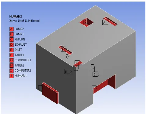
Physical modelling of room was done with the help of ANSYS Workbench- Design Module as shown in Fig. 1. It consists of inlet, return, exhaust, two lamps, two computers, two humans. In this the height of return grill is varying from 2.05m to 1.65m. Table 1 gives the heat sources considered and their heat loads.
Figure 1: Geometric Modelling from mathematical modelling.
Figure 2: Ventilation system of the climate chamber. 1-Chiller, 2-supply fan,3-highefficiency filter, 4-heat exchanger, 5-butterfly valve, 6-flow equalizing plate, 7-supply air inlet, 8-return air inlet, 9-exhaust air inlet, and 10-exhaust fan.
Figure 3: Indoor air temperature measurements (a) measuring positions
Figure 4: (a) The arrangements in the climate chamber and (b) reality image for the inside of climate Chamber [5].
Table 1: The dimension of the diffusers and the heat loads in the climate
chamber.
Diffusers Dimensio n (m)
Heat Sources
Heat Load (W) Supply Outlet 1 x 0.6 Computer 125 W x 2
Return Inlet 0.5 x 0.5 Manikin 80 W x 2
Exhaust Inlet 0.45 x 0.2 Lamp 48 W x 2
3.2. Mathematical Modeling
The flow inside the shell is approximated as 3dimensional, steady state, with adiabatic walls. Standard k-e model is used for turbulence modeling. Following equation govern the flow inside the room:
Governing Equations
Equation 3 Mass Balance, 𝜕𝑢
𝜕𝑥
+
𝜕𝑣 𝜕𝑦+
𝜕𝑤 𝜕𝑧=0 Equation 4
X - Momentum Equation
𝜌 �𝑢𝜕𝑢𝜕𝑥+𝑣𝜕𝑢𝜕𝑦+𝑤𝜕𝑢𝜕𝑧 � = - 𝜕𝑝 𝜕𝑥 + 𝜇(
𝜕2𝑢
𝜕𝑥2 +
𝜕2𝑢
𝜕𝑦2 +
𝜕2𝑢
𝜕𝑧2 )
Equation 5
Y - Momentum Equation
𝜌 �𝑢𝜕𝑣𝜕𝑥+𝑣𝜕𝑣𝜕𝑦+𝑤𝜕𝑣𝜕𝑧 �= - 𝜕𝑝
𝜕𝑦 + 𝜇( 𝜕2𝑣 𝜕𝑥2 + 𝜕
2𝑣
𝜕𝑦2 + 𝜕 2𝑣
𝜕𝑧2 )
Equation 6
Z - Momentum Equation
𝜌 �𝑢𝜕𝑤𝜕𝑥+𝑣𝜕𝑤𝜕𝑦+𝑤𝜕𝑤𝜕𝑧 �= - 𝜕𝑝
𝜕𝑧 + 𝜇( 𝜕2𝑤
𝜕𝑥2 +
𝜕2𝑤
𝜕𝑦2 +
𝜕2𝑤
𝜕𝑧2 )
Equation 7
Energy Equation
𝜌𝑐𝑝 [𝑢𝜕𝑇𝜕𝑥+𝑣𝜕𝑇𝜕𝑌+𝑤𝜕𝑇𝜕𝑍 ] = k[𝜕
2𝑇
𝜕𝑥2 + 𝜕 2𝑇
𝜕𝑦2+ 𝜕 2𝑇
𝜕𝑧2 ] + 𝜇∅+ q
Where,
𝜇∅= 𝜇{( 𝜕𝑢𝜕𝑦+𝜕𝑣𝜕𝑥+𝜕𝑤𝜕𝑥 )2 + 2[( 𝜕𝑢 𝜕𝑥)2 +(
𝜕𝑣 𝜕𝑦)2 +(
𝜕𝑤 𝜕𝑧)2] }
Equation 8
Ideal Gas Law P = 𝜌𝑅𝑇
3.3. Meshing
Numerical simulation of the cases presented is done through the ANSYS Fluent 14.5. It starts with the selection and modeling of the computational domain and its meshing. Meshing was done on physical model by Meshing Module of ANSYS Workbench. Unstructured type of mesh was used. Figure 5 shows the meshing for room. Mesh is having minimum quality as 2.4969 X10⁻¹ and maximum aspect ratio as 1.6155 X101.
Figure 5: Mesh Room use for analysis when return grill is at 2.05m.
Table 2: Solution Methods use for Simulation
Scheme SIMPLE
Gradient Least Square Cell Based
Pressure PRESTO!
Momentum Second Order Upwind
Turbulent Kinetic Energy First Order
Turbulent Dissipation Rate First Order
Table 3: Boundary and Initial Condition
Surface Type of
Boundary
Details
Inlet Velocity inlet 0.14 m/s & 292 K
Exhaust Pressure Outlet 0 gauge
Return Pressure Outlet 0 gauge
Room Walls
Wall Adiabatic wall condition
Initial condition
Temperature 297 K
SIMPLE scheme with second order upwind momentum equation were applied.
4. Results and Discussion
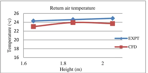
Experimental results [5] are shown in Table 4. Validation of current numerical results with the experimental results [5] is shown in Fig. 5 & Fig 6, which clearly shows that both results are very close, capturing physics correctly. Fig. 5 shows that with increasing grille height from 2.05 m to 1.65 m the return air temperature increases whereas the exhaust temperature decreases.
Table 4: Energy saving for cooling coil [5]
Figure 5: Validation graph for Height vs Return air Temperature (P
o
P
C)
Figure 6: Validation graph for Height vs Exhaust air Temperature (P
o
P
C)
Figure 7: Validation graph for Height vs Efficiency of coil (%) 16
18 20 22 24 26
1.6 1.8 2
T
em
p
er
at
u
re (
◦c)
Height (m) Return air temperature
EXPT CFD
24.5 25 25.5 26 26.5
1.5 1.7 1.9 2.1 2.3
T
em
p
er
at
u
re (
◦c)
Height (m)
Exhaust air temperature
EXPT.
CFD
79 89 99 109
1.6 1.8 2
Δ
Q (
%
)
Height (m)
Efficiency of coil
EXPT
CFD
Height of return
grill (m) 𝑡℃1.1𝑏
Return
air
temperature (℃)
Exhaust
Air
temperature (℃)
∆𝑄𝑐𝑜𝑖𝑙
( W)
∆𝑄𝑐𝑜𝑖𝑙/𝑄𝑠𝑝𝑎𝑐𝑒 ( %)
Expt Expt Expt Expt Expt
Case 1 2.05 24.3 24.9 25.4 82.8 16.4
Case 2 1.85 24.2 24.6 25.7 100.6 19.9
As height of return grill decreases exhaust temperature increases due to which there is an increase in ∆𝑄𝑐𝑜𝑖𝑙 and energy saving for cooling coil also increases. Figure 7 shows the same effect on decreasing return grille height.
Table 4[5] illustrates the influence of the height of return grill location of cooling load, which is calculated using equation 2. As the return inlet is lowered, the exhaust air temperature is increased thus the energy saving for cooling was significantly increase from 16.4% to 21%. The numerical results match with experimental results [5] with maximum of 5% of an error.
5. CONCLUSION
Thermal comfort of occupants and energy saving for cooling coil in air distribution systems with separated locations of return and exhaust inlets were the main concerns of this study, with the reference of experimental data simulations were conducted. The results demonstrated that keeping the exhaust inlet at ceiling level and locating the return inlet at middle level provided potentials to achieve energy saving. As the return inlet position decreased from ceiling level to the lower zone while keeping the exhaust at ceiling level, the energy saving for the cooling coil increases up to 21%.
References
[1] F. Bauman, A. Daly, Under floor Air Distribution (UFAD) Design Guide, ASHRAE, Atlant, GA, 2003
[2] R.L. Gorton, H.M. Bagheri, Verification of stratified air condition design, in ASHRAE report 388-RP, ASHRAE, 1986. [3] H.T. Xu, J.L. Niu, Numerical procedure for predicting annual energy consumption of the under floor air distribution system, Energy and Buildings 38 (2006)641–647.
![Figure 4: (a) The arrangements in the climate chamber and (b) reality image for the inside of climate Chamber [5]](https://thumb-us.123doks.com/thumbv2/123dok_us/7821301.1295926/3.612.314.547.347.544/figure-arrangements-climate-chamber-reality-inside-climate-chamber.webp)