1 | P a g e
A CASE STUDY FOR HARMONIC PRESENCE
INVESTIGATION AND MITIGATION IN A CNC
MACHINE PLANT
Devesh Singh Tomar
1, S.C. Gupta
2,
1
Department of Electrical Engineering, Sunrise University, Alwar, (India)
2
Director, RKGIT, Ghaziabad, (India)
ABSTRACT
In this paper analysis of two different cases is being compared for the presence of harmonics at manufacturing
plant. Case 1, is a normal system configuration duly interfaced with CNC, AC servo drives, Spindle drive along
with adaptive and in-process gauging system, High voltage Module, Isolation transformer and switchgear items
and in case 2 additionally part compensated filter is added to reduce both system THvD and THiD levels.
Simulation results proved that the proposed harmonic mitigation method is limiting the harmonic level at all
three locations satisfactorily within 5% as mentioned in IEEE 519 Standard.
Keywords: Harmonic Mitigation, Harmonic Filter, CNC System.
I INTRODUCTION
Harmonic distortion of the voltage and current in an industrial facility is caused by the operation of nonlinear
loads and devices on the power system. A nonlinear load is one that does not draw sinusoidal current when a
sinusoidal voltage is applied. High harmonic currents can have several negative effects on a facility.
High levels of distortion can lower power factors, overheat equipment, and lead to penalties from the
local utility for exceeding recommended limits. Each of these effects can result in higher cost to the
facility.
Harmonic currents increase the volt-amperes required for a load without increasing the watts.
ANSI/IEEE Standard C57 series states that a transformer can only be expected to carry its rated current
if the current distortion is less than 5 The overheating is caused primarily by the higher eddy-current
losses inside the transformer than were anticipated by the designer. The overheating can be avoided by
either de-rating the transformer.
Another effect of harmonic currents, is the overheating of neutral wires in wye-connected circuits. This
effect occurs because the third harmonic (180-Hz) and any multiples thereof do not cancel in the
neutral as do the other harmonic currents.
This potential for overheating can be addressed by over-sizing neutral conductors or reducing
By using a combination of a pre-stored database and new interpolation techniques the software can very fast
provide the harmonic data on real applications. The harmonic results obtained with this software have
acceptable precision even with limited input data. The evaluation concludes here that this approach is very
practical compared to other advanced harmonic analysis methods. The results are supported by comparisons of
calculations and measurements given in a publication “Power Electronics and Applications, 2005 European Conference”.
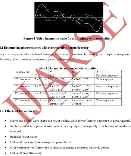
Figure 1 Third harmonic wave forms in phase with each other
1.1 Determining phase sequence with corresponding harmonic order
Negative sequence odd numbered harmonics are more distructive for heating and torque development.The
following table 1 provides the sequence pattern of harmonics:
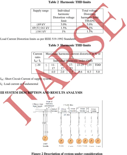
Table 1 Harmonic Sequence determination
Fundamental R
0˚ Y 120˚ B 240˚ A-B-C Positive sequence
3rd Harmonic
00
Zero sequence
5th Harmonic
720: (-)120 1440: (-) 2400
Negative sequence
7th Harmonic
720: (+) 120 1440:(+) 2400
Positive sequence
9th Harmonic
1080: (+)00 2160: 00
Zero sequence
1.2
Effects of harmonics
Harmonics affects wave shape and power quality; while power factor is a measure of power quantity.
Neutral current in 3 phase 4 wire system, is very high,; consequently over heating of conductor, is
observed.
Reduced Power factor
Failure of capacitor banks to improve power factor.
Over heating of transformer due to circulating negative sequence harmonic current.
Failure of protective relay
3 | P a g e
Nuisance tripping of devices
Incorrect Meter functioning (Reading mistakes).
II HARMONICS VOLTAGE DISTORTION LIMITS AS PER IEEE 510-1992 STANDARDS
The THVD and THiD limits are given in following tables 2 and 3.
Table 2 Harmonic THD limits
Supply range Individual
harmonic Distortion voltage
limit
Total voltage Distortion harmonic limit
THvD%
≤69 kV 3.0% 5.0%
69≤V≥161 kV 1.5% 2.5%
≥161 kV 1% 1.5%
Load Current Distortion limits as per IEEE 519-1992 Standards
Table 3 Harmonic THD limits
Current ratio ISC/ IL
Maximum harmonic current distortion in % of IL
Individual Harmonic order (Odd)
≤ 20 ≤
11-17
11-17
17-23
23-25 ≥35 TDD
4.0 2.0 1.5 0.6 0.3 5.0
ISC: Short Circuit Current of supply system
IL: Load current at Fundamental
III SYSTEM DESCRIPTION AND RESULTS ANALYSIS
Even harmonics are limited to 25% of odd harmonic limit.Comparison of Performance Data and Harmonics
Level Before (case 1) and after (case 2) harmonic Mitigation: In our study, two cases are being compared. Case
1, is a normal system configuration duly interfaced with CNC, AC servo drives, Spindle drive along with
adaptive and in-process gauging system, High voltage Module, Isolation transformer and switchgear items.
In case 2 additionally part compensated filter is added to reduce both system THvD and THiD levels. The
comparison is given table 4 below: and associated data
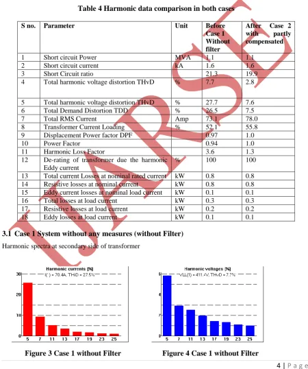
Table 4 Harmonic data comparison in both cases
S no. Parameter Unit Before Case 1 Without filter
After Case 2 with partly compensated
1 Short circuit Power MVA 1.1 1.1
2 Short circuit current kA 1.6 1.6
3 Short Circuit ratio 21.3 19.9
4 Total harmonic voltage distortion THvD % 7.7 2.8
5 Total harmonic voltage distortion THvD % 27.7 7.6
6 Total Demand Distortion TDD % 26.5 7.5
7 Total RMS Current Amp 73.1 78.0
8 Transformer Current Loading % 52.1 55.8
9 Displacement Power factor DPF 0.97 1.0
10 Power Factor 0.94 1.0
11 Harmonic Loss Factor 3.6 1.3
12 De-rating of transformer due the harmonic
Eddy current
% 100 100
13 Total current Losses at nominal rated current kW 0.8 0.8
14 Resistive losses at nominal current kW 0.8 0.8
15 Eddy current losses at nominal load current kW 0.1 0.1
16 Total losses at load current kW 0.3 0.3
17 Resistive losses at load current kW 0.2 0.2
18 Eddy losses at load current kW 0.1 0.1
3.1
Case 1 System without any measures (without Filter)
Harmonic spectra at secondary side of transformer
5 | P a g e
From graph in figure 3 and 4 above, it is illustrated that total current distortion level is 27.5% with dominant
impact of Harmonic order 5,7 and 11. It needs mitigation from clean power quality view point so as to ensure
the compatibility of input power to all electronically sensitive equipment. Apart from reducing thermal effect,
the accuracy and malfunction must be avoided; by eliminating or at least bringing down to acceptable limits as
defined in table 3 and 4 above.
3.2
Case 2 after partly compensation using Filter
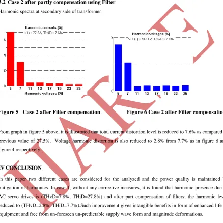
Harmonic spectra at secondary side of transformer
Figure 5 Case 2 after Filter compensation Figure 6 Case 2 after Filter compensation
From graph in figure 5 above, it is illustrated that total current distortion level is reduced to 7.6% as compared to
previous value of 27.5%. Voltage harmonic distortion is also reduced to 2.8% from 7.7% as in figure 6 and
figure 4 respectively.
IV CONCLUSION
In this paper two different cases are considered for the analyzed and the power quality is maintained by
mitigation of harmonics. In case 1, without any corrective measures, it is found that harmonic presence due to
AC servo drives is (THvD=7.8%, THiD=27.8%) and after part compensation of filters; the harmonic level
reduced to (THvD=2.8%, THiD=7.7%).Such improvement gives intangible benefits in form of enhanced life of
equipment and free from un-foreseen un-predictable supply wave form and magnitude deformations.
REFERENCES
[1] IEEE Recommended Practices and Requirements For Harmonic Control in Electrical Power Systems, IEEE
[2] James Will Gray and Frank J. Haddock, “Industrial power quality considerations installing Adjustable
Speed Drive Systems”, IEEE Transactions on Industry Applications, Vol. 32, no. 3, pp. 646-652, May/June
1996.
[3] Allen G Mornec, “Power Quality Considerations for CNC Machines”, Paper ICPSD 00– 16, presented at
the 2000 IEEE/IAS Industrial and Commercial Power Systems Technical Conference.
[4] James Will Gray and Frank J. Haydock, “Industrial power quality considerations installing Adjustable
Speed Drive Systems”, IEEE Transactions on Industry Applications, Vol. 32, no. 3, pp. 646-652, May/June
1996.
[5] H. Lee and R. H. Lee, “Origin & characteristics of harmonic currents- Part l,” Power Quality, pp. 349-351,
1990.
[6] J. A. Oliver and B. B. Banerjee, “Power measurement and harmonic analysis of large adjustable speed
drives,” IEEE Trans. Energy Conversion, vol. 3, no. 2, pp. 384-390, June 1988.
[7] R. P. Stratford, “Harmonic pollution on power systems-A change in philosophy,” IEEE Transaction on
Industrial Application, Vol. IA-16, no. 5, pp. 617-623.Oct. 1980.
[8] D. A. Gonzalez and J. C. McCall, “Design of filters to reduce harmonic Distortion in industrial power
systems,” IEEE Transaction Industrial Application., Vol. IA-23, no. 3, pp. 504-511, June 1987.
[9] A. L. Day and A. A. Mahmoud, “Methods of evaluation of harmonic levels in industrial plant distribution
system” IEEE Transaction on Industrial Application, Vol. IA-23,No. 3, pp. 498-503.2, Dec. 1987.
[10]R. P. Stratford, “Harmonic pollution on power systems-A change in philosophy,” IEEE Transaction
Industrial Application, Vol. IA-16, no. 5, pp. 617-623, Oct. 1980.
[11]F A. De Winter and L. G. Grainger, “A practical approach to solving large drive harmonic problems at the
design stage,” IEEE Transaction on Industrial Application, Vol. 26, Sept./Oct. 1990.
[12]Jingjiang wang, young-june shin, dougal, R.A., “Efficient Harmonic Filter Allocation in an Industrial
Distribution System”, IEEE Transactions on Industrial Electronics, Volume:59 , Issue: 2, pp. 740 – 751.
[13]Badrzadeh, B., Gupta, M., “Practical Experiences and Mitigation Methods of Harmonics in Wind Power
Plants Industry Applications”, IEEE Transactions on Industry Application, Volume 49, Issue 5, pp. 2279 –