Lecture 8
•Traveling Electromagnetic Waves
•Using Ampere’s Law and Faraday’s
Law to derive the EM Wave Equation
•Solution to the Wave Equation
•Wave velocity “v
p”
•Intrinsic impedance of medium “η”
•Waves in Lossy (Conductive) Media
Electromagnetic Wave
• If a sinusoidal current i(t) is set up in a vertical wire (antenna), Ampere’s Circuital Law predicts that a circular time-varying H field lines will be set up (horizontally) around the wire.
• Faraday’s Law predicts that circulating time-varying E field lines will be set up (vertically linking) around these varying H field lines
• Ampere’s Circuital Law predicts that circulating H field lines will be set up horizontally around these varying E field lines, etc.
• A propagating electromagnetic wave results with H oriented horizontally (H = Hyiy) and E oriented vertically (E = Exix)
sin(ωt)
+
-i(t)
H
E E E
H H
x
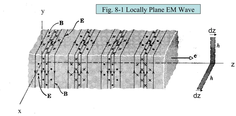
If the observer is far enough away from the wire antenna, the cylindrical wave front becomes “locally plane”. A “snapshot” of the sinusoidal traveling wave that results, with B oriented horizontally along y direction, E oriented along the x direction, and the wave traveling in the z direction, is shown below:
x
z dz
dz
This is called a “uniform plane wave” since Hy and Ex depend only on z and t and NOT on x or y. Thus there is no field variation in the z = constant plane.
Fig. 8-1 Locally Plane EM Wave y
x x z
z dz
x
dz
y
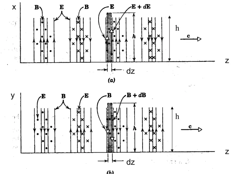
Fig. 8-2. Two views of Traveling EM Plane Wave:
(a) xz plane showing E field (b) yz plane showing B (or H) field
h
Applying Faraday’s Law of Induction around shaded contour in (a)
l
E
x
d
t
d
d
C
Note there is NO contribution around top and bottom of the closed
rectangular loop “C”, which has width “dz” and height “h”, since E = Exix is perpendicular to top and bottom loop segments. Thus the left-hand side of (8-1) may be written as:
(8-1)
l
E
x
d
E
x
dE
x
h
E
xh
dE
x
h
C
H
y
dz h
=>t
d
d
dz
h
t
H
yd
d
Both Hy and Ex are functions of both time (t) and space (z). When evaluating dEx/dz we must assume t is constant because Figure(a) is a instantaneous snapshot at a fixed time. Likewise, when evaluating dHy/dt, we must assume that z is a constant, since we are calculating the time rate of change of Hy at a fixed location. To mathematically take this into account, we replace the derivatives in the above
equation by partial derivatives:
(8-2)
Faraday's Law =>
dE
x
h
dz
h
t
H
y
d
d
=>
dE
x
dz
dH
y
dt
E
x
x x z
z dz
dz x
dz
y
Fig. 8-2. Two views of Traveling EM Plane Wave:
(a) xz plane showing E field (b) yz plane showing B (or H) field
h
Applying Ampere’s Circuital Law to the shaded area in (b)
y
H
y
d
t
Ex
s
d
d
d
C
S
(8-3)Left Side of Ampere's Circuital Law
y
H
y
d
H
y
dH
y
h
H
y
h
h
dH
yC
Right Side of Ampere's Circuital Law
Assuming Ex is
uniform over surface S
t
E
xs
d
d
d
dE
xdt
h dz
We assume a
nonconducting medium (σ = 0) so the conduction current term
(8-4)
Thus Ampere's Circuital Law yields
h
dH
y
dE
xdt
h dz
=>
H
y
z
E
x
t
Differentiating (8-2) with respect to z, exchanging the order of differentiation, and substituting in (8-4) yields
Recalling Equation (8-2):
E
x
z
H
y
t
(8-2)
2Ex
z
2
z
H
y
t
t
H
y
z
t
E
x
t
=>
2Ex
z
2
2Ex
t
2
This the “free space” E-field
In similar fashion, we may find a wave equation for the magnetic field “Hy” by differentiating (8-4) with respect to distance (z),
changing the order of differentiation, and substituting in (8-2).
2
Hy
z
2
dz
E
x
t
dt
E
x
z
dt
dH
ydt
d
2H
ydt
2
=>
2
Hy
z
2
d
2
H
ydt
2
(8-6)Solution to Plane Wave Equation
The solution to (8-5) is given by
E
x
z t
f t
z
g t
z
Where f and g are arbitrary functions of the space-time arguments
E
x
E
z t
x
z t
f t
f t
z
z
g t
and
g t
z
z
Thus the wave equation has an infinite number of possible solutions!
The specific shape of f and g corresponding to a particular situation is dictated by the wave shape of the source current, i(t), that flows in the antenna wire.
Verification of Solution to Plane Wave Equation
Start with the proposed solution
E
x
z t
f t
z
g t
z
For notational convenience, let
u
t
z
and w
t
z
Thus
E
xf u
g w
where u and w are functions of z and t Using chain differentiation:dE
xdz
df
du
du
dz
dg
dw
dw
dz
=>d
2E
xdz
2d
2f
du
2du
dz
2
df
du
d
2u
dz
2
d
2g
dw
2dw
dz
2
dg
dw
But note:
du
dz
dw
dz
d
2
u
dz
2
d
2
w
dz
2
0
d
2
E
x
dz
2
d
2
f
du
2
d
2
g
dw
2
d
2
f
du
2
du
dt
2
d
2
g
dw
2
dw
dt
2
(=1)
(=1)
d
2
E
x
dz
2
d
2
f
dt
2
d
2
g
dt
2
d
2
E
x
dt
2
Interpretation of solution to plane wave equation
f t
z
(be it a sinusoid, a rectangular pulse, a triangular pulse, etc.) represents a
traveling wave moving in the positive z direction, and will thus be called the “+” wave. To illustrate this, imagine that we desire to “follow” a certain point on the waveform. At time t1, let us imagine this point on the waveform is at
position z1. Then at a later time t2, this point moves to position z2. Since we are following a specific point (or specific value of f), we require
The general function
f t
1
z
1
f t
2
z
2
Since f is arbitrary, we must, in turn, require that
Thus the velocity of that point (and hence the velocity of the entire traveling wave) must be given by
v
p
z
t
z
2
z
1
t
2
t
1
1
This is the standard value of the
“speed of light”
For an electromagnetic wave in free space
0
10
9
36
F
m
0
4
10
7
H
m
v
p_air
1
0
0
v
p_air
3 10
8
m
s
In glass
r
5.0
r
1.0
v
p_glass
1
r
0
r
0
v
p_glass
1.342 10
8
m
s
In distilled water
r
80.0
r
1.0
v
p_water
1
r
0
r
0
v
p_water
3.354 10
7
m
s
g t
1 z1
g t
2 z2
t1 z1 t2 z2
vp z t
z2 z1 t2 t1
1
Likewise, the function
g t
z
Represents a wave traveling in the –z direction with the same speed:
The superposition (sum) of functions f and g represents the most general solution to the wave equation, where the f function represents a forward moving wave component away from the radiating source, and the presence of the g function represents a reflected wave moving back toward the
radiating source. If no reflections are present, the g function will be zero.
Finding Hy from Ex: Intrinsic Impedance “η”
Ex
z
Hy
t
Ex
z
f t
z
t z
t z
z
g t
z
t z
t z
z
Hy
t
Ex
z
f t
z
t z
g t
z
t z
Hy
t
We can find a corresponding traveling wave solution for Hy by substituting (8 - 7), which is our solution for Ex into either (8 - 4) or (8 – 2).
Since we are applying this equation at a fixed point in space, z = constant, so
t
t z
t z
Multiplying through by δt and then integrating both sides yields
H
y
1
f t
z
1
g t
z
where
Note that the (+z) progressing Ex wave component “f” (= Ex+) must be
scaled (divided) by +η to turn it into the corresponding Hy (+z)
progressing wave. In similar fashion, the (-z) progressing Ex wave component “g” (= Ex-) must be divided by –η to turn it into the
corresponding Hy (-z) progressing wave.
The units of η must be (V/m) / (A/m) = Ohms. Thus η is called the
“intrinsic impedance” of the medium. Note that
η
sets the ratio between the positive-moving Ex and Hy waves. Likewise,-η
sets the ratiobetween the negative-moving Ex and Hy waves. Since Ex+ / η = Hy+ and Ex- / -η = Hy
-For a wave in free space or air,
0
0
Sinusoidal EM Waves
• The shape of the f and g functions is determined by the wave shape of i(t) that flows in the radiating source (antenna).
• A sinusoidally time-varying source makes f and g take on a sinusoidal form, while a digital pulse generating source makes f and g take on the form of a rectangular pulse.
• For a sinusoidal source, the resulting EM wave moving in the +z direction is:
ω = angular frequency in radians/second of Ex at a fixed point in space (where z = constant) β = “phase constant” in radians/meter
= rate at which phase of wave changes with distance in a “snapshot” of Ex at a fixed instant
of time (where t = constant)
WHERE
E x A cos
t z
A cos t z
Note: for a fixed time (t = constant => a “snapshot” of Ex), the
traveling wave will vary through one complete sinusoidal cycle when βz changes through 2π radians. Thus the length of one complete cycle of the wave, frozen at an instant of time, is called the
“wavelength” (λ), where
λ = 2π / β
Note the velocity of propagation of the wave is
v
p
1
E
x
A cos
t
z
Also, the phase constant is
Example:Consider the EM wave Ex = 2cos(4πt – πz) => ω= 4π r/s, β = π r/m Note that this implies
λ = 2π/ β = 2 m (=>one complete Ex(z) cycle every 2 meters for fixed time “snapshot”) vp = ω/β = 4 m/s (Every ¼ second, the wave moves 1 meter in the +z direction)
Note that from the fixed-time “snapshots” of Ex(z) shown here that the
wavelength of the
propagating wave (the length of one complete cycle of Ex(z)) is λ = 2m, and that reference point “A” travels at 4 m/s, or 1 m every ¼ second, as predicted above.
t0
0 0.5 1 1.5 2 2.5 3 2
0 2
2cos4 t z
z
t 1
4.
0 0.5 1 1.5 2 2.5 3 2
0 2
2cos4 t z
z t 2 4. 0 2
2cos4 t z
A
A
Uniform Plane Waves in Lossy (Electrically Conductive) Medium
•
Of special interest in EMC problems is how plane EM waves attenuate as they
travel through various conductive media, such as sea water, moist earth, or
even various conductors, such as copper or aluminum.
•
In such materials, the electric field component (Ex) in an EM wave sets up
conduction current according to the microscopic form of Ohm’s Law, Jx =
σEx.
•
This induced conduction current serves to partially “short out” the E field
component of the EM wave, and thus attenuates (gradually reduces the
strength) of the EM wave as it propagates through the conductive medium.
•
This attenuation is sometimes undesirable (such as when transmitting a cell
phone signal through a metal wall of a building, or a transmitting a submerged
submarine’s radio communication signal through sea water).
•
But this attenuation is often desirable in RF shielding applications, such as the
use of copper mesh to screen out interfering radio waves in a laboratory’s
“screen room”, or the use of shielded coaxial cable in a cable TV distribution
system, where outer shield on the coaxial cable must be made thick enough and
of the right kind of material in order to successfully shield the transmitted
Sinusoidal Steady-State Lossy EM Plane Wave Equation
E x
z
H y t
Faraday’s Law applied around the closed contour of Fig. 8-2(a) does not change if the medium is conductive, and we still end up with Equation (8-2)
(8 – 2)
But when Ampere’s Circuital Law is applied around the closed contour of Fig. 8-2(b), we must now include the conduction current term involving J (= σE) that was formerly omitted.
0 0.5 1 1.5 2 2.5 3
2 0 2
2cos
4 t z
z
y Hy
d t Ex s
d
d d
Jx s
d S S C y Hy
d t Ex s
d
d d
Ex s
d
Working as before to derive the plane wave equation for a lossy medium:
(8 - 11) Note the additional
conduction current term now present!
Left Side of Ampere's Circuital Law
y Hy
d
Hy dHy
h Hyh hdHyC
Right Side of Ampere's Circuital Law
t Ex s
d d
d
Ex s
d
dEx dt
h dz
Ex
h dz
S S
Thus Ampere's Circuital Law yields
h
dHy dEx dt
Ex
h dz
=>Hy
z
Ex t
Combining the Faraday’s Law result (8-2) with the new
Ampere’s Circuital Law result (8-11)
Plane EM wave equation for conductive medium. Notice the additional “loss”
term that is now present.
2
Ex
z
2
z
H
y
t
t
H
y
z
t
E
x
t
E
x
=>
2
Ex
z
2
2
Ex
t
2
E
x
t
Sinusoidal Steady State Solution to the Lossy Wave Equation
2
E
x
t z
z
2
2E
x
t z
t
2
E
x
t z
t
2
E
x
z
2
2
E
x
j
E
x
Let us solve the wave equation assuming sinusoidal steady state excitation. This permits us to use phasor representation. In phasor form, the lossy wave equation becomes:
(8-12)
(8-13)
Note that Ex is now taken to be the complex-valued phasor representation of the time-domain expression for the electric field, Ex(t,z):
The wave equation (8-12) has been rewritten to remind us that Ex is a “time-domain” function of time and space (t and z)
We begin by postulating a possible solution to this second-order sinusoidal
steady state (phasor) differential equation that varies exponentially with distance:
E
x
A e
z
Substituting this proposed solution into the phasor form of the wave equation (8-13) yields
2
A
e
z
2
A
e
z
j
A
e
z
Dividing both sides by
Ae
γz yields the “characteristic equation”
2
2
j
j
j
j
j
Thus, the complete solution must be the superposition (sum) of
both of these solutions:
E
x
A e
z
B e
z
where
j
j
Note
is defined in terms of the source frequency,
, and
the medium properties,
,
, and
.
(8-15a)
(8-15b)
Physical interpretation of lossy wave equation solution
E
x
t z
Re e
j
t
E
x
j
j
j
Let us define γ as the complex-valued “propagation constant”, and we shall call its real part α and its imaginary part β. We will find that α will be called the “attenuation
constant”, and it dictates how fast the wave’s amplitude exponentially decays (attenuates) with distance as it propagates through the lossy medium. Likewise, we shall call “β” the “phase constant” (just as we have named it already for the lossless case), and it will
indicate the rate at which the phase of the wave changes with distance at a fixed time.
Now let us convert the phasor solution back to the time domain by
multiplying by exp(jωt) and taking the real part:
(8-16)
E
x
t z
Re e
j
t
A e
j
z
B e
j
z
Thus we find that the solution for a plane EM wave in a
conductive (lossy) medium consists of a wave moving in the
“+z” direction and a wave moving in the –z direction.
However, now these two traveling waves no longer have a
constant amplitude as they move, but rather they each decay
exponentially with the distance traveled, as indicated by the
e
-αzterm in the (+z) wave and the e
αzterm for the (-z) wave.
Wave propagating in the +z direction whose amplitude attenuates with
distance traveled.
Wave propagating in the –z direction whose amplitude attenuates with distance traveled.
Intrinsic Impedance of lossy medium
To find the solution for Hy, we may (as for the lossless case) substitute our solution for Ex (8-15a) into (8-2) which is recalled below:
E
x
z
H
y
t
(8-2)Putting this into phasor form,
Ex
z
j
H
y
Solving for Hy and substituting Equation (8-15a)
H
y
1
j
E
x
dz
A
e
z
B
e
z
j
Recalling from (8-15b)
j
j
Substituting this into our expression for Hy
Where
H
y
A e
z
B e
z
j
j
For the lossy medium, note that the intrinsic impedance (for the sinusoidal steady state) is
complex-valued, and may be written in polar form as |η|exp(jθn) This implies in the time domain there is a small phase shift “θn” imparted to the +z progressing and the –z
Approximations for Good Dielectric
|
• Definition of a “Good Dielectric” --- a
medium where the ratio of the magnitude
of conduction current to displacement
current is much less than unity:
|
Conduction Current|/|Displacement Current|
j
j
j
j
1
j
Thus for a good conductor, where
<< 1
j
j
Thus, in a good dielectric, to a high degree of approximation,
and
is approximately 0 => wave propagates with little attenuation The velocity of the wave isv
p
1
Intrinsic Impedance of Good Dielectric
j
j
1
1
j
Thus for a good conductor, where
<< 1
To a high degree of
approximation:
Same result as for the
lossless case!
Approximations for “Good Conductor”
• Definition of a “Good conductor” --- a
medium where the ratio of the magnitude
of conduction current to displacement
current is much greater than unity:
|
Conduction Current|/|Displacement Current|
j
j
j
1
j
<< 1 => j (approximately)
But if we write "j" in polar form as
e
j 2
Then we see that j e
j 2 e j 2
1 2 e j 4 Therefore, to a high degree of approximation, in a conductive medium:
exp j
4
2
1 j
j
2
Thus for a good conductor, there is considerable
loss, since
Also note the phase angle between the time varying
Ex and Hy field at a point in the good conductor is
45 degrees.
Skin Depth in a Good Conductor
• The shielding ability of a good conductor (such as a
copper or aluminum sheet) is indicated by its
skin depth
or
depth of penetration,
which is the depth to which the
Ex and Hy fields penetrate the conductor before they are
reduced in intensity by a factor of exp(-1) = 37%.
• From our solution to the lossy wave equation in the
sinusoidal steady state (8-17), we found that
Thus, the (+z) progressing wave will attenuate as it travels
through the lossy medium in the +z direction:
A e
z
cos
t
z
A e
z
cos
t
z
A e
2
z
cos
t
z
Substituting our expression for the attenuation constant, α
Thus the Ex field will attenuate by exp(-1) = 37% as it travels
a distance
δ is called the skin depth. It decreases with increasing source frequency f,
permeability of the medium μ, and conductivity of the medium σ.
1
2
1
Note the wave’s phase velocity in a lossy medium is still given by
vp = ω / β
But vp is no longer = 1/sqrt(με), which is only valid for lossless or good dielectric materials
In a good conductor, the wave velocity is given by
vp
2
2