Volume 2006, Article ID 59451, Pages1–11 DOI 10.1155/ASP/2006/59451
Face Tracking in the Compressed Domain
Pedro Miguel Fonseca and Jan Nesvadba
Philips Research, 5656AA Eindhoven, The Netherlands
Received 30 August 2004; Revised 23 March 2005; Accepted 4 May 2005
A compressed domain generic object tracking algorithm offers, in combination with a face detection algorithm, a low-compu-tational-cost solution to the problem of detecting and locating faces in frames of compressed video sequences (such as MPEG-1 or MPEG-2). Objects such as faces can thus be tracked through a compressed video stream using motion information provided by existing forward and backward motion vectors. The described solution requires only low computational resources on CE devices and offers at one and the same time sufficiently good location rates.
Copyright © 2006 P. M. Fonseca and J. Nesvadba. This is an open access article distributed under the Creative Commons Attribution License, which permits unrestricted use, distribution, and reproduction in any medium, provided the original work is properly cited.
1. INTRODUCTION
The problem of tracking objects over time is a complex one in computer vision and has been an important topic of re-search over the last few years. Such importance comes from the fact that object tracking enables important applications in areas such as security and surveillance (e.g., tracking peo-ple in restricted areas using security cameras), content man-agement (e.g., in video abstraction to automatically anno-tate video content), content improvement (e.g., helping sta-bilize images in handheld mobile videophones by tracking the location of faces), human-machine interface (e.g., to au-tomatically recognize hand gestures to auau-tomatically execute commands), interactive gaming, and so forth. Requirement constraints such as reliability and computational complex-ity characterize the boundary conditions for a successful and target-platform-suited solution.
The detection and spatial localization of objects, in par-ticular faces, has been broadly investigated [1, 2]. While tracking identified objects throughout uncompressed video sequences, the objects’ spatial properties may be used (e.g., colour, shape, texture, etc.) since it can be expected that they will vary a little from frame to frame. The information is thus represented in a way suited to easily track the objects. However, in compressed video sequences (such as MPEG-1 or MPEG-2), available information may not express directly the objects’ spatial properties and thus, renders the tracking procedure more difficult. In addition, the type of informa-tion that is available actually varies from frame to frame— for example MPEG-1 or MPEG-2 video sequences are typ-ically comprised of I-, P-, and B-frames, each with its own
set of parameters. In this paper we describe an object track-ing solution that uses only compressed parameters available in MPEG-1 or MPEG-2 video sequences while performing only the minimal decoding necessary to retrieve them from the compressed video streams.
Few algorithms exist that are able to perform object tracking in the compressed domain. In [3,4] the proposed object tracking algorithms use forward motion vectors to track objects between a reference (I- or ) frame and a P-or B-frame (where this kind of motion vectP-ors are avail-able). In order to track an object, it is first defined as a set of macroblocks in the reference frame. However, the for-ward motion vectors are available only in the P- or B-frame where the object is being tracked to. So, the object’s dis-placement from the reference frame to the P- or B-frame is determined by computing the mode of the forward mo-tion vectors of the macroblocks at the same posimo-tions (in the latter frame) as those that define the object (in the ref-erence frame). Although simple and not at all computation-ally complex, this solution is only reliable whenever motion is not strong or when motion is uniform over the entire frame.
In the algorithms proposed in [6–9], objects can only be tracked to P- and I-frames, but not to B-frames.
The object tracking algorithm proposed in this paper performs the tracking of objects that are detected and located throughout a group of pictures (GOP) by means of available compressed domain data. We will describe a tracking solu-tion based solely on the use of forward and backward mosolu-tion vectors. A smart weighting and averaging strategy of relevant motion vectors has been proven to be sufficiently reliable for the purpose at hand. Additionally, the solution’s computa-tional complexity is extremely low enabling the implemen-tation on platforms with very strict compuimplemen-tational capacities such as mobile and stationary consumer devices. Although the proposed algorithm allows the tracking of generic ob-jects, it will be described in the context of a face tracking system where the objects being tracked correspond to faces. Faces are detected in I-frames with a compressed domain face detector which is also briefly described.
The organization of this paper is as follows: the next sec-tion describes the face tracking algorithm;Section 3 evalu-ates the algorithm’s computational complexity and the algo-rithm’s performance; and the paper concludes withSection 4.
2. THE FACE TRACKING ALGORITHM
The face tracking algorithm proposed in this paper aims to determine the presence and location of faces in all frames of compressed video sequences where a specific type of com-pressed domain data is available. Naturally, the type of infor-mation available differs according to the type of frames where faces are being located: while in I-frames only DCT informa-tion is available, in P- and B-frames, the type of informainforma-tion available consists mainly of motion vector information. For this reason, the tracking procedure differs according to the frame type.
The proposed face tracking algorithm is illustrated in
Figure 1; in the figure, the location of one face (represented with a dark solid rectangle) is determined over a sequence of frames in a compressed video sequence. In I-frames, where DCT information is available, the presence and location of faces is determined based on the frame’s colour and lumi-nosity (as provided by the DC coefficients) and frequency (as provided by AC coefficients) properties. In all remaining frames, all detected faces are tracked based on the properties of existing motion vectors.
Since in the P- and B-frames available information typi-cally consists of motion vector information, motion-vector-based object tracking is performed to determine the location of previously detected faces.
2.1. Face detection in the compressed domain
The compressed domain face detection algorithm proposed in this paper uses a feature analysis-based approach to deter-mine the presence and location of multiple frontal and ro-tated faces. This procedure is based purely on compressed domain information available in I-frames of MPEG-1 or
I B B P B B I
FODD FODD
BODD FODD
FODD Face location determined by the object tracker
Face location determined by the face detector
Figure1: The face tracking algorithm: the object’s location in P-and B-frames is determined using FODD P-and BODD techniques.
MPEG-2 video sequences (or in JPEG still images). The un-derlying assumption behind the feature analysis-based ap-proach is that properties or features exist that are invariant from face to face. Thus, by detecting specific features such as skin colour and facial features, the presence and location of faces can be determined.
The diagram inFigure 2 represents an overview of the face detector’s architecture and each of the algorithm’s steps. In the figure, an example of the input and output of each step is illustrated.
The face detector’s input corresponds to some AC coeffi-cients and to all DC coefficients taken from the compressed image where detection is to be performed. In order to make the face detection algorithm as robust and independent as possible of the image or video capturing conditions, auto-matic contrast adjustment is applied to each input DC image. Afterwards, skin colour segmentation is applied to the DC colour image resulting from the contrast adjustment stage by determining the Mahalanobis distance [10,11] between each pixel’s value in the DC image and a skin colour model. This skin colour model is built beforehand from the statisti-cal properties, in the normalized RGB colour space, of a large set of manually segmented faces. A binary closing operation with a 3×3 square structuring element, followed by a hole filling operation are applied on the binary image that resulted from the segmentation stage; these binary morphological op-erations are applied to ensure that in most cases a face is com-pletely covered by a binary mask, without any holes in it. An algorithm to label binary connected regions is then applied in order to identify connected regions in the image.
Face candidates validation Face candidates
Face candidates generation
Facial features
localization Feature map construction Location of faces in the image
Feature
map Face images after grey scale dilation (left) and erosion (right)
Vertical (left) and horizontal (right) AC energy maps DC image’s
luminosity component
Contrast adjusted DC colour image
Labelled image with two skin colour regions Contrast
adjustment segmentationSkin colour
Binary closing & hole filling
Connected regions labelling DC image (DC/AC coeCompressed imagefficients) AC coefficients
Figure2: Face detector algorithm’s architecture and examples of the input and output of each of the algorithm’s steps.
of specific facial features. The vertical AC energy map, illus-trated inFigure 2, is built from the AC coefficients indicated inFigure 3(a)and highlights regions of the image that have high vertical variance; on the other hand, the horizontal AC energy map also illustrated inFigure 2is built from the coef-ficients indicated inFigure 3(b)and highlights regions with high horizontal and diagonal variance.
Finally, a feature map is built calculating for each position in the feature map matrix the following value:
feature map(x,y)= dilated(x,y)
eroded(x,y) + 1
×horizontal energy map(x,vertical energy map(x,y) + 1y) + 1. (1)
The first fraction in (1) enhances dark locations surrounded by bright areas (a similar equation is used in [11] to deter-mine the location of the eyes in uncompressed images). The second fraction enhances regions with a high vertical vari-ance and with a low horizontal varivari-ance thus highlighting the presence of facial features (e.g., eyes, eyebrows, mouth) and de-emphasizing locations like the sides of the face (which may as well have high horizontal variance).
In order to determine the location of faces that may ex-ist in each skin colour region previously identified, the loca-tion of facial features is first determined. Facial features are identified directly from the feature map simply by projecting its values on vertical and horizontal axis (a similar technique was used in [12]). Face candidates representing possible lo-cations of faces in the image can now be determined for each skin colour region. These candidates are generated from the location of the features determined from the feature map, according to a model of typical frontal and rotated human faces. Finally, face candidates are ranked after computing a
relevance value to determine which best represents a face. Relevance determination will be based on the size of the face candidate, the face candidate’s percentage of skin colour pix-els and the face candidate’s facial features intensity in the fea-ture map. After computing the relevance of all generated face candidates for each individual skin colour region, the best is determined by choosing the one with the highest relevance for each individual skin colour region.
The face detection algorithm presented here is described in higher detail in [15,16].
2.2. Object tracking
As explained before, object tracking is used in the face track-ing system to determine, in P- and B-frames, the location of previously detected faces. This tracking procedure is per-formed using only compressed domain information—in this case, motion vector information available in macroblocks in these frames.
DC
(a)
DC
(b)
Figure3: Set of AC coefficients for (a) vertical and (b) horizontal and diagonal variance.
motion vector information, objects are tracked using a for-ward object displacement determination technique (as rep-resented by FODD inFigure 1)—forward motion vectors are used to determine the object’s displacement from a previous reference (I- or P-) frame to a B-or P-frame. Both techniques are described in the following.
2.2.1. Backward object displacement determination
Defining SMB as the set of macroblocks (MBs) that comprise the object letSMVrepresent the set of backward motion vec-tors (BMVs) corresponding to the macroblocks that define the object,
SMV=MV1,. . .,MVn, (2)
wherenis the number of macroblocks that define the object being tracked. If this set is empty (n=0), meaning that no BMVs exist for the MBs that comprise the object, no object displacement vector can be determined and the face cannot be tracked further.
Let a motion vector be defined by itsx- andy -compo-nents, that is,
MV=(MVx,MV y). (3)
The setsSMVxandSMV ycan now be defined, representing the set ofx- andy-components, respectively, for the motion vectors corresponding to the macroblocks that comprise the object being tracked:
SMVx=MVx1,. . .,MVxn, SMV y=MV y1,. . .,MV yn.
(4)
In order to determine the object’s displacement, a displace-ment vector is determined from the mean information asso-ciated with the set of the object’s backward motion vectors.
The mean backward displacement vector,DVmean, is a vector whose x- and y-components are determined as the
average1of thex- and y-components of the motion vectors taken from theSMVxandSMV ydefined before, that is,
DVmean=DVx,DV y (5)
with
DVx=
n
i=1MVxi
n , DV y=
n
i=1MV yi
n , (6)
whereMVxiandMV yiare theith values of theSMVxand SMV ysets defined before.
If the objects are not moving, the mean backward dis-placement vector will have both components equal to zero and the tracking algorithm will simply indicate the same location as indicated in the previous frame—the algorithm should not fail to track faces when they are not moving.
Although the proposed algorithm is not used to track ob-jects to I-frames (since object—in this case, face-detection takes place in those frames), it should be noted that the back-ward object displacement determination technique just de-scribed could be used to determine the object’s displacement from a B-frame to a future reference I-frame—in case no detection algorithms were available, the proposed solution would be much less computationally complex than the tech-nique proposed in [6] where block matching is needed in or-der to extract motion features for the I-frames.
Additionally, it should be noted that the computation of displacement vectors from backward motion vectors actually increases the tracking algorithm’s robustness to strong mo-tion: by allowing for an object’s position in a P-frame to be determined from a B-frame rather than from a previous P-or I-frame, the number of frames between the frame where the object is being tracked from to the frame where the object is being tracked to can be much smaller. This enhancement will be particularly noticeable in sequences where between
each reference (I- or P-) frame, a relatively high number of B-frames exist (e.g., I B B B P B B B. . .)—in this case, the P-frame is distant from the previous reference P-frame and thus, the motion vectors may not be able to correctly express an object’s motion, especially if the motion is strong.
2.2.2. Forward object displacement determination
For each macroblock in a P- or B-frame, a forward motion vector may exist to indicate the prediction of the location of that macroblock in a previous I- or P-frame. In the pro-posed object tracking algorithm, forward motion vectors are used to track objects to B-frames; additionally, they can be used to track objects to P-frames in case backward object-displacement determination techniques are not being used or in case no backward motion vectors exist that allow the object to be tracked from a B-frame to a P-frame. In any case, forward motion vectors allow for an object’s displacement from an I- or P-frame to a B- or P-frame to be determined.
The object may be defined as a set of macroblocks in pre-vious reference I- or P-frames. However, (forward) motion vector information is only available for macroblocks in the current frame. On the other hand, the object can only be tracked from the previous reference frame to current frame if the macroblocks—which comprise it—have some kind of motion information that predicts in some way their location in the current frame. Because the motion information is not readily available, the problem of determining a displacement vector using forward motion information is much different from that found while determining a displacement vector us-ing backward motion vector information (as described in the previous section).
The displacement vector will also be determined from a set of motion vectors. However, since motion vector information—relating the frame where the object is being tracked from to the frame where the object is being tracked to—is available only in the latter, forward motion informa-tion needs to be somehow “projected” to the reference frame. In other words, each macroblock that defines the object in the reference frame will need a kind of motion vector that indicates its “backward” prediction in the current frame. For that purpose, a forward motion vector map is built for the reference frame, based on which the forward object’s dis-placement vector will be determined. This forward motion vector map consists of a set of lists, built for each macroblock in the reference frame. Each one of these lists corresponds to a set of inverted forward motion vectors (IFMVs) repre-senting the backward prediction of a reference frame’s mac-roblock in the current frame and an associated “confidence” value for that prediction.
Following the nomenclature used inFigure 4, the for-ward motion vector map determination procedure will now be explained.
A macroblockiis defined by thex- andy-coordinates of its leftmost and topmost pixel,MBxiandMByi, respectively
MBi=MBxi,MByi (7)
MBRj
MBip
MBRjMBip
IMVj
MVi MBi
Past reference (I- or P-) frame
Current (P- or B-) frame Figure4: Forward motion vector map determination.
and by its dimensions which are constant and correspond to 16 luminance pixels of both width and height.2
LetMVi represent the forward motion vector of mac-roblockiin the current (P- or B-) frame,
MVi=MVxi,MV yi, (8)
whereMVxiandMV yiare itsx- andy-components, respec-tively.
Using the forward motion vector MVi from the cur-rent frame, macroblockican be “projected” to the reference frame simply by shifting that macroblock’s position by the corresponding forward motion vector. Let MBip represent the projection of macroblockiin the reference frame,
MBip=(MBxi+MVxi,MByi+MV yi, (9)
and letMBRjrepresent a macroblockjin the reference frame that is overlapped by the projection of macroblocki3in the reference frame, such that
MBRj∩MBip=φ (10)
withMBRjdefined by the coordinates of its leftmost topmost pixel,
MBRj=MBRxj,MBRyj. (11)
Now, letIMVjrepresent the inverted forward motion vector of a current frame’s macroblock ioverlapping macroblock MBRjin the reference frame
IMVj=IMVxj,IMV yj,OPj (12)
2The macroblocks’ dimensions for the chrominance components can be different: if subsampled horizontally by 2, each macroblock’s width will correspond to 8 pixels; if subsampled vertically by 2, each macroblock’s height will correspond to 8 pixels.
MB3p
MB4p
MB1p
MB2p
MV1
MV2
MV3
MV4
MB3
MB4
MB1
MB2
Past reference (I- or P-) frame
Current (P- or B-) frame (a)
Reference frame macroblock
MBk
SIMVk Inverted forward
motion vectors
Backward predictions
Current (P- or B-) frame
(b)
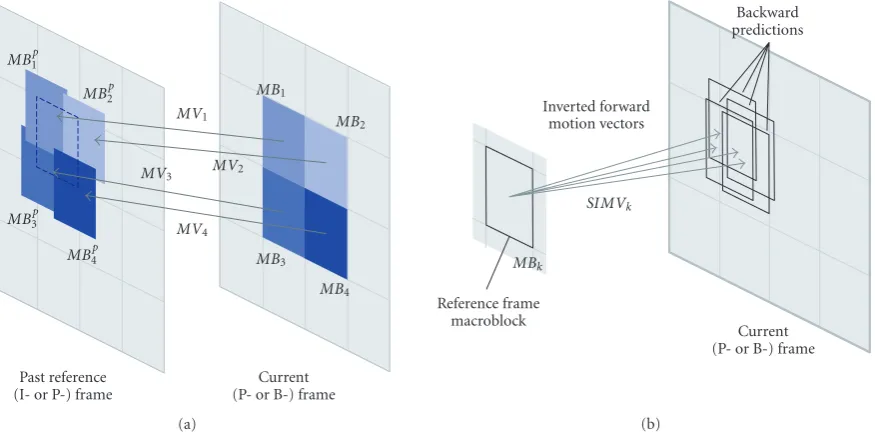
Figure5: (a) Projection of four current frame’s macroblocks on a past reference frame; (b) inverted forward motion vectors determined for the reference frame macroblock indicated in (a) and its corresponding backward predictions on the current frame.
with
IMVxj= −MVxi, IMV yj= −MV yi,
OPj=areaMBRj∩MBip, (13)
whereIMVxj andIMV yj represent thex- and y-compo-nents of the inverted forward motion vector from mac-roblocki andOPj represents the overlap percentage value indicating “how much” of the projected macroblockMBip
overlapsMBRj.
Figure 5(a)illustrates the projection of four macroblocks from the current frame to a past reference frame; associated with each of these macroblocks is a forward motion vector— as can be seen, the macroblock in the reference frame indi-cated with the black dotted square is overlapped by four pro-jections. Figure 5(b)illustrates the list of inverted forward motion vectors determined for that macroblock in the ref-erence frame—since more than one projection overlapped the macroblock (as inFigure 5(a)), more than one inverted forward motion vector exists for that reference frame mac-roblock; these inverted forward motion vectors thus indi-cate an estimate of the (backward) prediction of the reference frame macroblock in the current frame.
A complete forward motion vector map will consist of a list of inverted forward motion vectors, like those defined in (12), for each macroblock in the reference frame—the list of inverted forward motion vectors for the macroblockMBk inFigure 5(b)corresponds to the set of inverted forward mo-tion vectors and the associated overlap percentages, indicated asSIMVk.
For each of these macroblocks, the list of inverted for-ward motion vectors may have more than one element since more than one macroblock in the current frame could have had a projection overlapping the same macroblock in the
reference frame. Like described before, associated with each inverted forward motion vector, is an overlap percentage value indicating “how much” of the macroblock was over-lapped by the current frame projected macroblock to which the inverted motion vector corresponded. It follows naturally that the higher the overlap percentage value is for an inverted motion vector, the more likely it will be that the vector in-dicates a good backward prediction for that macroblock in the current frame. On the contrary, a low overlap percent-age value associated with an inverted forward motion vec-tor will give no guarantee whatsoever about the “quality” of the backward prediction for that macroblock in the current frame. This overlap percentage value thus indicates a “con-fidence” value regarding the backward prediction of a given macroblock in the reference frame.
The displacement of an object from the reference frame to the current frame can now be determined from the set of inverted forward motion vectors. Defining the object as a set of macroblocks in the reference frame, the set of inverted for-ward motion vectors from where the object’s displacement is computed corresponds simply to the union of the sets of in-verted forward motion vectors,SIMVk,for each of the mac-roblocks that comprise the object.
LetSMB represent the macroblocks that define the ob-ject in the reference frame. Now, letSIMVkrepresent the set of inverted forward motion vectors for macroblockkin the reference frame,
SIMVk=IMVk1,. . .,IMVkkmax
, (14)
Table1: Face detection and face tracking algorithms’ complexity.
Face detection Face tracking
Resolution MIPS Mcycle/s MIPS Mcycle/s
PAL D1 7.53 20.95 9.22 25.95
VGA 5.58 15.52 6.83 19.22
SIF 1.53 4.27 1.88 5.29
A global set of inverted motion vectors for the entire ob-ject, SIMV, can now be built from the union of the sets SIMVkfor the various macroblocks that define the object in the reference frame,
SIMV=
m SIMVm ∀m
:MBm∈SMB. (15)
Situations may occur where no inverted forward motion vec-tors exist in the global setSIMV. This situation occurs if the macroblocks in the current frame have no forward motion vectors. In this case, no forward object displacement can be determined, the object’s location in the current frame cannot be determined and naturally faces cannot be tracked further. In order to determine the object’s displacement, a dis-placement vector is determined from the mean4information of the global set of inverted forward motion vectors,SIMV. The mean inverted forward displacement vector,IDVmean, is a vector whosex- and y-components are determined as the average of thexandycomponent values from the global set SIMV defined before, weighted by the corresponding over-lap percentage values, that is,
IDVmean=IDVx,IDV y (16)
with
IDVx=
qmax
i=1IMVxq·OPq qmax
q=1 OPq ,
IDV y=
qmax
i=1IMV yq·OPq qmax
q=1 OPq ,
(17)
where qmax is the number of inverted motion vectors in the global setSIMV, andIMVxq andIMV yq represent the x-andy-components, respectively, of theqth inverted forward motion vector inSIMV.OPqrepresents the overlap percent-age value associated with theqth inverted forward motion vector inSIMV.
As explained, the overlap percentage value provides an indication of the “confidence” associated with the predic-tion of a reference frame’s macroblock in the current frame. Therefore, by weighting the average with this overlap per-centage value, inverted forward motion vectors with higher
4Besides the mean, the mode and the median information were also com-puted from the set of inverted forward motion vectors. Experiments have shown, however, that using the mean computation will yield the best re-sults.
“confidence” will weigh more in the computation of the ob-ject’s displacement vector whereas lower “confidence” mo-tion vectors will influence the displacement vector’s compu-tation less.
Again, if the objects are not moving, the mean inverted forward displacement vector will have both components equal to zero and the tracking algorithm will simply indicate the same location as indicated in the previous frame—the al-gorithm should not fail to track faces when they have stopped moving.
3. COMPUTATIONAL COMPLEXITY AND PERFORMANCE ANALYSIS
In order to determine the face tracking algorithm’s computa-tional complexity, that is, the required number of instruc-tions per second, face tracking (comprising both the face detector and the object tracker) is considered to be applied on an ARM9-based platform, performing real-time track-ing across all frames of an MPEG-2 video sequence, with a frame rate of 25 frames per second and a GOP size of 6. The face detection (alone) and face tracking algorithms’ com-putational complexities—measured in millions of instruc-tions per second (MIPS) and in millions of cycles per sec-ond (Mcycle/s)—are indicated inTable 1. As it can be eas-ily seen, the face detection algorithm alone is extremely in-expensive, being able to detect and locate faces in I-frames of compressed video sequences. With a small increase (ap-proximately 25% for PAL D1 resolution) of complexity, the complete face tracking algorithm (face detection and object tracking) is able to determine the location of faces in all frames of compressed video sequences. The proposed algo-rithms are thus extremely inexpensive and adequate for use in low-performance CE devices, using less than 10% of an ARM9 processor’s capacity for face tracking in frames with VGA resolution.
In order to analyse the algorithm’s tracking performance, tests were performed on two home-video sequences—in-doors and outsequences—in-doors. The sequences were captured under dif-ficult and heterogeneous light conditions. The subjects were recorded with frontal and nonfrontal poses and with differ-ent facial expressions, a variety of hairstyles, and some of the subjects had a beard and glasses. Both sequences were en-coded in MPEG-2 with a GOP size of 6. A face is consid-ered to be detectable if it is tilted below an angle of±20 de-grees, rotated below an angle of±80 degrees and if most of the face’s colour corresponds to skin colour.
Table2: Face detection and face tracking performance results.
Face detection Face tracking
Test
sequence Frames Faces
Correct locations
Missed faces
False
locations Recall Precision Frames Faces
Correct locations
Missed faces
False
locations Recall Precision
Indoors 736 335 311 24 68 0.93 0.82 4416 1973 1771 202 502 0.90 0.78
Outdoors 541 159 149 10 34 0.94 0.81 3246 950 868 82 230 0.91 0.79
Global 1277 494 460 34 102 0.93 0.82 7662 2923 2639 284 732 0.90 0.78
Figure6: Examples of faces correctly detected with the described algorithm.
this criterion, the location of faces in each frame are manually annotated and classified according to the following classes:
(i) acorrect locationis considered when the bounding box representing the face location as determined by the face tracking algorithm covers approximately at least half of the face or encloses completely at least one visi-ble facial feature;
(ii) afalse locationis considered when the bounding box representing the face location does not satisfy any of the two previous conditions, that is, when something that is not a face is erroneously located as such; (iii) amissed faceis considered when a face appears in the
image, it is considered to be detectable but it is not un-der the bounding box of a correct location.
The tracking algorithm’s performance, according to this matching criterion, will be evaluated in terms of the ratio of correct locations against the number of detectable faces, as expressed by therecallmetric,
recall= correct
correct + missed, (18) wherecorrectandmissedcorrespond to the number of cor-rect and missed locations, respectively, classified according to the criterion defined above.
Additionally, the algorithm’s performance will also be evaluated in terms of the ratio between the number of correct detections and the total number of detections (i.e., correct and false detections), as expressed by theprecisionmetric,
precision= correct
correct + false, (19)
wherecorrectandfalsecorrespond to the number of correct and false locations, respectively, classified according to the criterion defined above. The precision metric expresses the capability of the tracking algorithm to determine only cor-rect locations while avoiding false alarms. Notice that the recall metric expresses the capability to locate all the de-tectable faces regardless of the number of false locations in-dicated.
The performance results for both the face detection and the object tracking algorithms were obtained after visually analysing the detection and tracking results on each single frame and, using the criterion defined above, counting the number of correct and false locations and the number of missed faces.
Table 2 indicates the detection (in I-frames) and the
tracking results (in all frames) for each of the two video sequences. As it can be seen, the face detection algorithm achieves a very high recall value of 93% and a slightly lower precision value of 82%. The performance of the tracking al-gorithm naturally depends on the performance of the detec-tion algorithm (faces that are not detected will not be tracked and false detections will naturally lead to false locations by the tracking algorithm). By using only motion information to track faces throughout each GOP, the tracking algorithm achieves a still extremely high recall value of 90% and a pre-cision value of 78%. The performance decreases only slightly when compared to the detection performance. However, the location of faces may now be determined for all frames of the video sequences.
(a) (b) (c)
(d) (e) (f)
Figure7: Example of a face correctly tracked for the entirety of a shot comprised of 22 GOPs; for each of the indicated GOPs, two figures are illustrated: the result of detection in the first (I) frame of the GOP (on the left) and the result of tracking at the last frame of the GOP (on the right). (a) GOP1, (b)GOP2, (c) GOP3, (d) GOP20, (e) GOP21, and (f) GOP22.
Figure8: Example of the result of face tracking in a GOP with strong camera motion; the bounding box in the first frame, in the left, corresponds to the result of face detection.
the detection algorithm is able to detect rotated and titled faces.
Figure 7illustrates an example of a correctly tracked face for an entire shot comprised of 22 GOPs. The tracking algo-rithm is able to cope with camera pan, zoom, and even par-tial occlusion of the face.Figure 8illustrates an example of a sequence where the face tracking algorithm is not able to cor-rectly locate the face being tracked throughout all frames of a GOP with strong camera motion. This is due to the fact that in this particular sequence the motion vectors are not able to correctly express the objects’ motion, and thus, tracking is not performed correctly. The same figure highlights another situation where the tracking algorithm naturally fails, that is, when a new face appears in the middle of the GOP. Naturally, since the only faces that can be tracked are those that were de-tected, a newly appearing face will only be tracked from the moment it is detected in an I-frame.
4. CONCLUSIONS
This paper proposed a compressed domain object tracking algorithm, which, combined with a face detection algorithm that also acts in the compressed domain, allows for faces to be tracked throughout video sequences where a specific type of compressed domain data is available (such as MPEG-1 or MPEG-2 video sequences). Using only DCT coefficients to detect faces in some frames and motion information as
provided by forward and backward motion vectors in the remaining frames, the proposed algorithm offers a process-ing power efficient, inexpensive, fast, and sufficiently reliable solution for object tracking for various consumer electronic applications. The solution’s processing power efficient na-ture enables even its implementation on portable and mobile platforms for applications such as face image stabilization for mobile video conferencing.
The complete face tracking algorithm’s performance was analysed after performing face tracking on two home-video sequences. These sequences were considered to be represen-tative of the typical content in applications for which the developed face tracking algorithm was originally devised— compressed home-video sequence analysis for content man-agement in low-power CE devices. The face tracking algo-rithm’s recall measure was found to be high (90%) while its precision was found to be slightly lower (78%). While it was shown that the tracking algorithm depends on the perfor-mance of the detection algorithm, its perforperfor-mance was found not to decrease significantly when compared to the latter. In fact, with only a small increase of complexity, the location of faces may be determined with sufficient accuracy for all frames in compressed video sequences.
publicly available content nor is there any publicly avail-able code of their implementations. For future work, the proposed algorithm’s performance will be analysed under known video sequences and possible comparisons will be made against existing face detection and face tracking algo-rithms.
In conclusion, the novelty of the face tracking algorithm proposed resides in the use of backward motion vectors to allow tracking to be performed from B-frames to (I- or P-) reference frames. The algorithm should thus be more robust to strong motion than previously proposed algorithms. Be-sides, it now allows for the tracking of objects to I-frames.
Additionally, the algorithm cleverly uses inverted motion vectors weighted by overlap areas to track objects using for-ward motion vectors. This strategy allows for the computa-tion of a weighted average of inverted mocomputa-tion vectors, where the weight is given by the overlap percentage value, which, as explained, acts as an indication of “confidence.” Thus, mo-tion vectors with higher confidences will weigh more in the displacement vector computation. This technique has been experimentally proven to yield better performance than the typical mode value computation used in previously proposed algorithms. Besides being sounder, it is much less computa-tionally complex than existing techniques.
REFERENCES
[1] E. Hjelm˚as and B. K. Low, “Face detection: a survey,”Computer Vision and Image Understanding, vol. 83, no. 3, pp. 236–274, 2001.
[2] M.-H. Yang, D. J. Kriegman, and N. Ahuja, “Detecting faces in images: a survey,”IEEE Transactions on Pattern Analysis and Machine Intelligence, vol. 24, no. 1, pp. 34–58, 2002.
[3] R. Achanta, M. Kankanhalli, and P. Mulhem, “Compressed domain object tracking for automatic indexing of objects in MPEG home video,” inProceedings of IEEE International Con-ference on Multimedia and Expo (ICME ’02), vol. 2, pp. 61–64, Lausanne, Switzerland, August 2002.
[4] J. Wang, R. Achanta, M. Kankanhalli, and P. Mulhem, “A hier-archical framework for face tracking using state vector fusion for compressed video,” in Proceedings of IEEE International Conference on Acoustics, Speech, and Signal Processing (ICASSP ’03), vol. 3, pp. 209–212, Hong Kong, April 2003.
[5] D. Schonfeld and D. Lelescu, “VORTEX: video retrieval and tracking from compressed multimedia databases: affine trans-formation and occlusion invariant tracking from MPEG-2 video,” inStorage and Retrieval for Image and Video Databases VII, vol. 3656 ofProceedings of SPIE, pp. 131–142, San Jose, Calif, USA, January 1998.
[6] L. Favalli, A. Mecocci, and F. Moschetti, “Object tracking for retrieval applications in MPEG-2,”IEEE Transactions on Cir-cuits and Systems for Video Technology, vol. 10, no. 3, pp. 427– 432, 2000.
[7] V. Mezaris, I. Kompatsiaris, N. Boulgouris, and M. G. Strintzis, “Real-time compressed-domain spatiotemporal segmentation and ontologies for video indexing and retrieval,”IEEE Trans-actions on Circuits and Systems for Video Technology, vol. 14, no. 5, pp. 606–621, 2004.
[8] Y. Nakajima, A. Yoneyama, H. Yanagihara, and M. Sugano, “Moving object detection from MPEG coded data,” in Vi-sual Communications and Image Processing ’98, vol. 3309 of
Proceedings of SPIE, pp. 988–996, San Jose, Calif, USA, January 1998.
[9] W.-N. Lie and R.-L. Chen, “Tracking moving objects in MPEG-compressed videos,” inProceedings of IEEE Interna-tional Conference on Multimedia and Expo (ICME ’01), pp. 965–968, Tokyo, Japan, August 2001.
[10] V. Vezhnevets, V. Sazonov, and A. Andreeva, “A survey on pixel-based skin color detection techniques,” in Proceedings of International Conference on Computer Graphics & Vision (GraphiCon ’03), pp. 85–92, Moscow, Russia, September 2003. [11] R.-L. Hsu, M. Abdel-Mottaleb, and A. K. Jain, “Face detec-tion in color images,”IEEE Transactions on Pattern Analysis and Machine Intelligence, vol. 24, no. 5, pp. 696–706, 2002. [12] K. Sobottka and I. Pitas, “A novel method for automatic face
segmentation, facial feature extraction and tracking,”Signal Processing: Image Communication, vol. 12, no. 3, pp. 263–281, 1998.
[13] A. Nikolaidis and I. Pitas, “Facial feature extraction and de-termination of pose,” inProceedings of NOBLESSE Workshop on Non-Linear Model Based Image Analysis (NMBIA ’98), pp. 257–262, Glasgow, Scotland, UK, July 1998.
[14] Y. Zhang and T.-S. Chua, “Detection of text captions in com-pressed domain video,” inProceedings of ACM Workshops on Multimedia (ACM MM ’00), pp. 201–204, Los Angeles, Calif, USA, October 2000.
[15] P. Fonseca and J. Nesvadba, “Face detection in the compressed domain,” inProceedings of IEEE International Conference on Image Processing (ICIP ’04), vol. 3, pp. 2015–2018, Singapore, October 2004.
[16] J. Nesvadba, R. Kleihorst, J. Fan, P. M. Fonseca, and H. Broers, “Face related features in consumer electronic (CE) device en-vironments,” inProceedings of IEEE International Conference on Systems, Man and Cybernetics (SMC ’04), vol. 1, pp. 641– 648, The Hague, The Netherlands, October 2004.
Pedro Miguel Fonseca has obtained his B.S. degree in electrical and computer en-gineering in 2002 from the Instituto Supe-rior T´ecnico in Lisbon, Portugal. In 2004 he obtained his M.S. degree in electrical and computer engineering after completing an internship in Philips Research where he worked on face detection and face track-ing in compressed video content. In 2004 he joined Philips Research as a Research
Scien-tist and has worked since then on algorithms for multimedia con-tent analysis, pattern recognition, signal processing, and computer vision. He has also been involved in the design of system archi-tectures for distributed content analysis and in the specification of future generations of ICs for video processing and encoding. He is actively involved in national and international research projects (MultimediaN, CANDELA) and has published several conference and journal papers in his field of research.