Original Article
Three-dimensional finite element
analysis of ankle arthrodesis
Qiang Xie1, Wenyi Liu2, Zhihui Wang3, Yunfeng Gao1, Xinxin Xue1
1Department of Hand and Foot Surgery, Affiliated Hospital of Chengde Medical College, Chengde, P. R. China;
Departments of 2Social Sciences, 3Joint Surgery, Chengde Medical College, Chengde, P. R. China
Received April 28, 2017; Accepted July 6, 2017; Epub August 15, 2017; Published August 30, 2017
Abstract:Background: Ankle arthrodesis is the gold standard and most commonly used method for the treatment of post-traumatic ankle arthritis. Aims: This study is to investigate the biomechanical safety and stability of four
ankle fusion models through three-dimensional finite element analysis. Methods: Four ankle fusion models were established, including anterior plate ankle fusion model, lateral plate ankle fusion model, anterior plate plus pos-terolateral screw ankle fusion model and lateral plate plus pospos-terolateral screw ankle fusion model. The four
move-ment modes of the ankle internal rotation, external rotation, dorsiflexion and neutral mode were respectively simu -lated. The maximum displacement of the fusion surface and the stress of four movement modes were measured and analyzed. Results: The anterior plate plus posterolateral screw ankle fusion model had significantly decreased
maximum surface displacement at all four movement modes than the anterior plate ankle fusion model (P<0.05). The maximum surface displacement of the lateral plate plus posterolateral screw plate ankle fusion model was
sig-nificantly reduced at all four movement modes than that of the lateral plate ankle fusion model (P<0.05). Similarly,
the stress peak of bone, plate and screw in the anterior/lateral plate plus posterolateral screw ankle fusion model
was significantly reduced than that in the anterior/lateral plate ankle fusion model at the internal rotation state, the external rotation state and the dorsiflexion state, respectively (P<0.05). There was no significant difference at the
neural state. Conclusion: The anterior/lateral plate plus posterolateral screw ankle fusion models have better fusion safety and higher fusion stability.
Keywords: Ankle arthritis, ankle arthrodesis, ankle fusion, three-dimensional finite element, plate, biomechanical
Introduction
Post-traumatic ankle arthritis often causes ankle pain and dysfunction if left untreated [1, 2]. Surgery, including ankle arthrodesis and ankle arthroplasty, is the main therapeutic method for post-traumatic ankle arthritis [1, 3]. And, ankle arthrodesis is the gold standard and most commonly used method [4-6]. There are more than 40 types of ankle arthrodesis [7-12].
The internal fixation is the preferred choice for
most patients [13]. However, the healing of ankle fusion is hard to achieve and is still the biggest problem for ankle arthrodesis. It is
reported that the three screw fixation has
achieved good fusion rates. For example, Holt
et al. [14] found that the best fixation was achieved when the first screw was placed from
the posterior malleolus into the neck. Ogilvie et al. [15] argued that one lateral screw should be
first placed to achieve good fixation during three screw fixation. Thus, the posterior screw and
the lateral screw are of great importance for
three screw fixation.
Plate ankle fusion is another widely used meth-od for ankle fusion and has shown gometh-od clinical
efficacy [16]. At present, the type of steel plate
used mainly includes the anterior steel plate, the lateral steel plate and the posterior steel plate. Kakarala et al. [17] suggested that cross
screw fixation plus the anterior contoured plate could produce stable internal fixation for ankle
arthrodesis. However, there is no report on the biomechanical analysis of this combined ankle fusion method.
In the present study, we investigated the biome-chanical properties of four different ankle
-ment analysis. Our findings may provide a bet -ter solution for the optimization of ankle arthrodesis and lay a theoretical foundation for further clinical research.
Materials and methods Subject
One male volunteer was enrolled in this study. This volunteer was healthy, with age of 30. Ankle trauma and other related medical history were ruled out. This volunteer had been informed about the details of the experiment. Prior written and informed consent were obtained from this volunteer and the study was
approved by the ethics review board of Affiliated
Hospital of Chengde Medical College. CT scanning
CT scanning was performed with Philip To- moscans R7000 64 SCT. The right ankle joint was scanned. Data were saved and exported in
solid modeling function of the Abaqus 2016
finite element analysis software, the screws were simplified. The threads were ignored and
the screw trucks were replaced with 6.5 mm diameter cylinders. The length of the screws was adjusted according to the actual situation. The ankle fusion plate (Xiamen Dabo Yingjing Medical Devices Co., Ltd., Xiamen, China) was
also simplified and reconstructed with this
software.
Establishment of plate ankle fusion model and plate plus posterolateral screw ankle fusion model
The model establishment was performed as
previously described [18, 19]. Briefly, the ante
-rior and the lateral plate ankle fusion models
were established by fixing the plates on the
[image:2.612.90.380.72.347.2]anterior (Figure 1A) and the lateral sides (Figure 1B) by screws, respectively. Then, a posterolateral screw was placed from the distal end of the posterolateral tibia to the talus neck
Figure 1. The plate ankle fusion model and plate plus posterolateral screw ankle fusion model. A. The front and lateral views of the anterior plate ankle fusion model. B. The front and lateral views of the lateral plate ankle fusion model. C. The front and lateral views of the anterior plate plus posterolateral screw ankle fusion model. D. The front and lateral views of the lateral plus posterolateral screw plate ankle fusion model.
Establishment of the three-dimensional finite element model of normal ankle joint The Mimics 17.0 software (Materialise Co., Belgium) was used to read the DICOM format image data and establish the initial three-dimensional structure of ankle joint. The data were
exported as STL grid file. The
STL grid file was then import
-ed into Ansa software (BETA, Greece), and geometrically reconstructed and cleaned. The parameters such as the grid, the material, the con-tact, the constraint, and the load were adjusted to obtain the INP data. The INP data was submitted to the Abaqus
2016 finite element analysis
software (Dassault SIMULIA,
France) to get the ODB file, which was finally treated with
through the longest diameter of talus [20]. Thus, the model of anterior plate with postero-lateral screw ankle fusion (Figure 1C) and the model of lateral plate with posterolateral screw ankle fusion (Figure 1D) were established.
Assignment of elements and material proper-ties
The modified second-order tetrahedral element
(C3D10M) in the baqus/standard was used for bones. The reduced hexahedral element C3D8R was used for plates and screws. The
specific grid statistics of the finite element
model are shown in Table 1. The bone structure
was defined as an isotropic linear elastic mate
-rial. The material properties of bone, plate and screws were determined by reference to the prior literature [21] and are shown in Table 2.
Contact boundary conditions and loads
In this study, the geometric model of the screw
was simplified. Therefore, in order to simulate
the pressing effect of the threaded part, the contact surface between the thread and the talus, and that between the upper of the screw and the tibia were set as tie constraints. Other contact parts were set as hard contact. The
friction coefficient was set as 0.15. The friction coefficient between tibia and talus surface was
set as 0.7. The remaining contact parts that
had small effects on the results were defined
as frictionless hard contact [22]. According to the actual activities of walking state, the four movement modes of the ankle internal
rota-tion, external rotarota-tion, dorsiflexion and neutral
mode were respectively simulated [23] (Table 3).
Evaluation index
The fusion stability and safety of the four mod-els in this study were evaluated. The fusion sta-bility was evaluated by the maximum displace-ment of the fusion surface. The fusion safety was assessed by the stress peak and stress distribution of bone, plate and screw.
Statistical analysis
Data was processed using SPSS 18.0 statisti-cal software. Paired t-test was used to analyze the differences between two groups. P<0.05
was considered statistically significant.
Results
The maximum surface displacement
To determine the fusion stability of the four fusion models, the maximum surface displace-ment at four different movedisplace-ment modes was evaluated. As shown in Table 4, The maximum surface displacement of the anterior plate plus posterolateral screw ankle fusion model was decreased than that of the anterior plate ankle
fusion model, with significant differences at all
four movement modes (P<0.05). Similarly, com-pared with the lateral plate ankle fusion model, the maximum surface displacement of the lat-eral plate plus posterolatlat-eral screw plate ankle
fusion model was significantly reduced at all
four movement modes (P<0.05). This result indicates that the fusion stability of the anteri-or/lateral plate plus posterolateral screw ankle fusion model is higher than that of the anterior/ lateral plate ankle fusion model, respectively. The stress peak and stress distribution of bone, plate and screw
[image:3.612.89.532.86.153.2]To analyze the fusion safety of four fusion mod-els, the stress peak and stress distribution of Table 1.The finite element model statistics
Finite element model Total number of elements Total number of nodes
The anterior plate ankle fusion model 170163 279042
The lateral plate ankle fusion model 171184 279041
The anterior plate plus posterolateral screw ankle fusion model 178042 279041 The lateral plus posterolateral screw plate ankle fusion model 179063 279041
Table 2. Material properties of bone, plate and screw
Material Elastic modulus (MPa) Poisson’s ratio
Bone 7300 0.3
[image:3.612.90.287.198.249.2]Table 3. The load parameters of four different movement modes
Internal rotation
(Torque) External rotation (Torque) Dorsiflexionmoment) (Bending Neural mode (Vertical)
Load amplitude (NM) 10 10 10 2100
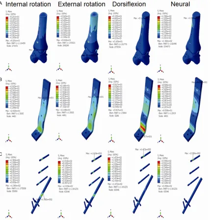
Figure 2. The stress distribution of the anterior plate ankle fusion model at the internal rotation state, the external
rotation state, the dorsiflexion state, and the neutral state. A. The stress distribution of the bone at four movement
[image:4.612.90.524.157.227.2]modes. B. The stress distribution of the plate at four movement modes. C. The stress distribution of the screw at four movement modes.
Table 4. The maximum surface displacement of four different movement modes in four fusion models
The maximum surface displacement (mm) Internal rotation(Torque) rotation External (Torque) (Bending moment)Dorsiflexion Neural mode (Vertical)
The anterior plate ankle fusion model 1.6 0.33 2.07 0.37
The anterior plate plus posterolateral screw ankle fusion model 0.18* 0.16* 0.17* 0.38*
The lateral plate ankle fusion model 0.24 1.4 0.45 0.48
The lateral plus posterolateral screw plate ankle fusion model 0.16# 0.16# 0.23# 0.49#
Note: The anterior plate ankle fusion model VS The anterior plate plus posterolateral screw ankle fusion model, *P<0.05. The lateral plate ankle fusion model VS The
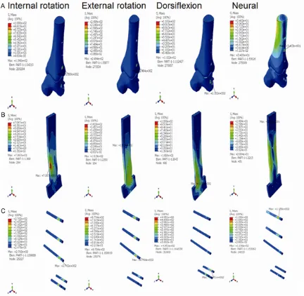
[image:4.612.93.521.267.655.2]bone, plate and screw were assessed. The stress distribution of bone, plate and screw in the anterior plate ankle fusion model was shown in Figure 2, that in the anterior plate plus posterolateral screw ankle fusion model was shown in Figure 3, that in the lateral plate ankle fusion model was shown in Figure 4, and that in the lateral plate plus posterolateral screw ankle fusion model was shown in Figure 5.
The stress peak of bone, plate and screw in the anterior plate ankle fusion model and the ante-rior plate plus posterolateral screw ankle fusion model was listed in Table 5. The stress peak of bone, plate and screw in the anterior plate plus posterolateral screw ankle fusion model was
significantly decreased at the internal rotation
state, the external rotation state and the
dorsi-flexion state (P<0.05), but not at the neural
[image:5.612.95.525.74.522.2]state. Similarly, as shown in Table 6, the stress
Figure 3. The stress distribution of the anterior plate plus posterolateral screw ankle fusion model at the internal
rotation state, the external rotation state, the dorsiflexion state, and the neutral state. A. The stress distribution of
peak of bone, plate and screw in the lateral plate plus posterolateral screw ankle fusion
model was significantly reduced than that in
the lateral plate ankle fusion model at the inter-nal rotation state, the exterinter-nal rotation state
and the dorsiflexion state, respectively (P< 0.05). No significant difference was found at
the neural state. Together, these results sug-gest that the anterior/lateral plate plus pos-terolateral screw ankle fusion models have bet-ter fusion safety.
Discussion
The finite element analysis technique was first used in the field of orthopedic surgery in 1972 [24] and has been widely used in the field of
orthopedics since. SpyrouLA established a
three-dimensional finite element model of the
normal ankle joint, which also included the
dis-tal tibia [25]. The finite element model has sta
[image:6.612.91.523.73.495.2]-ble mechanical properties and can be used repeatedly to simulate the complex anatomical
Figure 4. The stress distribution of the lateral plate ankle fusion model at the internal rotation state, the external
rotation state, the dorsiflexion state, and the neutral state. A. The stress distribution of the bone at four movement
structures and material properties [26-28]. It can also simulate various working conditions that cannot be achieved by traditional biome-chanical experiments [28]. In this study, the
three-dimensional finite element model of nor
-mal human ankle joint was successfully estab-lished by collecting the CT image data of nor-mal human ankle joint. The ankle joint fusion operation was simulated on this model. Four different ankle fusion models were successful-ly established, with good fusion stability and safety.
The internal fixation and the fusion surface are
two key factors of the ankle fusion, and are also
two artificial controllable factors during the
fusion process [29]. The use of screws and
intramedullary nails is to increase the fixation
strength and pressure of the fusion surface as much as possible [30]. In recent years, with the development of steel plate technology, steel
plate fixation is used in ankle fusion [31, 32]. In
the clinical practice, we observe that the fixa
[image:7.612.93.524.69.505.2]-tion effect of steel plate is better, with good sta-bility. The joint stiffness of patients can be
Figure 5. The stress distribution of the lateral plate plus posterolateral screw ankle fusion model at the internal
rotation state, the external rotation state, the dorsiflexion state, and the neutral state. A. The stress distribution of
decreased by plate fixation [33]. The external
force may induce deformation in the ankle joint surface and the degree of the deformation will affect the effect of ankle fusion [32]. It is
reported that plate plus screw fixation can sig
-nificantly increase fusion strength [34, 35]. In
the present study, the internal rotation,
exter-nal rotation, dorsiflexion and neutral movement
modes were used to simulate the external forc-es. The maximum surface displacement of the anterior/lateral plate plus posterolateral screw
ankle fusion model was significantly decreased.
Consistent with previous reports [34, 35], our results indicate that by combining plate and screws, the strength and stability of the ankle joint fusion is greatly enhanced. Meanwhile, the stress peak of the anterior/lateral plate plus posterolateral screw ankle fusion model was
significantly reduced. This suggests that the
risks of broken nails, broken plate and even stress fractures may be effectively reduced
and the safety of fixation may be greatly
improved.
This study has some limitations. First, the fibula
and surrounding soft tissue were removed in our models and their effects on the ankle
move-steel plate were simplified. Third, the effects of bone conditions on screw fixation were ignored.
Thus, there is still a certain degree of
differ-ence between the finite element model and the
real situation of the ankle joint. Further study is warranted to more realistically simulate the real situation of the ankle joint.
In conclusion, our findings demonstrate that
the anterior/lateral plate plus posterolateral screw ankle fusion model is effective and fea-sible in treatment of post-traumatic ankle arthritis.
Disclosure of conflict of interest None.
Address correspondence to: Qiang Xie, Department
of Hand and Foot Surgery, Affiliated Hospital of
Chengde Medical College, Xinya Villa, Shidongzigou Road, Shuangqiao District, Chengde 067000, P. R. China. Tel: +86-15732453648; E-mail: 554398- 579@qq.com
References
[image:8.612.89.523.98.191.2][1] Weatherall JM, Mroczek K, McLaurin T, Ding B and Tejwani N. Post-traumatic ankle arthritis.
Table 5. The stress peak of the anterior plate fusion model and the anterior plate plus posterolateral screw ankle fusion model
Stress peak
(MPa) Internal rotation(Torque) External rotation (Torque) (Bending moment)Dorsiflexion Neural mode (Vertical)
The anterior plate fusion model Bone 353.5 165.3 101 136.6
Plate 302.7 84.2 284.9 95
Screw 1309 270.9 685.1 335.4
The anterior plate plus posterolateral
screw ankle fusion model Bone 52.5
* 30.4* 51.8* 136.6
Plate 29.3* 21.5* 39.2* 95
Screw 138* 101.8* 147.2* 335.4
Note: Stress peak of bone, plate, screw in the anterior plate ankle fusion model VS that in the anterior plate plus posterolateral screw ankle fu-sion model, respectively, *P<0.05.
Table 6. The stress peak of the lateral plate fusion model and the lateral plate plus posterolateral screw ankle fusion model
Stress peak
(MPa) Internal rotation(Torque) External rotation (Torque) (Bending moment)Dorsiflexion Neural mode (Vertical)
The lateral plate fusion model Bone 109 249.4 110.2 34
Plate 70.7 161.9 105.8 28.8
Screw 270.2 879.4 495.1 115.6
The lateral plate plus posterolateral
screw ankle fusion model Bone 43.4
* 30.9* 36.5* 34.1
Plate 24.8* 16.1* 29* 29.1
Screw 107* 85.7* 129.3* 116.1
[image:8.612.88.523.261.358.2][2] Castagnini F, Pellegrini C, Perazzo L, Vannini F and Buda R. Joint sparing treatments in early ankle osteoarthritis: current procedures and future perspectives. J Exp Orthop 2016; 3: 3. [3] Popelka S, Sosna A, Vavrik P, Jahoda D, Bartak
V and Landor I. [Eleven-year experience with total ankle arthroplasty]. Acta Chir Orthop Traumatol Cech 2016; 83: 74-83.
[4] Nihal A, Gellman RE, Embil JM and Trepman E. Ankle arthrodesis. Foot Ankle Surg 2008; 14: 1-10.
[5] Abidi NA, Gruen GS and Conti SF. Ankle ar-throdesis: indications and techniques. J Am Acad Orthop Surg 2000; 8: 200-209.
[6] Haddad SL, Coetzee JC, Estok R, Fahrbach K, Banel D and Nalysnyk L. Intermediate and long-term outcomes of total ankle arthroplasty and ankle arthrodesis. A systematic review of the literature. J Bone Joint Surg Am 2007; 89: 1899-1905.
[7] Colman AB and Pomeroy GC. Transfibular an
-kle arthrodesis with rigid internal fixation: an
assessment of outcome. Foot Ankle Int 2007; 28: 303-307.
[8] Nickisch F, Avilucea FR, Beals T and Saltzman C. Open posterior approach for tibiotalar ar-throdesis. Foot Ankle Clin 2011; 16: 103-114. [9] Torudom Y. The results of ankle arthrodesis
with screws for end stage ankle arthrosis. J Med Assoc Thai 2010; 93 Suppl 2: S50-54. [10] Clare MP and Sanders RW. The anatomic
com-pression arthrodesis technique with anterior plate augmentation for ankle arthrodesis. Foot Ankle Clin 2011; 16: 91-101.
[11] Yasui Y, Takao M, Miyamoto W, Innami K, Kom-atsu F, Narita N and MKom-atsushita T. Technique tip: open ankle athrodesis using locking com-pression plate combined with anterior sliding bone graft. Foot Ankle Int 2010; 31: 1125-1128.
[12] Gessmann J, Ozokyay L, Fehmer T, Muhr G and Seybold D. [Arthrodesis of the infected ankle
joint: results with the Ilizarov external fixator]. Z
Orthop Unfall 2011; 149: 212-218.
[13] Latt LD, Glisson RR, Adams SB Jr, Schuh R, Narron JA and Easley ME. Biomechanical
com-parison of external fixation and compression
screws for transverse tarsal joint arthrodesis. Foot Ankle Int 2015; 36: 1235-1242.
[14] Holt ES, Hansen ST, Mayo KA and Sangeorzan
BJ. Ankle arthrodesis using internal screw fixa -tion. Clin Orthop Relat Res 1991; 21-28. [15] Ogilvie-Harris DJ, Fitsialos D and Hedman TP.
Arthrodesis of the ankle. A comparison of two
versus three screw fixation in a crossed con
-figuration. Clin Orthop Relat Res 1994;
195-199.
[16] Mitchell PM, Douleh DG and Thomson AB. Comparison of ankle fusion rates with and
without anterior plate augmentation. Foot An-kle Int 2017; 38: 419-423.
[17] Kakarala G and Rajan DT. Comparative study
of ankle arthrodesis using cross screw fixation
versus anterior contoured plate plus cross
screw fixation. Acta Orthop Belg 2006; 72:
716-721.
[18] Gui ZS, Xu XF and Li HY. Comparison of head-less compression screw and interlocking
com-pression plate fixation in ankle fusion. Zhong
Guo Zu Zhi Gong Cheng Yan Jiu 2016; 20: 4623-4629.
[19] Xiong LP and Zhang SM. Technique and short-term results of ankle arthrodesis using anteri-or plating. Orthopedic Journal of China 2010; 18: 2055.
[20] Schuberth JM, Ruch JA and Hansen ST Jr. The
tripod fixation technique for ankle arthrodesis.
J Foot Ankle Surg 2009; 48: 93-96.
[21] Lu CH, Yu B, Chen HQ and Lin QR. Establish-ment and stress analysis of three-dimensional
finite element model of talus in normal gait
Nan Fang Yi Ke Da Xue Xue Bao 2011; 2273-2276.
[22] Clifford C, Berg S, McCann K and Hutchinson
B. A biomechanical comparison of internal fixa -tion techniques for ankle arthrodesis. J Foot Ankle Surg 2015; 54: 188-191.
[23] Yasui Y, Hannon CP, Seow D and Kennedy JG. Ankle arthrodesis: a systematic approach and review of the literature. World J Orthop 2016; 7: 700-708.
[24] Huiskes R and Chao EY. A survey of finite ele -ment analysis in orthopedic biomechanics: the
first decade. J Biomech 1983; 16: 385-409.
[25] Spyrou LA and Aravas N. Muscle-driven finite
element simulation of human foot movements. Comput Methods Biomech Biomed Engin 2012; 15: 925-934.
[26] Vazquez AA, Lauge-Pedersen H, Lidgren L and Taylor M. Finite element analysis of the initial
stability of ankle arthrodesis with internal fixa
-tion: flat cut versus intact joint contours. Clin
Biomech (Bristol, Avon) 2003; 18: 244-253. [27] de Leeuw PA, Hendrickx RP, van Dijk CN,
Stufkens SS and Kerkhoffs GM. Midterm re-sults of posterior arthroscopic ankle fusion. Knee Surg Sports Traumatol Arthrosc 2016; 24: 1326-1331.
[28] Wang Y, Li Z, Wong DW and Zhang M. Effects of ankle arthrodesis on biomechanical perfor-mance of the entire foot. PLoS One 2015; 10: e0134340.
[29] Rabinovich RV, Haleem AM and Rozbruch SR. Complex ankle arthrodesis: review of the litera-ture. World J Orthop 2015; 6: 602-613. [30] Zhang C, Shi Z and Mei G. Locking plate versus
-talocalcaneal arthrodesis: a retrospective analysis. Indian J Orthop 2015; 49: 227-232. [31] Zwipp H. Arthrodesis of the ankle. Acta Chir
Or-thop Traumatol Cech 2017; 84: 13-23. [32] Slater GL, Sayres SC and O’Malley MJ. Anterior
ankle arthrodesis. World J Orthop 2014; 5: 1-5.
[33] Chen ZB, Hong GX and Wang FB. Upper limb function assessment table. Zhong Guo Xiu Fu Chong Jian Wai Ke Za Zhi 2004; 18: 520-521. [34] Ahmad J, Pour AE and Raikin SM. The modified
use of a proximal humeral locking plate for tib-iotalocalcaneal arthrodesis. Foot Ankle Int 2007; 28: 977-983.
[35] Mueckley TM, Eichorn S, von Oldenburg G, Speitling A, DiCicco JD 3rd, Hofmann GO and Buhren V. Biomechanical evaluation of primary stiffness of tibiotalar arthrodesis with an