Volume 2010, Article ID 307983,13pages doi:10.1155/2010/307983
Research Article
Packet Format Design and Decision Directed Tracking Methods
for Filter Bank Multicarrier Systems
Peiman Amini and Behrouz Farhang-Boroujeny
The Electrical and Computer Engineering Department, University of Utah, UT 84112, USA
Correspondence should be addressed to Behrouz Farhang-Boroujeny,[email protected]
Received 11 May 2009; Revised 29 September 2009; Accepted 28 December 2009
Academic Editor: Pierre Siohan
Copyright © 2010 P. Amini and B. Farhang-Boroujeny. This is an open access article distributed under the Creative Commons Attribution License, which permits unrestricted use, distribution, and reproduction in any medium, provided the original work is properly cited.
Packetized data transmission is commonly used in wireless communication systems. Each packet starts with a preamble which is used to synchronize the receiver with carrier frequency of the incoming signal, to find a good timing phase, and to identify the channel impulse response or to adjust a set of channel equalizer parameters. In this paper, following the same philosophy, we develop a packet format for multicarrier systems that operate based on filter banks, filter bank multicarrier (FBMC) systems. The related algorithms for carrier frequency and timing recovery as well as channel identification/equalizer adjustment and methods for carrier and timing tracking loops are proposed. The proposed ideas are evaluated and their satisfactory performance are presented through computer simulations.
1. Introduction
Multicarrier modulation has been recognized as the most promising approach for practical and efficient realization of broadband communication systems. Among various multi-carrier modulation methods, orthogonal frequency division multiplexing (OFDM), [1], is the most widely adopted method in the current standards. While OFDM may be a good choice for point-to-point communication, it may not be the best choice in many other applications. For instance, in the up-link of an orthogonal frequency division multiple access (OFDMA) network, the loss of synchronization between the carriers of different nodes will result in a significant performance loss and often complex processing steps have to be adopted at the base station to recover this loss (partially); see [2] and the references therein. Such complex processing can be avoided by adopting alternative methods that use filter banks for multicarrier modulation. OFDMA limitation is the result of the fact that the side-lobes (equiv-alent to stopband) of the filters based on which OFDMA signals are constructed are relatively large. In filter bank multicarrier (FBMC) methods, this problem is resolved, simply, by using filters with well-attenuated stopbands, [3].
It is also interesting to note that the researchers who have studied filter banks, mostly, for signal compression applications, have invented a class of filter banks which are called modified DFT (MDFT) filter bank, [22]. Careful study of MDFT reveals that this is in fact a reinvention of Saltzberg’s filter bank, extended and formulated in discrete-time, and applied to compression/coding. The literature on MDFT begins with the pioneering works of Fliege, [23], and later has been extended by others, for example, [24–27].
Successful implementation of any communication sys-tem, including multicarrier systems, requires mechanisms for carrier and timing acquisition and tracking. Moreover, in packetized data, each packet is equipped with a preamble that is specifically designed to facilitate fast tuning of carrier frequency and timing phase at the receiver, upon the receipt of each packet. In OFDM-based systems, such as IEEE 802.11a, g and 802.16e, the preamble consists of two parts: a short preamble followed by a long one [28, 29]. The short preamble is constructed by adding a few well-separated tones to allow a coarse acquisition of carrier frequency offset (CFO), with a wide lock range. The short preamble is also used to adjust the gain of an (automatic gain control) AGC at the receiver input. The long preamble consists of a cyclic prefix followed by two full cycles of an OFDM symbol. This can be used for fine tuning of the carrier frequency and adjustment of the timing phase as well as the frequency domain equalizers [30,31].
This paper borrows the ideas of short and long preambles from the OFDM standards/literature and extends them to the FBMC systems. In the OFDM standards, for example, IEEE 802.11a, g and 802.16e, the short preamble consists of a few cycles of a periodic signal. The presence of a frequency offset introduces a constant phase rotation in successive periods of such periodic signals. This phase rotation can be easily detected using a standard correlation technique, and accord-ingly the value of the frequency offset is detected. In addition, the periodic structure of the short preamble simplifies its detection and thus detection of the beginning of each packet. Moreover, the short preamble power level is measured and used to adjust an AGC for the rest of the packet. Since these steps are performed independent of the processing of the rest of the packet, the short preamble can be applied to any packetized signal including an FBMC packet. Hence, in this paper, we propose to use a short preamble similar to those in OFDM packets for FBMC systems [32,33].
The long preamble used in the OFDM systems, on the other hand, is not applicable to the FBMC systems. The presence of cyclic prefix in OFDM isolates successive symbol frames and also allows some tolerance with respect to timing phase offset. In the FBMC systems, the extended length of the subcarrier filters (equivalently, the prototype filter) results in significant overlap of successive symbol frames. Moreover, because of the absence of any guard interval between successive symbol frames, the timing phase in FBMC system cannot tolerate any significant offset. To deal with these issues, we propose to use a long preamble which is isolated from the short preamble and also from the payload of the packet. This is done by adding sufficient guard time/null space after the short preamble and before
the payload. More detail of the proposed packet format is presented inSection 3.
After an initial tuning of carrier frequency and timing phase, tracking algorithms should be used to make sure that the receiver remains locked to the rest of the incoming packet. This paper, thus, also proceeds with development of decision directed algorithms for carrier and timing tracking. The satisfactory performance and robustness of the developed algorithms are studied through computer simulations.
In the past, a number of authors have looked into the problem of carrier and timing synchronization in FBMC communication systems, [34–43]. However, the approaches taken in these studies are different from the work presented in this paper. While we use pilot symbols (preambles) for carrier and timing acquisitions, most of the past works operate based on the statistical properties of the FBMC signals, that is, they are blind methods. B¨olsckei was the first to propose a blind carrier offset and timing estimation method for the Saltzberg’s FBMC method [34]. It relies on the second-order statistics and cyclostationarity of the modulated signals. Also, [34] acknowledges that when all subcarrier channels carry the same amount of power, the (unconjugate) correlation function of multicarrier signals vanishes to zero and thus proposes unequal subcarrier powers (subcarrier weighting) to enable the proposed syn-chronization methods. Noting this, Ciblat and Serpedin have developed a carrier acquisition/tracking method using the conjugate correlation function of FBMC signals which they found exhibits conjugate cyclic frequencies at twice the CFO [35]. Fusco and Tanda [36] have taken advantage of both the conjugate and unconjugate cyclostationarity of Saltzberg’s multicarrier signals to derive a maximum likelihood CFO estimator. Other related works can be found in [37–45]. An exception to the above works is [46] where the authors propose a synchronization method that uses a known periodic pilot signal, similar to the short preamble in IEEE 802.11a and g, and IEEE 802.16e, [28,29]. Also, more recently, Fusco et al. [47] have proposed a pilot signal similar to the long preamble proposed in this paper. Fusco et al. [47] use this pilot signal for timing recovery and carrier phase estimation, based on a cost function which is different from the one proposed in this paper. Simulation results that compare the accuracy of the timing recovery method of [47] with the one proposed in this paper are presented in
Section 9. To the best of our knowledge there is no report of any synchronization method for the Chang’s multicarrier technique.
fb/2
· · ·
f
(a) fb
· · ·
f
(b) fb
· · ·
f (1 +α)fb
(c)
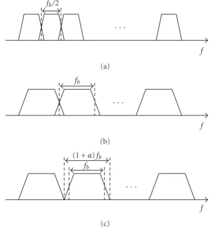
Figure1: Sample spectra of various FBMC methods. (a) CMT. (b) SMT. (c) FMT.
packet format and associated acquisition and tracking algo-rithms are presented inSection 9. The concluding remarks are made inSection 10.
2. Review of Filter Bank Multicarrier Methods
Beside CMT, and SMT, there is one more FBMC method that has been well studied in the literature. This method, which is called filtered multitone (FMT), was originally developed for digital subscriber line (DSL) channels as a means of avoiding interference with the HAM radio channels, [50–52]. Application of FMT to wireless channels has also been considered recently, for example, [3,53–55]. FMT follows the principles of the conventional frequency division multiplexing, where the subcarrier band channels are nonoverlapping. Hence, a guard band is inserted between each pair of adjacent subcarrier channels to allow a transition from passband to stopband. Consequently, FMT is less band efficient than CMT and SMT.
Figure 1presents a set of typical spectra of FMT, CMT and SMT signals. To allow comparison of different cases, the bandwidth of each subcarrier channel is marked in terms of the symbol/baud rate fb = 1/T, whereT is the symbol interval. As seen, while in the case of SMT each subcarrier band, effectively, occupies a width of fb, this reduces to fb/2 in the case of CMT. In the case of FMT, to keep subcarrier bands nonoverlapping, an excess bandwidth ofα×100% is allowed. Although the emphasis of this paper is on CMT and SMT, many of the results developed are applicable to FMT as well. Particularly, the packet format that is introduced in the next section is readily applicable to FMT.
Figures 2and 3present the block diagrams of a CMT transceiver and an SMT transceiver, respectively. In the case of CMT, the VSB modulation is established through a set of
s0(t)
h(t)ej2πTt
s1(t)
h(t)ej2πTt
sN−1(t)
h(t)ej2πTt
. . .
ejπTt+π2
ej(N−1)πTt+π2
Modulation to RF band ej2π fct
{·}
x(t) To channel
(a) From channel
y(t) e−j2π fct
Demodulation from RF band
e−jπTt+π2
e−j(N−1)πTt+π2
h(t)ej2πTt
h(t)ej2πTt
h(t)ej2πTt
. . .
{·}
{·}
{·} s0[n]
s1[n]
sN−1[n] (b)
Figure2: Block diagram of a CMT transceiver.
VSB filters at baseband, using the VSB filterh(t)ej(π/2T), and then modulating their outputs to the respective subcarrier bands. Here, h(t) is a square-root Nyquist filter with the bandwidth of fb/2. Also, in Figure 2, h(t) = h(−t) is the matched pair of h(t). The intercarrier interference (ICI) among adjacent subcarrier channels is conveniently cancelled by choosingh(t) to be an even symmetric function of time, that is, h(t) = h(−t) = h(t). The presence of a phase differenceπ/2 between adjacent subcarriers also plays an important role in ICI cancellation. For more details on CMT, the reader may refer to the original work of Chang [4]. In the case of SMT, h(t) is a square-root Nyquist filter with the bandwidth of fb. Also, the quadrature subcarrier channels are time shifted byT/2 with respect to the in-phase subcarrier channels. Similar to CMT, in SMT also ICI among adjacent channels is conveniently cancelled by choosingh(t) to be an even symmetric function of time, and thush(t) = h(t), [5].
3. Packet Format
sI0(t)
jsQ0(t)
sI1(t)
jsQ1(t)
sI N−1(t)
jsQN−1(t) h(t)
ht−T
2
h(t)
ht−T
2
h(t)
ht−T
2 . . .
ej2Tπt+π2
ej(N−1)2Tπ+π2
Modulation to RF band
ej2π fct
{·}
x(t) To channel
(a)
From channel y(t) e−j2π fct
Demodulation from RF band
e−j2Tπt+π2
e−j(N−1)2Tπt+π2
{·}
{·}
{·}
{·}
{·}
{·} h(t) ht+T2
h(t) ht+T2
h(t) ht+T2
. . .
sI
0[n] sQ0[n]
sI
1[n] sQ1[n]
sI
N−1[n] sQN−1[n] T (b)
Figure3: Block diagram of a SMT transceiver.
12 tones at the subcarrier numbers{−24,−20,−16,−12,−8,
−4, 4, 8, 12, 16, 20, 24}. We may also recall that the active data and pilot subcarriers in IEEE 802.11a are numbered −26 through 26, excluding 0. The long training (preamble) starts with a guard interval (a cyclic prefix), GI2, followed by two cycles of a known OFDM symbol,T1 andT2. By the end of the long training, all synchronization steps (carrier tuning and timing recovery) have to be completed and the receiver should be ready to correctly detect the payload part of the packet. The payload begins with an OFDM symbol called signal field which contains information such as the length of the payload, the data rate and the channel code.
Following the same idea as in IEEE 802.11a, we propose the packet format shown in Figure 5. The short training (preamble) remains the same as the one inFigure 4. The long training (preamble) is an isolated FBMC symbol which is positioned such that the transients of the underlying filters
do not overlap with the short training and the payload parts of the packet. In other words, the length of the long training should be at least equal to the length of the prototype filter h(t). (We note that since a matched filterh(t) is applied at the input of the receiver, strictly speaking, the length of the long preamble after filtering at the receiver is at least twice the duration ofh(t). However, since the tails of the response at the beginning and end are small, we found, numerically, restricting the length of the long preamble to the length h(t) does not incur any significant loss in performance). We note that, in practice, when the available bandwidth to both OFDM and FBMC system is the same, the length of h(t) is typically equivalent to 6 OFDM symbols; see the design examples in [56]. It thus may appear that with the proposed preamble, FBMC is less bandwidth efficient than OFDM. However, the absence of guard intervals (cyclic prefix) in FBMC will result in a shorter payload and, thus, the overall packet length in an FBMC system is expected to be significantly shorter than its counterpart in OFDM.
4. Carrier Acquisition
As in IEEE 802.11a, we use the short training part of the preamble for setting the AGC gain and a coarse acquisition of the carrier frequency. Since this has been well studied and reported in the literature, for example, [57,58], here, we concentrate on the design of the long training and its application to fine tuning of the carrier frequency.
As long training, we use a single frame of binary phase shift keying multicarrier signal, that is, defined as
xlong(t)=
(N/2)−1
k=0
akh(t)ej(4kπ/T)t, (1)
whereaks are a set of binary numbers with magnitudeK; that is, they take values of±K. We may chooseaks to optimize certain properties of xlong(t). For instance, to minimize its peak to average power ratio (PAPR). This optimization is of particular interest as it will allow maximization of signal power during the training phase which, in turn, improve the accuracy of the carrier frequency and timing phase estimates. Assuming the channel has an equivalent baseband impulse response c(t), the long training symbol will be received as
ylong(t)=xlong(t)c(t) +v(t), (2)
wherev(t) is the channel additive noise. Taking the Fourier transform on both sides of (2) and using (1), we obtain
Ylongf=Af+Vf, (3)
where
Af=
(N/2)−1
k=0 akC
fH
f −2k
T
Short training (8μs) Long training (8μs)
Signal field
(4μs) Data
t1 t2 t3 t4 t5 t6t7 t8 t9t10 GI2 T1 T2 GI Signal GI Data1 GI Data2 · · ·
Figure4: Packet format in IEEE 802.11a.
Short training Long training
Signal
field Data
t1 t2 t3 t4 t5t6 t7 t8 t9t10 Signal Data1 Data2 · · ·
Optimum timing phase (center of the long training)
Figure5: The proposed packet format for FBMC systems.
Squaring both sides of (3), we get
Ylong
f 2= Af 2+ Vf 2+ 2RA∗fVf. (5)
Assuming a low noise channel, one may ignore the term
|V(f)|2
on the right-hand side and thus simplify (5) to
Ylong
f 2= Af 2+ 2RA∗fVf. (6)
Assuming that the channel noise,v(t), is a complex symmet-ric white stationary Gaussian process with an instantaneous variance ofσ2
v,V(f) also will be a complex-valued symmet-ric white stationary Gaussian process with an instantaneous variance ofσ2
v. Hence,R{A∗(f)V(f)}will be a real-valued white nonstationary Gaussian process with an instantaneous variance|A(f)|2σ2
v/2 and, accordingly, (6) may be rewritten as
Ylong
f 2= Af 2+ Af Vf, (7)
where V(f) is a real-valued white stationary Gaussian process with an instantaneous varianceσ2
v=2σv2.
Equation (7) corresponds to the case where there is no carrier offset between the transmitter and receiver. In presence of a carrier frequency offsetΔfc, (7) converts to
Ylong
f 2= Af −Δfc 2+ A
f −Δfc V
f (8)
or, alternatively,
Ylong f 2 A
f −Δfc = A
f −Δfc +V
f. (9)
SinceV(f) is a white noise, a maximum likelihood (ML) estimate ofΔfc, sayΔfc, may be obtained by minimizing the following cost function
ζΔfc=
∞
−∞
⎛ ⎜ ⎝
Ylong f 2 A
f −Δfc − A
f −Δfc ⎞ ⎟ ⎠ 2
df
=
∞
−∞
1
A
f −Δfc 2
× Ylongf 2− Af −Δfc 2 2
df .
(10)
This integral, unfortunately, becomes problematic for values of f where|A(f)|is small. When|A(f)|is small, the term
|V(f)|2
that was ignored in the equations following (5), will become significant and thus may not be ignored. To deal with this situation, we suggest the following modification to (10). The integral is performed over ranges of f where |A(f)|
is above a certain threshold. Finding an optimum value of this threshold, however, is not a straightforward task. On the other hand, as will be shown inSection 9, other alternative cost functions that are introduced below, may prove more useful in practice.
If we simply ignore the scaling factor 1/|A(f −Δfc)|2 under the integral (10), we obtain the modified/simplified cost function
ξΔfc=
∞
−∞ Ylong
f 2− Af −Δfc 2 2
df .
(11)
The minimization ofξ(Δfc) can be reformulated as
Δfc=arg max
Δfc
∞
−∞
Ylong
f 2 Af −Δfc 2df . (12)
channel, C(f), that we also wish to estimate as part of the receiver initialization. In the numerical results presented in Section 9, we assume C(f) is known when minimizing ζ(Δfc). However, as practical estimators, we concentrate on (12), and when using this estimator, we simplify the problem by considering the following approximations.
(1) We ignore the channel effect and simply assume that C(f)= 1, that is, an ideal channel. Noting that the termsH(f −(2k/T)) are nonoverlapping, this leads to
A
f 2=K2 (N/2)−1
k=0 H
f −2k
T
2. (13)
(2) We note that when channel noise is small,|Ylong(f)|2 resembles the shape of |A(f −Δfc)|2 accurately and, thus,|Ylong(f)|2 may be used to estimate the magnitude of C(f) at each of the bands defined by the terms H(f −(2k/T)) and, accordingly, an approximation to|A(f)|2
, may be constructed as
A
f 2=K2 (N/2)−1
k=0
|Ck|2 H
f −2k
T
2, (14)
whereCk=Ylong(2k/T) is an estimate ofC(f) atf = (2k/T).
5. Timing Acquisition
Once the CFO, Δfc, is estimated and the long training preamble is compensated accordingly, the optimum timing phase is estimated by taking the following steps. The CFO-compensated long training is passed through an analysis filter bank that extracts the transmitted training symbols aks. Recalling that the long training consists of a number of isolated subcarrier symbols across both time and frequency, we note that, in the absence of channel distortion, at the optimum timing phase, the analyzed subcarrier signals reach their maximum amplitudes independent of one another. The presence of channel introduces some distortion in the signal such that the optimum timing phase may not be the same for different subcarriers. It is thus reasonable to check the energy of the analyzed signals and choose the timing phase that maximizes the total energy of demodulated signals across all the subcarriers.
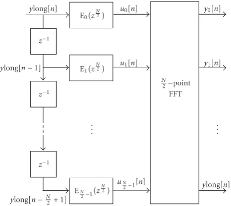
Figure 6presents the signal analyzer that we propose for timing acquisition. It is a polyphase filter bank with N/2 bands, withE0(z) through E(N/2)−1(z) being the polyphase components of the prototype filter h[n]; a discrete-time version ofh(t). The input ylong[n] is a sampled version of
ylong(t). The optimum timing phase is, thus, obtained as
nopt=arg max n
(N/2)−1
k=0
yk[n] 2
. (15)
ylong[n]
z−1
ylong[n−1] z−1
z−1
ylongn−N
2 + 1
E0z
N
2
E1
zN2
EN
2−1
zN2
u0[n]
u1[n]
uN
2−1[n]
. . .
N
2−point FFT
y0[n]
y1[n]
ylong[n] . . .
Figure6: The signal analyzer for timing acquisition.
Using the Parseval’s theorem for DFT, (15) may equivalently be written as
nopt=arg max n
(N/2)−1
k=0
|uk[n]|2, (16)
where uk[n] are the signal samples at the FFT input in
Figure 6. This shows that the optimum timing phase can be obtained without performing any FFT operation.
In a recent work Fusco et al. [47] have also proposed the use of an isolated FBMC symbol (similar to the proposed long preamble in this paper) for timing acquisition. They have noted that in the absence of channel distortion, such a symbol is symmetric with respect to its center and have developed the following equation for timing acquisition:
nopt=arg max n
(M−1)/2
i=1
ylong[n−i]ylong[n+i]
(17)
whereMis the length ofylong[n]. It is also noted in [47] that the symmetry property of the isolated FBMC symbol holds approximately in the presence of channel and, thus, argued that the same formula may be used for timing acquisition in multipath/frequency selective channels.
It is also worth noting that while in the absence of the channels distortion, both (16) and (17) provide the optimum timing phase, they only result in a near optimum timing phase when a channel distortion and/or noise present. We evaluate the accuracy of the two methods and compare them with each other inSection 9.
6. Equalization
Once the preamble is CFO-compensated, and the optimum timing phase is acquired, assuming a flat gain over each subcarrier channel, the outputs of the signal analyzer of
y[n]
e−j
Analysis filter bank
Loop filter
sk[n]s
ϕ[n]
Slicer
Phase estimator
¯ sk[n]s
Figure7: A PLL equipped FBMC receiver. The inputy[n] is the demodulated received signal.
gains at the center frequencies 2k/T,k=0, 1,. . ., (N/2)−1. Moreover, if we assume that these samples are dense enough, an interpolation may be applied to find the channel gains at all frequency points where the payload subcarrier channels will be located. Note that the locations of the center of subcarrier channels depend on the modulation type, say, being CMT or SMT. Once the channel gains are obtained, one may choose to use a single-tap complex equalizer per subcarrier channel. In that case, the gains of the equalizers are the inverse of the channel gains at the center frequency of each subcarrier channel. It is also possible to use a multitap equalizer per subcarrier. This has been discussed in detail in [8], for SMT, where it is argued that to remove ICI, the equalizers should be fractionally spaced. The receiver structure proposed in [8] is tailored towards implementation of the half-symbol spaced fractionally spaced equalizers.
In the case of CMT, the equalizers shall be inserted at the points before theR{·}blocks in Figure 2(b). The efficient CMT implementations proposed in [21,48] provide access to these points and thus equalizers can be easily implemented.
In the case of SMT, if one follows an implementation that mimics the receiver structure ofFigure 3, the equalizers should be inserted at the points right before where the demodulated signals branch to theR{·}andI{·} blocks. If that is the case and decision directed loops are adopted for the equalizers tracking, the presence of the filters h(t) andh(t+T/2) within the loops will introduce some delay which may result in an undesirable behavior. Fortunately, in the case SMT also the efficient polyphase structures that have been proposed in the literature, for example, [8], are such that theR{·}andI{·}blocks are moved to the output of the filtersh(t) andh(t+T/2) and thus avoid the problem of loop delay.
7. Carrier Tracking
In this section, we describe a carrier tracking method which may be used to track any residual carrier offset during the payload transmission of an FBMC data packet. We make the reasonable assumption that the payload starts with an accurate estimate of the carrier phase. However, without any carrier tracking loop, the carrier phase may drift over the
length of the payload. Hence, the goal is to design a phase-locked loop (PLL) that forces any built up phase error to zero. Because of their differences, we treat SMT and CMT separately.
7.1. SMT. In an SMT receiver, the phase and quadrature components of the detected data symbols, before passing through a decision device (a slicer), are given by
sI
k[n]=
∞
l=−∞
N−1
m=0
∞
−∞
sI
m[l]h(τ−lT)h(τ−nT)
×cos
(m−k)
2πτ T + π 2
+ϕ[n]
−sQ m[l]h
τ−lT−T
2
h(τ−nT)
×sin
(m−k)
2πτ T + π 2
+ϕ[n]
dτ
sQk[n]=
∞
l=−∞
N−1
m=0
∞
−∞
sIm[l]h(τ−lT)h
τ+T
2 −nT
×sin
(m−k)
2πτ T + π 2
+ϕ[n] +πΔfcT
+sQ m[l]h
τ−lT+T
2
×h
τ+T
2 −nT
×cos
(m−k)
2πτ T + π 2
+ϕ[n] +πΔfcT
dτ, (18)
where ϕ[n] is the demodulator carrier phase angle at time nT. Combining (18) and separating the desired and interference terms, we obtain
sk[n]=sIk[n] +js Q k[n]
=sI k[n]
∞
−∞h
2(τ) cosϕ[n]dτ+jsQ k[n]
×
∞
−∞h
2(τ) sinϕ[n] +πΔf cT
dτ+ιk[n] (19)
where ιk[n] is the interference resulting from ISI and ICI terms. Although, for brevity, the channel noise is not included in (18), one can argue thatιk[n] may include the channel noise as well.
∞
−∞h2(τ)dτ = 1 since h(t) is a root-Nyquist filter, (19)
reduces to
sk[n]≈sk[n]ejϕ[n]+ιk[n], fork=0, 1,. . .,N−1. (20)
The goal of the carrier tracking loop is to forceϕ[n] to zero. We assume a receiver structure as inFigure 7. We obtain an averaged estimate of the phase errorϕ[n] as
ϕ[n]=∠
⎛ ⎝N−1
k=0
s∗k[n]sk[n] ⎞
⎠ (21)
wheresk[n] is the detected data symbol after passingsk[n] through a slicer and∠(x) denotes the angle associated with the complex variablex. The loop filter output is an estimate of the phase error iny[n] arising from the CFO.
7.2. CMT. FollowingFigure 2and assuming a phase error ϕ[n] at the analysis filter bank input, if we switch theR[·] blocks and the sampler, one finds that the input to theR[·] block at thekth subcarrier channel is given by
sC
k[n]=ejϕ[n] N−1
m=0 +∞
l=−∞
∞
−∞sm[l]h(τ−lT)h(τ−nT)
×ej(π/2T)(nT−lT)ej(m−k)((π/T)τ+(π/2))dτ, (22)
where the superscript “C” onsC
k[n] is to emphasize that it is complex-valued.
Separating the terms associated with the desired symbol, sk[n], and the interference terms in (22) and noting that
∞
−∞h2(τ)dτ=1, we obtain
sC
k[n]≈sk[n]ejϕ[n]+ιk[n], fork=0, 1,. . .,N−1, (23)
where, as in the case of SMT,ιk[n] is the interference resulting from ISI and ICI terms as well as channel noise. Also, following the same line of thoughts as in the case of SMT, one finds that the PLL structure presented in Figure 7 is applicable to CMT as well, with (21) replaced by
ϕ[n]=∠
⎛ ⎝N−1
k=0
sk[n]sCk[n] ⎞
⎠ (24)
where s[n] is obtained by passing the real part of sC k[n] through an slicer.
Although (21) and (24) look similar and thus one may expect the same behavior of the associated PLLs, there is a difference that should be noted. In the steady-state, when ϕ[n] is small, (21) provides a much less noisy estimate of ϕ[n] as compared to (24). This difference arises because of the following reasons. In SMT, the phase and quadrature components of each recovered symbol are sampled when there is negligible amount of ISI and ICI. On the other hand, in CMT, although at correct sampling time the real part of
sCk[n] may be free of ISI and ICI, its imaginary part contains a significant level of ISI and ICI. When the carrier phase is known, the imaginary part of sCk[n] is simply ignored and thus has no impact on the decision valuesk[n]. However, the relatively large variance of the imaginary part ofsCk[n] results in a noisy estimate ofϕ[n]. Nevertheless, in systems with the packet format proposed in this paper, we have numerically found that since the preamble allows a very good estimate of CFO, to track the residual CFO, in the PLL, one may use a loop filter with a sufficiently small gain for suppression of the noisy component ofϕ[n].
8. Timing Tracking
In an OFDM system, the timing offset can be as long as the length of CP minus the length of the channel impulse response without any detrimental effect. In an FBMC system, on the other hand, any timing offset results in ISI and ICI. Hence, timing tracking is an important issue in FBMC systems and has to be given due attention. Furthermore, we note that in standards such as 802.11n, aggregation is used on data packets to make the system more bandwidth efficient. As a result, longer packet lengths are being transmitted, which in turn mandates timing tracking algorithms.
Assuming that, a timing phase offset value κ, can be adjusted before the analysis filter bank, one may define the cost function
Υ[n,κ]=
N−1
m=0
sm[n,κ]−sm[n,κ] 2, (25)
wheresm[n,κ] is the detected symbol at the output of themth subcarrier channel, at timen, when the timing offset value areκandsm[n,κ] is obtained after passingsm[n,κ] through a slicer. The optimum timing offset is thus tracked by searching for a value ofκthat minimizesΥ[n,κ]. A typical early-late gate timing recovery method, [59,60], may be adopted for this purpose.
9. Simulation Results
In this section, the performance of the proposed packet format is evaluated through a set of numerical tests. We consider a random sampled channel with delay-power profile
ρ[n]=e−0.85n, forn=0, 1, 2,. . ., 15, (26)
We use a short preamble similar to that of IEEE 802.11a and g in our packets, that is, 10 cycles of a periodic signal with period of 0.8μs. The long preamble is an isolated SMT symbol in which the even subcarriers are filled up by a set of binary phase-shift keying (not QAM, OQAM or VSB) symbols, and the odd subcarrier are filled up with zeros, as in (1). The binary symbolsakare selected through a random search to minimize the peak power ofxlong(t). This combined with the fact aks are nonzero only at even subcarriers will allow us to reduce the peak amplitude ofxlong(t) to about 9 dB below that of the payload, assuming that the pilot symbols ak have the same power as the payload symbolssk[n]. We add this margin of 9 dB to xlong(t) and transmit a high-powered long preamble. Since this boosts the SNR of the long preamble, it leads to a more accurate carrier estimation and timing acquisition. To allow reproduction of the results presented here by an interested reader, we note that the samples ofxlong(t), at the ratefs=4N/T, are generated using the following instructions in MATLAB:
N=64; L=4∗N; K=6; alpha=1; gamma=1;
h=sr Nyquist p(K∗L,L,alpha,gamma);
a=sign(randn(N/2,1));
xlong=H∗a;
where sr Nyquist p(N,M,alpha,gamma) is a square-root Nyquist filter design program that has been developed in [61] and can be downloaded from the second author’s website:
http://www.ece.utah.edu/∼farhang/. The designed filterh[n] has a length ofKL+ 1 andh[n]h[n] has zero crossings at an intervalLsamples. Also, in the above MATLAB lines, “H” is a (KL+ 1)×(N/2) matrix with thekth column of
hk=
h[0]h[1]ej4π(k/L)· · ·h[n]
×ej4π(k/L)n· · ·h[KL]ej4π(k/L)KLT, k=0, 1,. . .,N 2. (27)
The SNR is defined for the payload portion of each packet, that is, it is defined as the ratio of payload power over the noise variance. Also, a random carrier offset Δfc is added to each packet. This random offset is from a uniform distribution in the range [−0.4Δfshort, +0.4Δfshort], where
Δfshortis the spacing between the tones in the short preamble.
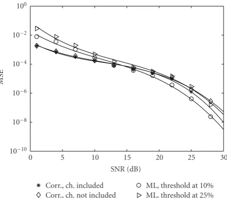
Figure 8presents the mean square error (MSE) of the residual CFO (normalized to the carrier spacing) after tuning the carrier using the long preamble. The three methods discussed in Section 4 are examined. These methods are (i) correlation-based estimation according to (12) with the channel included using (14); (ii) correlation-based estima-tion assuming an ideal channel, that is, using (12) and (13); and (iii) ML-based estimation using the cost function (10). For the latter case, the threshold levels of 10% and 25% of the maximum of|A(f)|2
are examined. It is also assumed that A(f) is known perfectly. The results presented in
Figure 8have been averaged over 10 000 randomly generated channels. We note that the correlation based estimation with channel included and without channel overlap over most of
MSE
10−10 10−8 10−6 10−4 10−2 100
SNR (dB)
0 5 10 15 20 25 30
Corr., ch. included Corr., ch. not included
ML, threshold at 10% ML, threshold at 25%
Figure 8: Residual CFO of the proposed long preamble-based carrier acquisition methods. The vertical axis show the MSE of residual CFO normalized to the subcarrier spacing of the payload. The horizontal axis indicates the SNR during the payload part of the packet.
the SNR range. They only deviate slightly at SNR values of greater than 20 dB. From this observation, one may conclude that when the exact value ofA(f) is replaced by its estimated value according to (14), also a similar result is obtained. Simulation results, not presented here, show that the results are very close to the case whenA(f) is known perfectly.
From the results presented in Figure 8, the following observations are made. While at lower SNR values, the correlation-based methods are superior to the ML estimator, at higher values of SNR the latter performs better. This can be explained if we recall that the approximation used to derive the ML estimator improves as SNR increases. In high SNR regime (>15 dB) all methods result in a relatively low residual CFO. Hence, in practice, all methods may work satisfactorily and thus one may choose the one with the lowest complexity. On the other hand, in low SNR regime (<15 dB) the correlation-based methods outperform the ML method. Furthermore, the correlation-based methods have lower computational complexity than the ML methods; compare the relevant equations inSection 4. Noting these, we conclude that the correlation-based CFO estimation methods are better suited in any practical FBMC system.
carrier acquisition. The acquired carrier is removed from the preamble portion and further tuning of carrier is performed using the method discussed inSection 4. Then, (16) and (17) are used for timing acquisition. Subsequently, the equalizer coefficients are set using the method presented inSection 6. The payload part of the packet is then processed using the tracking algorithms discussed in Sections 7 and 8. As a measure of performance, the MSE of the recovered symbols compared with the transmitted symbols are evaluated aver-aged across time and all subcarrier symbols. Since there is no channel noise in this set of simulations, the measured MSE is caused by the residual ISI and ICI. We thus evaluate the signal to interference ratio of each packet as
SIR=10log10 σ 2 s
MSE (28)
whereσ2
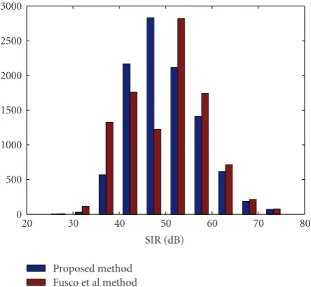
s = E[|s[n]|2] is the symbol power. The results of this set of tests are compiled and presented in the form of a histogram inFigure 9. The following observations are made from the histograms.
(i) For better channels (with smaller multipath effects), Fusco et. al. method performs better. These are cases with SIR of more than 50 dB.
(ii) On the other hand, in channels with higher level of distortion, the method proposed in this paper shows superior performance.
(iii) Since in practical channels SNR values are often below 30 dB, it is reasonable to say that both methods have satisfactory performance. Nevertheless, one may argue that the method proposed in this paper may be preferred over that of [47], as SIR values in the range of 40 dB or below are more destructive than those in the range of 50 dB or greater.
The tracking algorithms presented in Sections 7 and
8 were also tested through computer simulations. The short and long preambles were used to acquire the carrier frequency and timing phase of the received signal. Subse-quently, while the carrier and timing tracking loops were active or deactivated, the performance of the receiver in detecting the payload information symbols was studied. For the carrier tracking loop filter we followed [62] and designed a proportional and integrator loop that also counts for the delay caused by the analysis filter bank. The filter parameters that were calculated for a critically damped PLL were obtained asKp=0.1208, for the proportional gain, and KI=0.0068, for the integrator gain.
Assuming a perfect timing phase is available (or could be tracked), Figures 10 and 11 present a set of plots that show how the PLLs in CMT and SMT systems perform, respectively. The results correspond to the case where SNR is 20 dB. The upper plot in each figure shows the phase error, ϕ[n], at the loop filter input. The lower plot shows the phase jitter,φ[n], of the input signal to the analysis filter bank. As discussed in the last paragraph of Section 7, the estimated phase error in the case of CMT is more noisy than its counterpart in SMT. This is clearly seen by comparing Figures10and11.
0 500 1000 1500 2000 2500 3000
SIR (dB)
20 30 40 50 60 70 80
Proposed method Fusco et al method
Figure9: SIR comparison of (16) and (17). The histograms are based on testing over 10 000 randomly generated channels.
ϕ
[
n
]
−0.2 −0.1 0 0.1 0.2 0.3
Symbol index,n
0 100 200 300 400 500 600 700 800 900 1000
(a)
φ
[
n
]
−0.1 −0.05 0 0.05 0.1
Symbol index,n
0 100 200 300 400 500 600 700 800 900 1000
(b)
Figure10: Performance of the PLL for carrier tracking in a CMT receiver. The top figure shows the phase error,ϕ[n], at the loop filter input. The lower figure shows the phase jitter,φ[n], of the input signal to the analysis filter bank. Note that the vertical scales in two plots are different.
ϕ
[
n
]
−0.2 −0.1 0 0.1 0.2 0.3
Symbol index,n
100 200 300 400 500 600 700 800 900 1000 (a)
φ
[
n
]
−0.1 −0.05 0 0.05 0.1
Symbol index,n
100 200 300 400 500 600 700 800 900 1000 (b)
Figure11: Performance of the PLL for carrier tracking in an SMT receiver. The top figure shows the phase error,ϕ[n], at the loop filter input. The lower figure shows the phase jitter,φ[n], of the input signal to the analysis filter bank. Note that the vertical scales in two plots are different.
MSE
0 0.005 0.01 0.015 0.02 0.025 0.03 0.035
Time index,n
0 2 4 6 8 10
×103
Without tracking With tracking
Figure12: Mean square error at the output of an SMT receiver, averaged over all subcarriers, with and without a timing tracking loop.
counterpart at the receiver. As seen, without timing tracking, the MSE at the receiver output increases with time. The timing tracking loop fixes the problem and results in an MSE that remains constant, at a level slightly above the noise level. For this simulation, the SNR was set equal to 30 dB. This has an associated noise level of 0.001.
Figure 13compares the performance of CMT and SMT when both carrier and timing tracking loops are active. At
MSE
10−3 10−2 10−1 100 101
SNR (dB)
0 5 10 15 20 25 30
SMT CMT
Figure13: Comparison of the MSE of CMT and SMT in tracking mode.
SNR values of 15 dB or less both methods perform virtually the same. However, at higher values of SNR, CMT degrades. This difference is believed to be mostly due to the higher phase error/jitter at the carrier recovery loop filter output in CMT. Note that this result is in line with the theoretical results in [56] where it is found that CMT and SMT are equally sensitive to CFO and timing jitter. Here, SMT outperforms CMT, simply, because it has a less jittery PLL.
10. Conclusions
A packet format for transmission of filter bank multicarrier (FBMC) signals was proposed. The proposed packet format follows a structure similar to those of IEEE 802.11a and g, and IEEE 802.16e that are based on OFDM multicarrier signaling. It starts with a short preamble for AGC adjustment and coarse carrier acquisition. A long preamble for more accurate tuning of the carrier frequency, timing phase acqui-sition, and adjustment of the tap weights of a set of frequency domain equalizer then follows. Once these synchronization steps are performed, the receiver is ready to detect the data symbols in the payload part of the packet. To resolve any residual CFO and/or timing offset, tracking algorithms were developed. Two types of FBMC communication systems were studied. (i) Staggered multitone modulation (SMT): a system that operates based on time-staggered QAM symbols; and (ii) Cosine modulated multitone (CMT): a system that oper-ates based on PAM VSB modulated symbols. Through com-puter simulations it was found that for most parts both sys-tems perform about the same. Only the carrier tracking loop in CMT found to be more jittery than its counterpart in SMT.
Acknowledgments
References
[1] R. Van Nee and R. Prasad,OFDM for Wireless Multimedia Communications, Arthec House, Boston, Mass, USA, 2000. [2] M. Morelli, C.-C. J. Kuo, and M.-O. Pun, “Synchronization
techniques for orthogonal frequency division multiple access (OFDMA): a tutorial review,”Proceedings of the IEEE, vol. 95, no. 7, pp. 1394–1427, 2007.
[3] B. Farhang-Boroujeny and R. Kempter, “Multicarrier commu-nication techniques for spectrum sensing and commucommu-nication in cognitive radios,”IEEE Communications Magazine, vol. 46, no. 4, pp. 80–85, 2008.
[4] R. W. Chang, “High-speed multichannel data transmission with bandlimited orthogonal signals,” Bell Labs Technical Journal, vol. 45, pp. 1775–1796, 1966.
[5] B. R. Saltzberg, “Performance of an efficient parallel data transmission system,”IEEE Transactions on Communication Technology, vol. 15, no. 6, pp. 805–811, 1967.
[6] M. G. Bellanger and J. L. Daguet, “TDM-FDM transmul-tiplexer: digital polyphase and FFT,” IEEE Transactions on Communications, vol. 22, no. 9, pp. 1199–1205, 1974. [7] G. Bonnerot, M. Coudreuse, and M. G. Bellanger, “Digital
processing techniques in the 60 channel transmultiplexer,”
IEEE Transactions on Communications, vol. 26, no. 5, pp. 698– 706, 1978.
[8] B. Hirosaki, “An orthogonally multiplexed QAM system using the discrete Fourier transform,” IEEE Transactions on Communications Systems, vol. 29, no. 7, pp. 982–989, 1981. [9] H. B¨olcskei, P. Duhamel, and R. Hleiss, “Orthogonalization
of OFDM/OQAM pulse shaping filters using the discrete Zak transform,”Signal Processing, vol. 83, no. 7, pp. 1379–1391, 2003.
[10] H. B¨olcskei, “Orthogonal frequency division multiplexing based on offset QAM,” inAdvances in Gabor Analysis, H. G. Feichtinger and T. Strohmer, Eds., Birkh¨auser, Boston, Mass, USA, 2003.
[11] H. B¨olcskei, P. Duhamel, and R. Hleiss, “Design of pulse shap-ing OFDM/OQAM systems for high data-rate transmission over wireless channels,” inProceedings of IEEE International Conference on Communications (ICC ’99), vol. 1, pp. 559–564, Vancouver, Canada, 1999.
[12] H. H. Chen and X. D. Cai, “Waveform optimization for OQAM-OFDM systems by using nonlinear programming algorithms,” inProceedings of the 47th IEEE Vehicular Tech-nology Conference (VTC ’97), vol. 3, pp. 1385–1389, Phoenix, Ariz, USA, May 1997.
[13] G. Cariolaro and F. C. Vagliani, “OFDM scheme with a half complexity,” IEEE Journal on Selected Areas in Communica-tions, vol. 13, no. 9, pp. 1586–1599, 1995.
[14] L. Vangelista and N. Laurenti, “Efficient implementations and alternative architectures for OFDM-OQAM systems,” IEEE Transactions on Communications, vol. 49, no. 4, pp. 664–675, 2001.
[15] S. Pfletschinger and J. Speidel, “Optimized impulses for multicarrier Offset-QAM,” in Proceedings of IEEE Global Telecommunications Conference (GLOBECOM ’01), vol. 1, pp. 207–211, San Antonio, Tex, USA, November 2001.
[16] P. Siohan, C. Siclet, and N. Lacaille, “Analysis and design of OFDM/OQAM systems based on filterbank theory,”IEEE Transactions on Signal Processing, vol. 50, no. 5, pp. 1170–1183, 2002.
[17] P. P. Vaidyanathan, Multirate Systems and Filter Banks, Prentice-Hall, Englewood Cliffs, NJ, USA, 1993.
[18] M. A. Tzannes, M. C. Tzannes, and H. Resnikoff, “The DWMT: a multicarrier transceiver for ADSL using M-band wavelet transforms,” Tech. Rep. T1E1.4/93-067, ANSI Contribution, 1993.
[19] M. A. Tzannes, M. C. Tzannes, J. Proakis, and P. N. Heller, “DMT systems DWMT systems and digital filter banks,” in
Proceedings of the IEEE International Conference on Commu-nications (SUPERCOMM/ICC ’94), vol. 1, pp. 311–315, New Orleans, La, USA, May 1994.
[20] S. D. Sandberg and M. A. Tzannes, “Overlapped discrete multitone modulation for high speed copper wire communi-cations,”IEEE Journal on Selected Areas in Communications, vol. 13, no. 9, pp. 1571–1585, 1995.
[21] B. Farhang-Boroujeny, “Multicarrier modulation with blind detection capability using cosine modulated filter banks,”IEEE Transactions on Communications, vol. 51, no. 12, pp. 2057– 2070, 2003.
[22] N. J. Fliege,Multirate Digital Signal Processing, John Wiley & Son, New York, NY, USA, 1994.
[23] N.J. Fliege, “Modified DFT polyphase SBC filter banks with almost perfect reconstruction,” inProceedings of International Conference on Acoustics, Speech, and Signal Processing (ICASSP ’94), vol. 3, pp. 149–152, Adelaide, Australia, April 1994. [24] T. Karp and N. J. Fliege, “Modified DFT filter banks with
perfect reconstruction,” IEEE Transactions on Circuits and Systems II, vol. 46, no. 11, pp. 1404–1414, 1999.
[25] R. Bregovi´c and T. Saram¨aki, “A systematic technique for designing linear-phase FIR prototype filters for perfect-reconstruction cosine-modulated and modified DFT filter-banks,”IEEE Transactions on Signal Processing, vol. 53, no. 8, pp. 3193–3201, 2005.
[26] S. Salcedo-Sanz, F. Cruz-Roldan, C. Heneghan, and X. Yao, “Evolutionary design of digital filters with application to subband coding and data transmission,”IEEE Transactions on Signal Processing, vol. 55, no. 4, pp. 1193–1203, 2007. [27] P. N. Heller, T. Karp, and T. Q. Nguyen, “A general formulation
of modulated filter banks,” IEEE Transactions on Signal Processing, vol. 47, no. 4, pp. 986–1002, 1999.
[28] http://www.ieee802.org/11/. [29] http://www.ieee802.org/16/.
[30] T. M. Schmidl and D. C. Cox, “Robust frequency and timing synchronization for OFDM,” IEEE Transactions on Communications, vol. 45, no. 12, pp. 1613–1621, 1997. [31] M. Morelli and U. Mengali, “An improved frequency offset
estimator for OFDM applications,” IEEE Communications Letters, vol. 3, no. 3, pp. 75–77, 1999.
[32] T. M. Schmidl and D. C. Cox, “Robust frequency and timing synchronization for OFDM,” IEEE Transactions on Communications, vol. 45, no. 12, pp. 1613–1621, 1997. [33] M. Morelli and U. Mengali, “Improved frequency offset
estimator for OFDM applications,” IEEE Communications Letters, vol. 3, no. 3, pp. 75–77, 1999.
[34] H. B¨olcskei, “Blind estimation of symbol timing and carrier frequency offset in wireless OFDM systems,”IEEE Transactions on Communications, vol. 49, no. 6, pp. 988–999, 2001. [35] P. Ciblat and E. Serpedin, “A fine blind frequency offset
estimator for OFDM/OQAM systems,”IEEE Transactions on Signal Processing, vol. 52, no. 1, pp. 291–296, 2004.
[36] T. Fusco and M. Tanda, “Blind frequency-offset estimation for OFDM/OQAM systems,” IEEE Transactions on Signal Processing, vol. 55, no. 5, pp. 1828–1838, 2007.
[38] T. Fusco and M. Tanda, “ML frequency offset and carrier phase estimation in OFDM systems with noncircular transmissions,” inProceedings og the 12th European Signal Processing Confer-ence (EUSIPCO ’04), pp. 897–900, Vienna, Austria, September 2004.
[39] G. Lin, L. Lundheim, and N. Holte, “Blind carrier frequency offset estimation for OFDM/OQAM systems based on sub-channel signals,” inProceedings of Global Telecommunications Conference (GLOBECOM ’06), pp. 1–6, San Francisco, Calif, USA, November-December 2006.
[40] G. Lin, L. Lundheim, and N. Holte, “New methods for blind fine estimation of carrier frequency offset in OFDM/OQAM systems,” inProceedings of IEEE Workshop on Signal Processing Advances in Wireless Communications (SPAWC ’06), pp. 1–5, 2006.
[41] B. Jahan, M. Lanoisel`ee, G. Degoulet, and R. Rabineau, “Full synchronization method for OFDM/OQAM and OFDM/QAM modulations,” inProceedings of the 10th IEEE International Symposium on Spread Spectrum Techniques and Applications (ISSSTA ’08), pp. 344–348, August 2008. [42] B. Jahan, M. Lanoisel`ee, G. Degoulet, and R. Rabineau,
“Frame synchronization method for OFDM/QAM and ODFM/OQAM modulations,” inProceedings of the 4th IEEE International Conference on Circuits and Systems for Commu-nications (ICCSC ’08), pp. 445–449, May 2008.
[43] J. A. Lopez-Salcedo and G. Vazquez, “Cyclostationary joint phase and timing estimation for staggered modulations,” in
Proceedings of IEEE International Conference on Acoustics, Speech and Signal Processing (ICASSP ’04), vol. 4, pp. 833–836, May 2004.
[44] T. Fusco, A. Petrella, and M. Tanda, “Data-aided symbol timing estimation for multiple access OFDM/OQAM sys-tems,” in Proceedings of IEEE International Conference on Communications (ICC ’09), Dresden, Germany, June 2009. [45] T. Fusco, A. Petrella, and M. Tanda, “Joint symbol timing
and CFO estimation in multiuser OFDM/OQAM systems,” in
Proceedings of IEEE Workshop on Signal Processing Advances in Wireless Communications (SPAWC ’09), pp. 613–617, Perugia, Italy, June 2009.
[46] T. Fusco, A. Petrella, and M. Tanda, “Data-aided time-domain synchronization for filter bank multicarrier systems,” inProceedings of 16th European Signal Processing Conference (EUSIPCO ’08), August 2008.
[47] T. Fusco, A. Petrella, and M. Tanda, “A data-aided symbol timing estimation algorithm for OFDM/OQAM systems,” in
Proceedings of IEEE International Conference on Communica-tions (ICC ’09), Dresden, Germany, June 2009.
[48] L. Lin and B. Farhang-Boroujeny, “Cosine-modulated multi-tone for very-high-speed digital subscriber lines,”EURASIP Journal on Applied Signal Processing, vol. 2006, Article ID 19329, 16 pages, 2006.
[49] R. D. Gitlin and E. Ho, “The performance of staggered quadrature amplitude modulation in the presence of phase jitter,”IEEE Transactions on Communications, vol. 23, no. 3, pp. 348–352, 1975.
[50] G. Cherubini, E. Eleftheriou, and S. Olcer, “Filtered multitone modulation for VDSL,” inProceedings of Global Telecommuni-cations Conference (GLOBECOM ’99), vol. 2, pp. 1139–1144, 1999.
[51] G. Cherubini, E. Eleftheriou, S. Olcer, and J. M. Cioffi, “Filter bank modulation techniques for very high-speed digital subscriber lines,”IEEE Communications Magazine, vol. 38, no. 5, pp. 98–104, 2000.
[52] G. Cherubini, E. Eleftheriou, and S. Olcer, “Filtered multitone modulation for very high-speed digital subscriber lines,”IEEE Journal on Selected Areas in Communications, vol. 20, no. 5, pp. 1016–1028, 2002.
[53] T. Wang, J. G. Proakis, and J. R. Zeidler, “Interference analysis of filtered multitone modulation over time-varying frequency-selective fading channels,” IEEE Transactions on Communications, vol. 55, no. 4, pp. 717–727, 2007.
[54] P. Amini and B. Farhang-Boroujeny, “Per-tone equalizer design and analysis of filtered multitone communication systems over time-varying frequency-selective channels,” in
Proceedings of IEEE International Conference on Communica-tions (ICC ’09), Dresden, Germany, June 2009.
[55] A. M. Tonello, “Performance limits for filtered multitone modulation in fading channels,”IEEE Transactions on Wireless Communications, vol. 4, no. 5, pp. 2121–2135, 2005.
[56] B. Farhang-Boroujeny and C.H. (George) Yuen, “Tutorial review and comparison of cosine modulated and offset QAM filter bank multicarrier techniques,” Accepted for publication inEURASIP Advances in Signal Processing.
[57] A. Fort and W. Eberle, “Synchronization and AGC proposal for IEEE 802.11a burst OFDM systems,” inProceedings of IEEE Global Telecommunications Conference (GLOBECOM ’03), vol. 3, pp. 1335–1338, San Francisco, Calif, USA, December 2003. [58] N. Arrue, I. Velez, J. F. Sevillano, and L. Fontan, “Two coarse
frequency acquisition algorithms for OFDM based IEEE 802.11 standards,”IEEE Transactions on Consumer Electronics, vol. 53, no. 1, pp. 33–38, 2007.
[59] J. G. Proakis, Digital Communications, McGraw-Hill, New York, NY, USA, 3rd edition, 1995.
[60] B. Farhang-Boroujeny, Signal Processing Techniques for Soft-ware Radios, Lulu, 3rd edition, 2008.
[61] B. Farhang-Boroujeny, “A square-root Nyquist (M) filter design for digital communication systems,”IEEE Transactions on Signal Processing, vol. 56, no. 5, pp. 2127–2132, 2008. [62] J. Wilson, A. Nelson, and B. Farhang-Boroujeny, “Parameter