Simultaneous Binding
Proxy Mobile IPv6
Author:
K. Idserda
Graduation committee:
Telematica Instituut
Dr.ir. Mortaza S. Bargh Dr.ir. Henk Eertink
University of Twente
Dr.ir. Geert Heijenk Dr.ir. Georgios Karagiannis
Simultaneous Binding Proxy Mobile IPv6 K. Idserda
Master's Thesis
Telematica Instituut PO Box 589
7500 AN Enschede The Netherlands
Design and Analysis of Communication Systems Faculty of EEMCS
University of Twente PO Box 217
7500 AE Enschede The Netherlands
Abstract
Acknowledgements
This thesis could not have been written without the support of the following people.
First, I would like to thank Mortaza Bargh from Telematica Instituut for his inexhaustible support and many suggestions. I’m also grateful for the feedback I received from the rest of the graduation committee: Henk Eertink from Telematica Instituut and Geert Heijenk and Georgios Karagiannis from the University of Twente.
I would also like to thank Julien Laganier, Alf Zugenmaier and Anand Prasad for their help with the testbed at DOCOMO Euro-Labs in Munich.
Finally, I thank my parents for supporting me throughout my studies. Enschede, December 5th, 2008.
Contents
Abstract... III
List of Figures... IX
List of Tables ... XI
Abbreviation list ...XII
1.
Introduction ... 15
1.1. Research context... 15
1.2. Problem statement and objectives ... 16
1.3. Approach ... 18
1.4. Outline ... 19
2.
Background... 20
2.1. IPv6 mobility-related features ... 20
2.1.1. Address types...20
2.1.2. Neighbor discovery...21
2.1.3. Address configuration...22
2.1.4. Duplicate address detection ...22
2.1.5. Detecting network attachment ...25
2.2. IP level mobility protocols ... 25
2.2.1. Host based ...25
2.2.2. Network based ...29
2.3. Related work... 30
3.
Protocol description... 32
3.1. Introduction ... 32
3.1.1. Overview ...32
3.1.2. Objectives ...32
3.1.3. Design...33
3.1.4. Protocol operation...34
3.1.5. Typical message exchange ...35
3.2. Preconditions ... 36
3.2.1. Triggers...36
3.2.3. Mobile node capabilities...38
3.3. Node operation ... 39
3.3.1. Local mobility anchor...39
3.3.2. Mobile access gateway ...40
3.3.3. Mobile node...43
3.4. Message formats ... 44
3.4.1. Proxy binding update request ...44
3.4.2. Proxy binding update acknowledgement...45
3.4.3. Simultaneous proxy binding update request...45
3.4.4. Simultaneous proxy binding update acknowledgement ...46
3.4.5. Options ...46
4.
Performance evaluation ... 49
4.1. Testbed... 49
4.1.1. Hardware ...49
4.1.2. Software...51
4.1.3. SPMIPv6 implementation...53
4.2. SPMIPv6 results ... 54
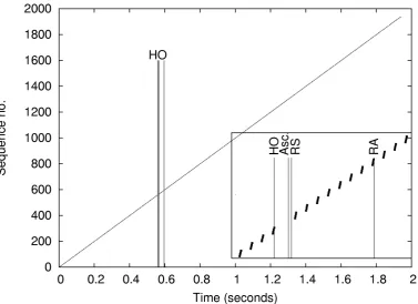
4.2.1. UDP ...55
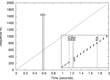
4.2.2. TCP...57
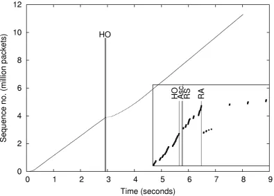
4.3. Buffer size impact... 64
4.4. SPMIPv6 and PMIPv6 performance comparison... 65
4.5. Analysis ... 67
4.5.1. Timing of prediction...68
4.5.2. Bandwidth usage in the network...72
5.
Conclusion and future directions... 77
5.1. Conclusion... 77
5.2. Future work... 78
Appendix A: UMTS Connection setup ... 79
List of Figures
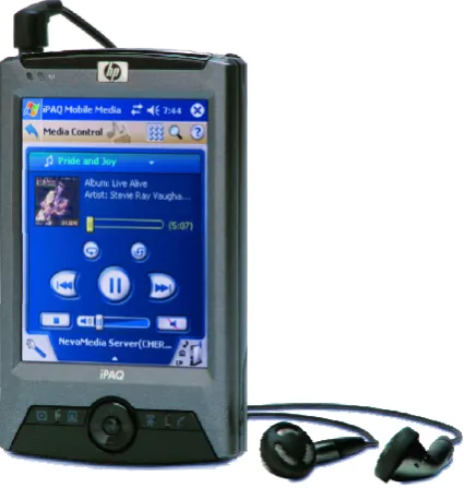
Figure 1: PDA playing streaming music ... 15
Figure 2: TCP/IP Model... 16
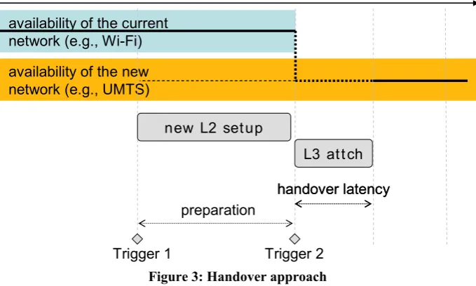
Figure 3: Handover approach... 19
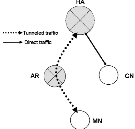
Figure 4: MIPv6: MN communicates with CN via HA ... 26
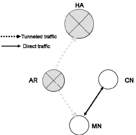
Figure 5: MIPv6: MN communicates directly with MIPv6 capable CN... 27
Figure 6: PMIPv6 network layout and communication ... 29
Figure 7: PMIPv6 boot up sequence ... 30
Figure 8: SPMIPv6 typical network layout... 34
Figure 9: SPMIPv6 Handover message exchange ... 36
Figure 10: FSM of LMA operation ... 40
Figure 11: FSM of oMAG operation... 41
Figure 12: FSM of nMAG operation... 42
Figure 13: FSM of MN operation ... 43
Figure 14: PBUR message format... 44
Figure 15: PBUA message format ... 45
Figure 16: SPBUR message format ... 45
Figure 17: SPBUA message format ... 46
Figure 18: NAI option format ... 47
Figure 19: Home network prefix option format ... 47
Figure 20: Timestamp option format ... 48
Figure 21: Picture of the testbed ... 50
Figure 22: Testbed setup ... 51
Figure 23: SPMIPv6 UDP downstream traffic without buffering... 56
Figure 24: SPMIPv6 UDP downstream traffic with 7 ms buffering ... 57
Figure 25: SPMIPv6 TCP downstream traffic without buffering ... 58
Figure 26: SPMIPv6 TCP downstream traffic without buffering, with ACKs ... 59
Figure 27: SPMIPv6 TCP downstream traffic with 7 ms buffering... 60
Figure 28: SPMIPv6 TCP downstream traffic with 100 ms buffering... 61
Figure 29: SPMIPv6 TCP downstream traffic with 100 ms buffering, with ACKs... 62
Figure 30: SPMIPv6 TCP upstream traffic without buffering ... 63
Figure 31: SPMIPv6 TCP upstream traffic with 100 ms buffering... 64
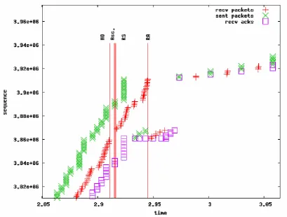
Figure 32: SPMIPv6 traffic flow after a handover... 66
Figure 33: PMIPv6 UDP downstream traffic... 66
Figure 34: PMIPv6 TCP downstream traffic ... 67
Figure 35: Message exchange after trigger 1 ... 70
Figure 36: Handover latency Dnetwork > Dlayer2... 70
Figure 37: Handover Latency Dnetwork
≅
Dlayer2... 72Figure 38: Handover Latency Dnetwork < Dlayer2... 72
Figure 39: Bicast start and stop timing... 75
Figure 40: Bicast active versus extra load in network... 76
Figure 41: Delay classes... 81
List of Tables
Table 1: IPv6 address types... 21
Table 2: Message exchange in the testbed to activating bicasting ... 54
Table 3: Buffer sizes impact... 65
Table 4: Variables used in analysis of handover latency ... 68
Table 5: Definition of variables used in analysis of handover latency... 69
Table 6: Maximum handover latency when Dnetwork >> Dlayer2... 70
Table 7: Dho with layer 2 delays ... 71
Table 8: Variables used in bandwidth usage model ... 74
Table 9: Delay classes... 80
Table 10: Numerical values for delays... 84
Table 11: Connection process parts ... 85
Abbreviation list
3GPP 3rd Generation Partnership Project
AR Access Router
BBM Break Before Make
BU Binding Update
CoA Care of address
DAD Duplicate Address Detection
DNAv6 Detecting Network Attachment version 6 DSL Digital Subscriber Line
FBA Fast Binding Acknowledgment
FBU Fast Binding Update
FMIPv6 Fast Mobile Internet Protocol v6 FNA Fast Neighbor Advertisement GPRS General Packet Radio Service
GSM Global System for Mobile communications
HA Home Agent
HAck Handover Acknowledgment
HI Handover Initiate
HMIPv6 Hierarchical Mobile Internet Protocol version 6
HoA Home Address
ICMP Internet Control Message Protocol
IEEE Institute of Electrical and Electronics Engineers
IP Internet Protocol
IPv4 Internet Protocol version 4 IPv6 Internet Protocol version 6 LCoA Local Care of Address LLA Link Local Address LMA Local Mobility Anchor LTE Long Term Evolution MAC Media Access Control MAG Mobility Access Gateway MAP Mobility Anchor Point
MBB Make Before Brake
MIPv6 Mobile IPv6
MN Mobile Node
MnAP Mobile-node Attachment Point MNID Mobile Node Identifier
NA Neighbor Advertisement NAI Network Access Identifier
NAR New Access Router
ND Neighbor Discovery
nMAG new MAG
NS Neighbor Solicitation
oMAG old MAG
PAR Previous Access Router
PBUA Proxy Binding Update Acknowledgment PBUR Proxy Binding Update Request
PDA Personal Digital Assistant PDP Packet Data Protocol
PMIPv6 Proxy Mobile Internet Protocol version 6 PrRtAdv Proxy Router Advertisement
QoS Quality of Service RA Router Advertisement RCoA Regional Care of Address RFC Request for Comments RIP Regional Information Point RS Router Solicitation
RtSolPr Router Solicitation for Proxy Advertisement SAE System Architecture Evolution
SPBUA Simultaneous Binding Update Acknowledgment SPBUR Simultaneous Binding Update Request
SPMIPv6 Simultaneous binding Proxy Mobile Internet Protocol version 6 SSID Service Set Identifier
1. Introduction
1.1.
Research context
A wide range of wireless communication systems is available nowadays. Wireless network technologies like Global System for Mobile communications (GSM) and Universal Mobile Telecommunications System (UMTS) [1] offer a large coverage area, but have limited bandwidth and can be expensive to use. On the other side we have Wi-Fi technology (based on IEEE802.11 standard [2]), which offers a large bandwidth in a small coverage area, for a relatively cheap price. There is also the emerging Mobile WiMax technology [3] (based on the IEEE802.16e [4] standard), sitting in between when looking at both bandwidth and coverage area.
New communication devices like Personal Digital Assistants (PDAs) and smart-phones are able to connect to more than one of such wireless technologies. When these connections all offer the same capabilities (e.g., Internet Protocol (IP) data transport), the most appropriate (and available) wireless technology can be used. It would be possible to use Wi-Fi if the user is within range of a hotspot and needs a lot of bandwidth at that time. But, as said, Wi-Fi does not have a large coverage area. When moving out of range, the ongoing communication sessions should be transferred to, for example, UMTS. This connection transfer is called a handover, which typically disrupts the connection for some period called “handover latency”.
Figure 1: PDA playing streaming music
video, both of which may stutter or even stop during a handover from one access technology to another.
To be able to support applications like these future networks must be able to support handover with the smallest amount of handover latency possible.
1.2.
Problem statement and objectives
Today’s communication networks are evolving towards an all-IP architecture [5]. This means that these communications networks will merge towards a heterogeneous network where different access technologies are all using IP as a common denominator. Development of such evolved communication networks is done by the 3rd Generation Partnership Project (3GPP), an organization that standardized GSM and UMTS in the past. They are working on a new mobile access technology standard called Long Term Evolution [6] (LTE). This new standard aims for increased data rates and a higher Quality of Service (QoS). The architecture of the IP-based core network for this will evolve towards the System Architecture Evolution [7] (SAE), which will provide support for more flexible handover towards other (fixed) networks, including IEEE802-type networks. A clear specification that will meet all requirements for a seamless handover is however still in development.
In an all-IP network, a lot of different TCP/IP layer-2 (data link layer, see Figure 2) [8] protocols such as Wi-Fi, UMTS or a wired technology such as any form of DSL (Digital Subscriber Line) will all be operating under this all-IP network. The IP layer sits on top of all these access technologies, which means that the protocol that supports mobility in the network is also assumed to be IP based. Internet Protocol version 6 (IPv6) [9] is the next generation of the currently used IPv4 [10] protocol, which is expected to be used widely in the near future. IPv6 includes a protocol to handle mobility issues, called Mobile IPv6 (MIPv6) [11]. This protocol hides movement of a node in the network, which means changing its point of attachment, for the applications running on the Mobile Node (MN). It operates on top of any other layer 2 technology. However, the different characteristics of these layer 2 technologies make a seamless handover difficult for Mobile IPv6.
We can distinguish two categories of handover: vertical handover and horizontal handover. The term vertical handover is used when a handover occurs from one technology type (for example Wi-Fi) to another (i.e. UMTS). When a handover occurs within a network technology type, e.g., from one Wi-Fi access point to another, we use the term ‘horizontal handover’.
Handovers can be on layer 2, requiring the MN to connect to a new access point without changing the subnet, or also on layer 3, when connecting to a link that is on a different IP-subnet. Furthermore, a handover can be within the same administrative domain (intra-domain handover) or between two different administrative domains (inter-domain handover).
Considering the types of wireless technologies involved in a handover, timing of the actual handover is crucial for a seamless continuation of ongoing data transfers on the new connection. On layer 2, it might be possible to connect to a new access network while still maintaining a connection to the old one. This is called Make Before Break (MBB). The opposite happens when for example a device is not capable of using two network interfaces at the same time or when the device is capable of using two network interfaces at the same time, but has not anticipated a sudden handover. This is called Break Before Make (BBM). This means that the old connection is lost before a new connection to the second network is fully activated. Note that we are talking about layer 2 here. On layer 3, both MBB and BBM are possible. In the case of MBB, the MN will get a second IP address that is active on the new connection. In layer 3 BBM, the MN will configure its IP address when the old connection is lost.
As a preliminary to this research we looked at the connection setup process in UMTS. This roughly consists of three parts: establishing a radio connection between the MN and the network, the General Packet Radio Service (GPRS) attach process (authentication and registering in the MN in the network) and finally the PDP (Packet Data Protocol) context activation, which gives the MN a valid IP address. This whole process takes about 1250 ms. When we look at a BBM handover (both on layer 2 and layer 3) towards UMTS this would mean that the handover latency would be this same amount, which is much too large to continue for example a VoIP call without any disruptions. We tried to see if certain parts of the UMTS connection process could be carried out in advance, resulting in a smaller handover latency. The minimum delay we could achieve, which was by only having to set up a radio channel between MN and the network, was around 180 ms, which is still too large. From this we concluded that a MBB handover towards UTMS with the total connection in place is the only way to achieve a seamless handover.
The goal of this thesis is to design and validate a mobility protocol that:
- is IP based, so it can be used on the future all-IP SAE/LTE network. For this, mobility protocols available in IPv6 can be used as a starting point.
- supports both vertical and horizontal handovers towards different layer 2 technologies. - provides seamless handovers with a maximum handover latency of 50 ms, to support
applications such as VoIP.
- is proactive, to support large layer 2 setup delays.
- also does preparations for a handover in the network itself to minimizes packet loss How this will be accomplished is explained in the next section.
1.3.
Approach
Considering all the factors mentioned above, we aim at finding solutions that minimize the handover latency period caused by a handover from one access point to another. We consider a scenario where the MN experiences a handover from one access network to another. The handover can be vertical (from Wi-Fi towards UMTS) or horizontal (from one Wi-Fi access point to another where the access points have a different SSID). We require the coverage areas of the current and the new network to overlap during the handover period. Further, we require that the MN is not capable of having layer 3 connectivity to both networks at the same time during the handover. The MN, however, is capable of having layer 2 connections to two different access networks simultaneously for the handover duration. We mainly focus on Wi-Fi (802.11) and UMTS as layer 2 wireless network technologies.
availability of the current network (e.g., Wi-Fi)
availability of the new network (e.g., UMTS) availability of the current network (e.g., Wi-Fi)
availability of the new network (e.g., UMTS)
new L2 setup
L3 att ch
Trigger 1 Trigger 2
preparation
handover latency handover latency
Figure 3: Handover approach
The objective is to attain the maximum handover latency of 50 ms, as required in [12],[13]. In this, it states that in order to support real-time streams such as VoIP in a handover between different radio technologies the packet transmission delay fluctuations should be less then this 50 ms. In order to determine if the protocol lives up to this, we will implement SPMIPv6 in a testbed and carry out tests to measure the handover latency and to determine the impact of the handover latency on both UDP and TCP protocols when transporting upstream and downstream data flows.
1.4.
Outline
2. Background
This chapter describes all relevant mobility aspects and protocols used in the rest of this report. The main focus is on the mobility features of IPv6 that are present in the network. Those features that are embedded in IPv6 for mobility detection and configuration are described in section 2.1. Specific IP-level signaling protocols that deal with IP-level mobility are explained in section 2.2. In section 2.3, related work with respect to our solution, the SPMIPv6 protocol, is presented.
2.1.
IPv6 mobility-related features
IPv6 [9] is the successor of the widely used IPv4. It has many improvements over the old IPv4. We will use IPv6 as the base of the mobility protocol instead of IPv6 since it has more advanced mobility aspects than IPv4 and will probably be widely used in the near future. IPv6’s features include expanded addressing capabilities, as the size of the IP address is increased from 32 to 128 bits. The scalability of multicasting is improved and an anycast address type is introduced, which can be used to send packets to any one of a group of nodes. Address types are explained in section 2.1.1. It is also possible for a node to obtain a valid IPv6 address using stateless auto configuration. Stateful configuration using for example a DHCP server is also still supported. Address configuration is explained in section 2.1.3. In the remaining of this section the various aspects of IPv6 which are of importance for mobility support will be explained.
2.1.1. Address types
An IPv6 node has multiple types of addresses [14],[15]. A node typically has a loop-back address, a Link-Local Address (LLA) per network interface and one or more global unicast addresses. A node may also have multiple multicast addresses, i.e., the MN may be a member of several multicast groups.
The standard way to represent an IPv6 address is by showing it as eight 16-bit hexadecimal words, separated by colons. For example: FEDC:BA98:0000:0000:0000:000C:2154:7313. Since a large number of IPv6 addresses contain multiple fields of only zeros, the notation can be compressed. These fields with only zeroes can be replaced by a double colon (::). Also, leading zeros may be omitted. The address in the previous example can thus be written as FEDC:BA98::C:2154:7313. An IPv6 (sub)net can be denoted by the starting address of the subnet and the size in bits of the address prefix. So, FEDC:BA98::/32 is the subnet in which the previous example lies.
Address type Range
Link-local FE80::/8
Global unicast 2000::/3
Multicast FF00::/8
Loopback ::1/128
Table 1: IPv6 address types
The link-local address is only used for communication with nodes that are on the same link, for example the Access Router (AR). This address is formed by appending the interface’s identifier to the link-local prefix, which is well-known (FE80::0). This identifier can be
determined in several ways. The first is to use the EUI-64 (Extended Unified Identifier) identifier, as defined by the IEEE (Institute of Electrical and Electronics Engineers) [16]. If this is not available, it is also possible to use a link layer identifier, such as the MAC (Media Access Control) address in Ethernet. The 48-bit MAC address is then converted into a modified EUI-64 identifier by flipping the 7th bit and inserting ‘fffe’ between the 3rd and 4th
byte of the MAC address.
The global unicast address is an address type that is routable throughout the whole Internet. There are several special multicast addresses. FF02::1 is used to address nodes on the link
(link multicast address). The prefix FF02::1:FF00:0/104 followed by 24 bits of the
MN’s unicast address is the solicited node address. This address is used by the Neighbor Discovery (ND) protocol.
The loopback interface is only used on the host itself. It is the equivalent to 127.0.0.1 (or ‘localhost') in IPv4. The unspecified address type has all bits set to zero.
2.1.2. Neighbor discovery
The neighbor discovery protocol [17] is used
1. to determine the link-layer addresses for neighbors on the same link (address resolution).
2. to find neighbor routers that can forward packets.
3. to determine which neighbors are still reachable and which are not. Changed link layer addresses are also detected this way.
Sometimes sending traffic to a certain host through the default AR is not the most efficient way. To solve this, routers can send redirect messages to inform hosts that a better first-hop router is available for a specific destination. Or, in case the destination host is on the same link, to let the host know that the destination is in fact a neighbor, reachable on the local link. It is possible for any IPv6 node to broadcast an unsolicited Neighbor Advertisement (NA) message, when for example its layer 2 address has changed. This causes all other nodes on the same link to update their address resolution cache.
2.1.3. Address configuration
With IPv6, it is possible to automatically configure an interface [18]. This process consists of creating a link-local address, verifying its uniqueness and determining what settings, e.g., global IP addresses and default AR, should be auto configured. Global addresses can be configured using a stateless or stateful mechanism. The stateless procedure can be used when the network is not concerned with exact addresses handed out to a host, as long as the address is unique and properly routable. When tighter control is required the stateful method can be used. Both methods can be used simultaneously. An address can be acquired using the stateless mechanism, while the stateful method provides hosts with other information about for example domain name servers.
Routers periodically send out Router Advertisement (RA) messages. These messages contain various link and Internet parameters, such as prefixes that can be used for address configuration. This prefix is used by hosts to configure a global address. If a host whishes to receive this information direct, rather than having to wait for a periodical message, it can send a Router Solicitation (RS) message to the all-routers multicast address. A router will reply to this by directly sending a RA to the originator of the RS message. The link-local address of the sender is used a destination for this RA. Both RA and RS are a specific type of Internet Control Message Protocol (ICMP) message.
Before any address can be used, the host has to verify that there is no other node using this address. This is called Duplicate Address Detection (DAD), which is explained further in the next section. The assigned IPv6 address has a fixed (possibly infinite) lifetime. When just obtained and its uniqueness verified, an address is in the ‘preferred’ state. Its use is then unrestricted. An address can become ‘deprecated’ later, meaning that using the address is discouraged. Ongoing connections can still use it, but new connections should use a ‘preferred’ address.
All this has to be done before a node can start sending or receiving any data. In section 2.5.1, DNAv6 is described, which speeds up the whole address configuration process.
2.1.4. Duplicate address detection
When using stateless autoconfiguration, the uniqueness of an address is determined by the uniqueness of the interface identifier, which is appended to the subnet prefix to form a complete address. If we assume that these prefixes are assigned correctly and that a host uses the same identifier for all its addresses, we only have to perform DAD on one address. So, if the link-local address is found to be unique, we can skip DAD on all other addresses.
The basic operation of the DAD protocol is that the IPv6 node sends a NS message to the link-local address it wishes to use. If it is in use, the host using it will return a NA message. Other host attempting to use this address will also send out a NS message. If no reply is received within a given amount of time, a timer expires and the address is assumed to be unique. Because a node has to wait for this timer to expire, a large delay is introduced here before the node can actually start sending packets using this address.
In case of a handover, the host will have to perform DAD on the new link before it can resume its ongoing data transfer. So, the handover latency may be increased by having to perform DAD, which is not desirable. The rest of this subsection explains several improvements to the original DAD algorithm which were considered as alternatives to be used with SPMIPv6 to speed up the layer 3 association process. All these changes to the original DAD process have the same goal: minimize the DAD period.
Optimistic DAD
With normal DAD, an address is in the ‘tentative’ state when the uniqueness of this address is being verified. In this state it is not assigned to an interface in the usual sense. No IP packets can be sent using this address and packets with the tentative address as destination are simply discarded by the interface on the host that receives them. Optimistic DAD, which is described in RFC4429 [19], introduces a new address state called ‘optimistic’. This state is assigned to addresses whose uniqueness is being verified. An address in this state should be treated the same as an address that is in the deprecated state. This means that its use is discouraged, but not forbidden. The address should not be used for new communications, but existing connections can be resumed immediately after the interface is activated. Packets sent to or from this address are delivered normally. When DAD is performed successfully on this address, its state changes to ‘preferred’.
To use optimistic DAD, several alternations have to be made to the ND process. Since the address in the optimistic state is in fact used before its uniqueness is checked, it is possible that the address is already in use. Several changes have to be made to the address resolution process to make sure that when the address is already in use impact to the rest of the network is minimal.
- In NA messages, the ‘Override’ flag is not set. If the address is already in use, this will not corrupt the neighbor cache of other nodes, since existing records will not be overwritten. Ongoing communication with the node that is already using the address is not disrupted.
- RS messages, multicast messages used to request address configuration information, cannot contain the link-layer address of the sending node. This means that RA replies from the AR have to be a sent to a multicast address.
When Optimistic DAD is used after a handover, the whole DAD delay period is reduced to zero, since data transfer can be resumed immediately. When DAD is complete, the address moves to the preferred state, also allowing new connections to make use of the address.
Advanced DAD
Another addition is Advanced DAD [20]. This is a proposal that cannot be found in any standard yet. Here, ARs maintain pool of unused addresses. Addresses from this pool are silently removed when a NS for this address is received.
The operation works as follows:
- Mobile nodes waiting for a prefix send RS messages with as an option a duplication-free CoA (Care of Address) request. This term (CoA) is used in different mobile IP variants to denote an (temporary) IP address that can be used by the MN on a foreign (non-home) link, see section 2.2.1 for more information on this. Including this option in the RS means that the MN wishes to receive an address that it can use directly, without having to perform DAD.
- The RS includes MN’s previous CoA and LLA. - Upon receiving this, the access router
o Select a free address from the pool
o Creates an entry in its neighbor cache with selected address and LLA
o Also sets a route to MN’s previous CoA/LLA
o Sends a unicast RA (to old CoA) which contains the new duplicate-free CoA as an option
The DAD delay period is eliminated when Advanced DAD is used. There is no need to perform DAD, since the address is guaranteed to be unique.
Proactive DAD
Another proposal is Proactive DAD [21]. This DAD procedure assumes that there is a Regional Information Point (RIP) server on each network. This RIP maintains Mobile-node Attachment Point (MnAP) tables that store information about which access routers are connected to which access points in the serving domain. It also knows the prefix that is advertised by each AR. Each RIP periodically exchanges its MnAP table with neighbor RIPs. When connecting to the network, a MN will receive all information currently stored in the RIP. It then knows all prefixes used on all access points within its area. It can use this information to determine if the access router it will move to is advertising the same prefix as it is using now.
to the new access point. But, with Proactive DAD, the MN can send a CoA_preAllocate Request message to the new AR, while still attached to the old AR. The AR will determine now if the address is unique. It sends a reply to the MN letting it know if the address is unique. If it is, the MN can now send a CoA_activation Request message to the new AR, which indicates that it is going to use the address. Now the MN can move to the new access point and can start using the new address immediately.
2.1.5. Detecting network attachment
The Detecting Network Attachment [22] addition to IPv6 (DNAv6) helps MNs to regain layer 3 connectivity quickly after connecting to a new access point. This protocol is currently being developed and is described in an Internet Draft. The protocol assumes that a change in layer 2 connectivity invokes a trigger, which is processed at layer 3. Aside from that, several other improvements are also part of DNAv6. Optimistic DAD (see section 2.1.4) is used to get a unique address and minimize the delay of duplication address detection.
After the layer 2 trigger that indicates a link change, layer 3 has to determine if it is still connected to the same link. This happens for example when multiple access points belong to the same network domain. To easily facilitate this, DNAv6 enabled routers know all the prefixes that are advertised on the link. They have learned these by listening to RA’s from other routers. The base action is now to respond to a RS by including all these prefixes in the RA. If one of these prefixes match the prefix the host was previously using, it knows the link has not changed. The MN does not have to do any duplicate address detection, since it is on the same link. These RA’s can get large when the number of prefixes is large. Because of this the MN can also include a Landmark option in the RS, which is the prefix it is currently using. If the router knows this prefix, it replies with a simple RA only containing this prefix. If it is not known, the full RA is sent.
The last improvement concerns fast router advertisements. Normally, a router should delay the sending of a RA for a random amount of time to avoid all routers on the link replying to a RS at the same time. DNAv6 solves this be letting the routers generate a ranking. The first router in this ranking sends a router advertisement with 0 seconds delay.
2.2.
IP level mobility protocols
This section describes the IPv6 mobility protocols that currently exist. First, host based protocols are described. With these, the MN takes care of his own mobility management. In the second part, network based protocols are described, in which the network is the coordinator of the handover.
2.2.1. Host based
Mobile IPv6
The address that the MN gets when it boots up in its home domain is called the ‘Home Address’ (HoA). It is always reachable through this address. When the MN moves away from the home domain, a Care-of-Address (CoA) is assigned to it. This address is acquired in the normal IPv6 way using stateless or stateful auto configuration. The MN then registers itself with a router on its home link (called the home agent (HA)) by sending a Binding Update (BU) to this HA. If the registration is valid, the HA replies with a Binding ACK. The HA now uses proxy Neighbor Discovery to represent the MN in the home network. A bidirectional tunnel is set up between the home agent and the MN. Packets coming from the MN are sent to the HA and then routed on the internet in the normal way [23]. This is shown in Figure 4. Correspondent nodes (CN) sending data to the MN will also see these packets going through the HA.
It is also possible to communicate directly with a CN, if this node also supports MIPv6. This is shown in Figure 5. To start doing this, the MN sends a BU to the CN. Packets that the MN now sends to the CN have the CoA as the source address. The CN receives these packets and replaces the source address with the HoA of the MN. Packets that the CN wants to send to the MN directly have the CoA as destination and the HoA (in a special routing header) as the second hop. In the MN the routing header is removed so that the upper layers only see the HoA.
Figure 5: MIPv6: MN communicates directly with MIPv6 capable CN
Hierarchical mobile IPv6
Hierarchical Mobile IPv6 (HMIPv6) [24] was designed to reduce the amount of signaling needed between MN, CN and HA. It does this by separating global and local mobility. A Mobility Anchor Point (MAP) is introduced into the network. This MAP can exist at any level in a hierarchical network of routers. A MAP can span multiple subnets. A MN sends BU messages to the MAP, instead of to the home agent. The MN does not need to contact all CN’s; all traffic is redirected after the one BU message is received by the MAP.
The MN has two care-of addresses in the HMIPv6 domain: the Local CoA (LCoA) and the Regional CoA (RCoA). The RCoA is used for communication with CN’s and stays the same while connected to the same MAP. The LCoA (or on-link CoA) is used to communicate with the MAP. Whenever the MN moves to a different link in the domain of the MAP it obtains a new LCoA and has to register this address with the MAP. After a successful registration to the MAP by a MN, a bi-directional tunnel is set up. Packets sent by the MN have the LCoA as source in the outer (tunnel) header and the RCoA as source of the inner header. The MAP receives these packets from the MN, removes the outer header and forwards the packet towards the CN with the RCoA as the source address.
When the MN moves out of the domain of the MAP, it tries to find a new MAP on the new access link. If there is no MAP, normal Mobile IP is used. If there is a MAP, it registers itself and gets a new RCoA from the MAP. Its LCoA will also be updated.
Fast mobile IPv6
the home agent and correspondent nodes. Packets only start arriving at the new CoA after a successful registration with home agent.
FMIP can work with both MN and network-initiated handovers. In the first mode, the MN can make use of layer 2 scanning techniques to identify other access point within its reach. While still connected to its current access router, it can already get information like other access routers L2 and IP address. This is done by sending a Router Solicitation for Proxy Advertisement (RtSolPr) message to its current access router, asking information about a certain access point identified by AP-ID. The reply to this is a Proxy Router Advertisement (PrRtAdv) message. With these messages it is also possible to already form a prospective new CoA (NCoA) that can be used when the MN moves to the new AR. This way, the latency due to the prefix discovery when connecting to a new AR can be eliminated.
When a handover occurs, the MN sends a Fast Binding Update (FBU) message; preferably to the AR it was previously connected to (the previous AR (PAR)). This is called ‘predictive mode’. When the PAR receives this message, a Handover Initiate (HI) message is sent to the new AR (NAR). This is confirmed by a Handover Acknowledge (HAck) message sent by the NAR to the PAR. A tunnel is setup between NAR and PAR. Packets that arrive at the PAR after the MN disconnects there will now be sent using the tunnel towards the NAR. The NAR will deliver them to the MN when the MN will attach there. A Fast Binding Acknowledge (FBA) is sent by the PAR to the MN and the NAR to indicate a successful handover preparation. The MN can now connect to the NAR with minimal address configuration delay and packet loss.
The second mode is called ‘reactive Fast Handover’. Here, the FBU cannot be sent on the old link. Instead, a FBU enclosed in a Fast Neighbor Advertisement (FNA) is sent to the NAR. The NAR now sends a FBU to the PAR, requesting the data for the MN to be forwarded. The PAR starts forwarding packets for the MN to the NAR and also sends an FBA.
Handover initiation can also come from the network itself. It is possible for AR to send an unsolicited PrRtAdv to the MN, when for example it knows a handover is imminent, or to inform the MN about adjacent networks.
Simultaneous bindings
Simultaneous Bindings [26] is an addition to FMIPv6. It tries to further minimize the packet loss the MN experiences. It does this by bicasting traffic for the MN to both its current location and the location it is supposed to move to in the near future. This feature was built into Mobile IPv4 [27] but is not present in Mobile IPv6. Simultaneous Bindings in FMIPv6 removes the timing ambiguity experienced with FMIPv6 regarding when to start forwarding traffic to the MN’s new location. If this timing is off, data could be sent to the new location too late or too early, both resulting in extra packet loss.
2.2.2. Network based
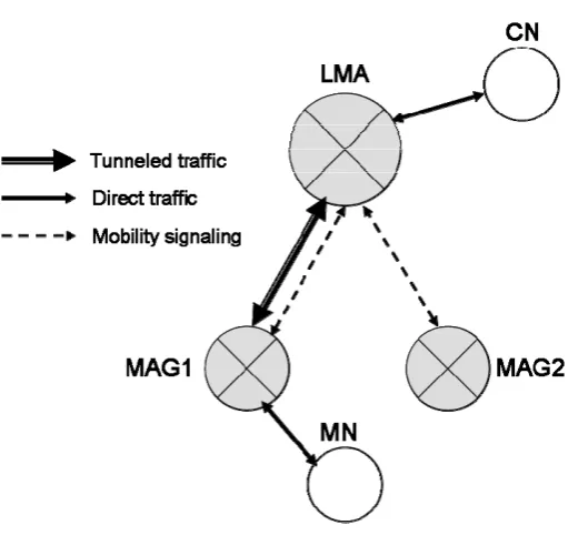
Proxy mobile IPv6
Proxy Mobile IPv6 [28] tries to offer mobility to IPv6 hosts that do not have Mobile IPv6 in their stack. This is done by extending Mobile IPv6 signaling and also by reusing the home agent via a proxy mobility agent. With this approach it is not necessary for the MN to be part of layer 3 mobility signaling. The proxy mobility agent takes care of the MN’s mobility management. This protocol can be used in networks that have both Mobile IPv6 enabled and non-Mobile IPv6 enabled nodes.
The following new nodes are introduced: - Local Mobility Anchor (LMA)
This entity is the home agent for the MN. The MN’s prefix (HoA) is in the same network as the LMA.
- Mobility Access Gateway (MAG)
The MAG takes care of the MN’s mobility signaling. It tracks the MN on the access link. All traffic for MN’s goes over a tunnel between MAG and LMA.
How these nodes connect is shown in Figure 6.
Figure 6: PMIPv6 network layout and communication
are sent to make sure the MN is still connected and that the binding is still valid. All messages that are exchanged during this process are also shown in Figure 7.
Figure 7: PMIPv6 boot up sequence
2.3.
Related work
Mobile IPv6 offers mobility to IPv6 capable nodes. While this offers the capability of retaining connectivity while moving from one network to another, ongoing connections are still impacted by the actual handover between these two networks. Nodes involved in a handover experience a certain amount of handover latency: the period when there is no connectivity to neither of the two networks. During this period of time, packets destined for the MN are lost. This amount of packet loss is a direct consequence of the handover latency period. This handover latency is composed of several parts:
- Layer 2 setup delay. Before any packets can be received on the new connection, the lower level layers (such as 802.11 or UMTS) have to be connected. A study of the connection setup process of UMTS (see Appendix A) has shown that this delay is a big factor in the overall handover latency.
- Layer 3 setup delay. This delay consists of the delay caused by layer 3 address configuration.
complete that the MN can receive packets at its new location. This binding update message must also be sent to CN with which direct communication was established previously.
To make the handover process more seamless, the handover latency period has to be minimized. Several attempts have been done to do this. HMIPv6 tries to reduce the registration delay by introducing local and global mobility. If the MN moves within the local domain, registration messages do not have to be sent to the home agent, reducing this delay factor to 0. However if the MN moves out of the local domain, binding updates still have to be sent to the home agent. FMIPv6 reduces the layer 3 (address configuration) delay by determining the appropriate address settings on the new connection before the actual handover. It also has the possibility to let the old access router forward packets to the new access router. This forwarding does not reduce the handover latency, but fewer packets are lost this way. This forwarding is activated when the MN disconnects at its current access point (layer-2 handoff). It can be difficult in some situation to determine this exact moment. FMIPv6 and HMIPv6 can be combined, reducing both layer 3 setup and registration delay. By introducing simultaneous bindings, traffic can be forwarded to both the current and new access router. By using this the exact time of the layer-2 handoff does not have to be known for this mechanism to reduce packet loss.
Simulations have been done with several of these protocols. It was shown that a combination of HMIPv6 and FMIPv6 scores the best when overall handover latency is concerned [29]. This makes it the most suitable for real time traffic. Mobile IPv6 with simultaneous binding scores the best when a low packet loss is desired. Analytical results show that when the delay in the network is smaller than the delay on the wireless link, HMIPv6 performs better. This is because FMIPv6 uses more signaling between MN and AR, which traverse the slower wireless link [30]. If the delay in the network is larger than the delay on the air interface, a combination of HMIPv6 and FMIPv6 shows the smallest handover latency.
There is a proposal [31] that adds bicasting and buffering to FMIPv6 handovers. When a MN sends a fast binding update to its PAR, the PAR will start bicasting packets for this MN to the NAR. Packets are also delivered to the MN. The NAR buffers these packets for the MN until it moves over to this AR. Using this, no packets are lost when the MN moves to the NAR prematurely. A special header [32] is appended to bicasted packets. The MN can use this header to check for duplicate packets after it moves to the NAR and receives buffered packets there.
3. Protocol description
3.1.
Introduction
This chapter will describe the SPMIPv6 protocol. It starts with a description of the protocol requirements and how they are met. Prerequisites and assumptions for the protocol to function are then explained. Messages formats and node operation conclude the specification.
3.1.1. Overview
Simultaneous binding Proxy Mobile IPv6 (SPMIPv6) is a network based mobility protocol. It is based on Proxy Mobile IPv6 (PMIPv6), which in turn is based on the Mobile IPv6 (MIPv6) specification. It enables hosts using IPv6 to change their point of attachment in the network with a minimized amount of service disruption. It does this by preparing for a handover before the actual disconnect at the hosts occurs. Both the network and the MN are part of the handover preparation process.
3.1.2. Objectives
The main objective of the protocol is to support seamless handover from the current point of attachment towards the future one. The handover latency, the period in which it is not possible for the MN to send or receive any data, should be no more than 50 ms. This way, applications like VoIP that are running on the MN can be continued after the handover without any noticeable service disruption.
The protocol supports both vertical and horizontal handovers, i.e. it is usable on top of any layer 2 technology. It takes a proactive approach towards the handover process to support long layer 2 setup times. It takes for example 1250 ms to set up a full UMTS connection (including layer 3 PDP context activation), which implies that a BBM strategy will be necessary. The proactive approach implies that a forecast should be made on the MN’s movements. The protocol should be robust against faulty predictions, both when the MN moves differently than expected and when it does not move at all.
The protocol will be used with wireless access technologies. Since bandwidth can be scarce on air links, mobility signaling on these should be restricted to a minimum. Also, IP data packets should not be sent or received multiple times. This also means that the amount of buffering and resending packets to avoid packet loss in the handover latency period should be well tailored.
3.1.3. Design
In order to achieve the objective of the maximum 50 ms handover delay, all factors that cause this delay have to be reduced. A large factor in this is the layer 2 setup delay. To be able to support even the largest layer 2 delay, we use a proactive MBB mechanism on layer 2 that prepares for an upcoming handover. This mechanism sends a message to the MN, called trigger 1, telling the MN to setup a layer 2 connection to the new access point. For this, the MN will have to be able to have 2 layer 2 connections active to 2 different access points at the same time. It also requires the MN to use additional processing power until the handover is completed. If it is a vertical handover, this means connecting to two different wireless technologies, something several devices might already be capable of. For example, some mobile phones have both UMTS and Wi-Fi interfaces. In a horizontal handover, the MN needs to connect to two access points of the same technology. This is more problematic, since for example a laptop may have only one Wi-Fi interface. Efforts have been made to create multiple virtual Wi-Fi interfaces on a single WLAN card [33]. If the MN is capable of this, it completely eliminates the layer 2 setup delay.
Trigger 2 (see Figure 3) marks the event of disconnection from the current access point. This could be in the form of a message sent from the current network to the MN or of a message produced within the MN when it observes disruption of the current connection. After a trigger 2 message, the MN disconnects from the old access point (if this has not occurred already) and starts the layer 3 attachment at the new access point, another factor of the total handover delay. We choose to use BBM on layer 3, as opposite to MBB on layer 2, because in this way the handover stays hidden from the application as the IP address does not change after a handover. If we used MBB on layer 3, the MN would have two different IP addresses active at the same time, between which the application had to switch after a handover. A solution would be to add some in-between IP layer in the MN, but this would only complicate the network stack on the MN. We choose to use BBM on layer 3 and speed up the association process instead to minimize the layer 3 break time. For this, we use DNAv6, which has been explained in section 2.1.5. Using this, the MN can continue sending and receiving data using the same IP address after 1 RTT between MN and access point.
After the trigger 1 message, the network also prepares for a handover. It already sends packets destined for the MN also to its future AR. This way, data is available for the MN immediately after the handover. This does however introduces extra load in the network, since this data is sent twice. This is not a direct problem since the bandwidth in the network is much larger than the bandwidth on the wireless link. However, if many MNs start using SPMIPv6 this might become a bit more problematic. More on this is in section 4.5.2. This preparation in the network also eliminates the third factor of the handover delay, the registration delay. Registration information for the MN can already be made present in the new AR to which the MN is about to connect, so the home network of the MN does not have to be contacted during the handover latency period.
network itself. Also, the MN does not have to spend processing power for processing any mobility signaling.
SPMIPv6 is based on PMIPv6, which in turn is based on the MIPv6. It reuses a lot of its terminology and can be implemented using PMIPv6 code as a starting point.
3.1.4. Protocol operation
SPMIPv6 reuses all the functional entities that are also present in PMIPv6. This means that these entities have the same behavior in SPMIPv6 and PMIPv6 when it comes to basic operations such as MN registration and data forwarding.
When a MN boots up in a SPMIPv6 domain, it register itself with the Mobile Access Gateway (MAG). The MAG now acts as a proxy on behalf of the MN while talking to the rest of the domain. The MAG functions as access router and is the MN’s connection to the rest of the network. In its turn, the MAG then registers the MN with the Local Mobility Anchor (LMA). The LMA is the coordinator of the domain and has information about the MN in its database. This information includes the IPv6 address prefix the MN should use and other relevant data. When the registration is valid, the LMA sends this prefix to the MAG. The MAG then can forward this information in the form of a RA to the MN. The MN uses this prefix to configure a global address. The MN can now start sending data using this newly configured address.
Figure 8: SPMIPv6 typical network layout
The main features that were added to PMIPv6 become clear when the MN is about to do a handover. We assume that the MAG to which the MN is currently connected (we will call this ‘old MAG’ (oMAG)) at some points knows that a MN will move away soon. How the MAG knows this is further described in section 3.2.2. The oMAG also knows where the MN will go to. It knows the address of the new MAG (nMAG) the MN will later on connect to.
Simultaneous Binding Update Request (SPBUR) message to the LMA. This causes the LMA to start bicasting downstream data to both nMAG and oMAG for this particular MN. The nMAG starts buffering these packets for the MN now. These packets can be sent when the MN attaches there. This limits the amount of packet loss experienced by the MN during the handover latency period. All preparation for the handover is now in place. This is shown in Figure 8.
The actual handover starts when the MN is disconnected from the oMAG. The cause of this can be moving out of the coverage area of the oMAG. The oMAG can also instruct the MN to finalize the handover. After disconnecting, the MN directly sets up a connection to the nMAG. When this is done, the nMAG directly starts forwarding traffic for the MN. Optionally, the nMAG can also send buffered data to the MN. This further reduces the amount of data that is lost due to the handover.
3.1.5. Typical message exchange
In Figure 9 we see the typical message exchange for a handover in SPMIPv6. Initially, the CN is sending data to the MN. This data goes through the LMA, oMAG and then to the MN. Trigger 1 comes from the oMAG and indicates to the MN that a handover to a certain nMAG will occur within a period of time. The MN is already in the coverage area of the nMAG and can thus set up a layer 2 connection to it. In parallel, oMAG sends a SPBUR to the nMAG. This inter-MAG signaling is a specific feature in SPMIPv6. The nMAG then sends a Proxy Binding Update Request (PBUR) to the LMA with the simultaneous binding flag set to 1, which causes the LMA to start bicasting traffic to both MAGs. This extra flag was added in SPMIPv6. Acknowledgements are sent to indicate the successful handover preparation. For this the LMA sends a Proxy Binding Update Acknowledgment (PBUA) to the nMAG. The nMAG sends a confirmation to the oMAG using a Simultaneous Proxy Binding Update Acknowledgment (SPBUA).
Figure 9: SPMIPv6 Handover message exchange
3.2.
Preconditions
3.2.1. Triggers
The handover preparation part of the protocol is based on the existence of triggers: signals that indicate a change in network connectivity. These triggers are not directly associated with a certain layer 2 but are rather based on information available from any communication layer. These triggers are passed to other nodes in the network by the handover coordinator (the oMAG, see 3.2.2) via layer 3, for example using IEEE802.21 media independent handover services [34]. It is possible to define triggers for different kinds of events, such as link up, link down or for a drop a signal quality [35].
We use 2 triggers in the SPMIPv6 protocol:
- Trigger 2: The actual handover is carried out now. This trigger, which sets off the MN for some actions, can come from the oMAG or can be detected at the MN itself. In most cases, the MN will detect a loss of connectivity at its current access point and will finalize the handover to the new access point. It is also possible that the coordinator of the
handover, the oMAG, forces to MN to execute the handover. Reasons for this can be that the QoS offered at the current access point is not sufficient for the MN because of lower signal strength. The MN would only move to the new access point if the connection would be completely lost. This is because in this protocol the network, in the form of the oMAG, controls the handover process.
The time at which trigger 1 occurs relative to the actual handover (trigger 2) is very important to the execution of a seamless handover. The handover coordinator should be able to predict an upcoming handover. How this is done exactly is not part of this protocol description. A factor that could help to predict this is for example signal strength. If the signal strength drops under a certain level once or for some period of time, trigger 1 could be executed. The signal strength at other access point could also be known at the current access point or MN. The coordinator should also have an idea of:
- The time the MN needs to setup a layer 2 connection to the new access point. - The time needed to enable bicasting in the network.
Using this, the coordinator can determine when a trigger 1 should be executed. There is a tradeoff however between executing trigger 1 too early, which means extra load in the network and extra processor load and battery usage on the MN, and too late, which means that the handover will not be seamless.
The point in time of executing trigger 1 also relates to certainty for which a handover will occur. If handover preparations are done far before the actual handover, the uncertainty in prediction of the handover is high. For example, the MN might just stay at the current access point, because signal strength remains high due to an unpredicted change of the MN’s route. Trigger 1 should be executed enough in advance to allow all handover preparation to be done before trigger 2. These handover preparations include L2 setup to the new access point at the MN and enabling bicasting in the network. If this trigger 1 is issued way in advance, the probability of a false positive increases. A false positive in this situation means that handover preparations are done for a MN that does not move to another access point after all. The uncertainty of the prediction is high in this case. If it is indeed a false positive, a timeout will occur after an amount of time. This cancels the handover preparations. The SPMIPv6 protocol can handle these false positives gracefully. On the other hand, if the coordinator waits until it becomes almost certain that a MN will move to another access point, the time for handover preparations is probably small. This will result in a handover that is not seamless.
3.2.2. Handover coordination
In order to know the possible new points of attachments for the MN, the MAG somehow has to have a map of the physical network: it has to know what other access point are its neighbors. This map could be pre-defined, or built from some gathered data (for example recording MNs old and new access point). Technologies with both ubiquitous coverage, which can always function as a backup, and small coverage can all be part of this map. How this information is gathered is not described in the protocol specification. It is a necessity for the protocol to function however.
If the map is in place, it is still difficult to predict to which neighbor the MN will move. Another difficulty is to decide when the handover preparation must be executed. Signal quality measured at the access point could benefit both. The signal quality dropping below a certain level can indicate that the MN is at the edge of the coverage area. Trigger 1 can then be executed. Signal quality however is not a very reliable indicator, since it is possible that the signal is lost all of a sudden (moving into a radio signal shielded room), without time to do any preparations. The MN might also be able to receive beacon signals from other access points within its range. This could be communicated with their oMAG, which could use this information to predict the new access point the MN will connect to. This would transform the protocol into a network controlled but MN assisted mobility protocol.
A simultaneous binding is active for a certain amount of time. If the actual handover does not occur within that period, the LMA stops the bicasting. The nMAG also knows the lifetime of the binding, so after the binding times out, the nMAG removes all state information for the MN and empties the buffer. This might happen if the MN does not move out of the coverage area of the oMAG after all. If the MN moves to a different MAG than expected, the behavior of the protocol is equal to that of PMIPv6 (i.e. without any form of handover preparation). The nMAG will send a PBUR (without the simultaneous binding flag) to the LMA to register the MN. This will cancel all other bindings. An analysis of what happens when there is not enough time between trigger 1 and trigger 2 to setup the layer 2 connection to the new access point is given in section 4.4.
3.2.3. Mobile node capabilities
SPMIPv6 is a network based mobility protocol. One advantage of this protocol being network based is that the MN does not need to have any mobility code in its stack. However in order to make the handover more seamless it is in some cases desirable for the MN to also have some mobility enhancements in its stack. For example, the handover process can benefit from the MN having multiple interfaces. These interfaces can be multiple separated physical interfaces, for example for Wi-Fi and 3G (UMTS), or virtual interfaces mapped onto one physical interface. The interfaces can be distinguished by the LMA by their different virtual or hardware addresses. When the MN connects its second interface to the nMAG, it has to perform the same authentication as with its first interface. The MN ID is used here to identify the MN.
There are some difficulties with implementing this however. The application running on the MN should not be aware of this interface switch, since reconnecting on a different interface would disrupt the whole data transfer for some time. So, if a node is capable of having two layer 2 connections active at the same time, there should be only one layer 3 visible to the higher layers. The MN should also use the same address on both the interfaces, but not at the same time. A way to solve this is to completely hide the existence of the multiple interfaces to the higher layers at the MN. An in-between layer could hide this and make sure that the MN only uses its designated IP address on one of its interfaces.
3.3.
Node operation
This section describes the functionalities of the different nodes. Tasks marked with a ‘minus’ sign are also present in PMIPv6. Tasks with a ‘plus’ sign are added in SPMIPv6.
3.3.1. Local mobility anchor
The Local Mobility Anchor (LMA) takes care of the following tasks:
- MN registration: The LMA holds information for the MN’s in its database.
- MAG registration: When MAGs boot up in the SPMIPv6 domain they register themselves with the LMA. The LMA should check if the MAG is part of its domain and save
information about the MAG for later usage.
- Binding update processing: PBUR request messages coming from MAGs should be checked and processed if valid.
- Acknowledgment generation: In response to the PBUR message, acknowledgments should be generated (PBUA message) and sent.
- Forwarding MN traffic: The LMA is the router that is responsible for the MN’s home address. All traffic for and towards the MN flows through this node.
+ Processing the Simultaneous Binding flag in the PBUR message.
+ Bicasting traffic to both oMAG and nMAG: As part of the handover preparation, the LMA should send traffic for a certain MN to both the MAG it is currently connected to (the oMAG) and the MAG it is about to move to (the nMAG).
The operation of the LMA is described in the form of a Finite State Machine (FSM) in Figure 10. All edges represent a state transition. Each edge is labeled with a fraction in which the nominator represents the input message (or action) that causes the transition. The denominator shows the message that is sent in reply. Some edges have multiple fractions, which means that multiple input events can cause a movement along this edge, with different output messages as a result.
Second, if a MAG wishes to extend the lifetime of a binding or if a MN moves to another MAG directly, without any handover preparations, the LMA will receive a PBUR message. Data about the MN is updated and the LMA stays in the same state. The third possible transition in the connected state occurs when a PBUR message is received from a MAG with the simultaneous binding flag enabled (S=1). The LMA then moves to the bicasting state. A PBUA is sent back to the MAG in response. From this state it is possible to go back to the connected state if a PBUR message is received from a MAG, which indicates that the MN has moved to a new MAG. This PBUR can come from the MAG the MN was supposed to go to according to the handover preparation or a different one, in case of a faulty prediction. A PBUA message is again sent in reply. If the PBUR message is not received by the LMA within a certain period of time, a timeout can occur which also stops the bicasting.
bicasting
PBUR (S=1)PBUA
connected
-PBUR
PBUA
idle
PBUR (lifetime = 0) PBURPBUA
timeout PBUR
PBUA
-Figure 10: FSM of LMA operation
3.3.2. Mobile access gateway
The MAG has the following functionalities:
- Registration to LMA: When the MAG boots up it should register itself with the LMA. - MN registrations: MN starting up will first register themselves with the MAG. - Sending Binding Update Requests: Mobility signaling on behalf of the MN. + Handover coordination: In the protocol, the MAG is responsible for handover
+ Simultaneous Binding Update Requests processing: Part of the handover coordination is the sending and processing of Simultaneous Binding Update Requests, sent to and coming from other MAGs.
+ Receiving bicasted traffic for MN’s that will connect to the MAG in the future. All this traffic should be buffered. The lifetime of the packets in the buffer determines how much data is sent to the MN when it attaches.
The behavior of the old and new MAG is different. They are described in two different FSM’s in the following.
The operation of the oMAG is described in the FSM of Figure 11. The oMAG starts in the ‘connected’ state, since it already has a MN connected to it. The oMAG is the coordinator of future handovers. Certain events and/or info may indicate that a MN is about to do a handover. This causes the oMAG to send trigger 1 message to the MN. At the same time, a SPBUR message is sent to the nMAG. When it receives this, the nMAG will send a message to the LMA requesting bicasting of traffic for this specific MN. The oMAG is now in the ‘HO initiated’ state. When a trigger 2 occurs, it goes to the ‘idle’ state, since the MN is no longer connected.
This trigger 2 event can resemble both the sending of a trigger 2 message to the MN, in which case it is an output event, as well as the disconnecting of the MN at the current access point, in which case it is an input event. Both are displayed in the graph. The decision of sending a trigger 2 message is based on external events or info.
If the handover does not execute in time, a timeout makes the oMAG go back to the ‘connected’ state.
The FSM of the nMAG is shown in Figure 12. It starts in the ‘idle’ state. Two things can happen here. If a MN suddenly connects to this MAG, without any preparation, the nMAG receives a RS from it and goes to the ‘waiting for PBUA’ state. A PBUR is sent by the nMAG to the LMA to register the MN. After this PBUA message is received from the LMA, the MN’s home network prefix is known and a Router Advertisement (RA) can be sent to the MN. The nMAG is now in the ‘connected’ state, which is equal to the ‘connected’ state in the FSM of the oMAG. The other possible transition from the ‘idle’ state is that towards the ‘handover initiated’ state. This happens when the nMAG receives a SPBUR message from another MAG, which indicates that bicasting should be enabled for a certain MN. To achieve this, a PBUR, with the simultaneous binding flag enabled, is sent to the LMA. After receiving a PBUA from the LMA the bicasting is active and the nMAG moves to the ‘buffering’ state, in which the packets destined for the MN will be buffered. Also, a SPBUA is sent back to the oMAG. If the MN moves to the nMAG, it sends a RS message to it. In reply, the nMAG sends a RA message back to the MN. A PBUR message is also sent to the LMA to let it know the MN has moved to this MAG. If there is not enough preparation time (the time between trigger 1 and trigger 2), the MN can already move to the nMAG before the bicasting is enabled in the network. This is denoted by receiving a RS (from the MN) in the ‘handover initiated’ state. A PBUR is sent to the LMA to register the MN and a SPBUA is sent to the oMAG, in reply to the SPBUR message. The nMAG has to wait for a PBUA from the LMA again before it can send a RA to the MN and move to the ‘connected’ state.
RS
3.3.3. Mobile node
The MN takes care of the following functions:
- Initial connection setup: Booting up in the mobile IPv6 domain, registering with the MAG.
+ Handling triggers: Receiving and processing trigger 1 and 2 messages received from the MAG. Processing a trigger 1 message means setting up a layer 2 connection to the new access point. After receiving a trigger 2 message the handover should be finalized. It is also possible to finalize a handover after loosing the connection with the current access point.
The operation of the MN is shown in the FSM of Figure 13. From the idle state it is possible to go to the ‘connected’ state by the ‘Connect’ input action, which denotes that the MN wishes to connect to the SPMIPv6 domain. As an output, the MN sets up a layer 2 connection to the MAG and sends a RS to the MAG to configure its layer 3 address. The MN is now in the connected state. A trigger 1 can now be received, which indicates that preparations for a future handover should be done. In this case this means that a layer 2 connection should be made to the nMAG. If there is enough time to do this, the MN reaches the ‘Handover preparation’ state. It can receive a trigger 2 now which means that it should move to the nMAG. A RS is sent after this to the nMAG to configure the MN’s layer 3 address. If there is not enough preparation time or if there is no trigger 1 at all, the MN can receive trigger 2 in the ‘connected’ state. It does change MAGs then, but it remains in the ‘connected’ state. A RS is sent since its point of attachment has changed and the layer 3 address configuration has to be redone.
3.4.
Message formats
This section describes the messages that are sent in the SPMIPv6 protocol. The PBUR and PBUA messages have the same format as in PMIPv6. One flag is added to the PBUR and PBUA messages. The SPBUR and SPBUA message for inter-MAG signaling are new in SPMIPv6.
Each message can have a different number of options. These options are also described.
3.4.1. Proxy binding update request
This section explains the format of the Proxy Binding Update Request (PBUR) message. In Figure 14 the exact format is shown. The first row shows the byte number, the second shows the bit number. Each next row specifies the rest of message. This display method is used for all messages.
This message is the same as the one in the PMIPv6 specification, with the flag (‘S’) added to it. The PMIPv6 specification is in turn based on the Mobile IPv6 specification, RFC 3775 [11].
The following fields are in this message:
- Sequence #: The sequence number is used to identify the transaction. An
acknowledgment sent in response to this message will have the same sequence number. - Flags:
o The P flag indicates that this binding update originates from a proxy mobility agent, and not from a MN itself.
o The S flag is the addition to the PMIPv6 message format. This header indicates that the requesting MAG wants the LMA to setup a simultaneous binding. The new binding can coexist with other existing bindings.
o The other flags are described in RFC-3775. - Reserved: Reserved space.
- Lifetime: Indicates the lifetime of the binding. If the S flag is set, this value indicates the time the actual bicasting should be activated (i.e. the timeout parameter in the FSMs of Figures 12, 13 and 14).
3.4.2. Proxy binding update acknowledgement
The format of the Proxy Binding Update Acknowledgement (PBUA) message is shown in the next figure. Again, the S flag is added in the SPMIPv6 protocol with respect to the original message used in PMIPv6. The prefix the MAG should advertise for this MN is attached as an option.
The following fields are in this message:
- Status: The return code of the binding update. Status values less than 128 indicate that the BU was processed successfully. Values of 128 and higher indicate an error.
- Flags:
o Again, the P flag indicates that this binding update originates from a proxy mobility agent, and not from a MN itself.
o The ‘S’ flag indicates it is a reply to an update request asking for simultaneous binding. This is copied from the request.
o