Bugspray for composition filters
A thesis submitted for the degree of Master of Science at the University of Twente
Ing. Rolf Huisman
Enschede, Febuary 26, 2007
Graduation commission:
Prof. dr. ir. M. Aks¸it Dr. ir. L.M.J. Bergmans Ir. ing. P. D¨urr
Abstract
The behavior of computer programs can be hard to understand because of the execu-tion complexity of a program. Because of the composiexecu-tion of programs with composi-tion filters and/or other aspect oriented languages the execucomposi-tion in computer programs can be even more complex and therefore even more difficult to understand. Besides the increased difficulty we also found that the conventional debugging tools and tech-niques are less suitable for use within aspect oriented programming. This report will concentrate on improving the representation, editing, compiling, and debugging of composition filter programs while remaining extensible and programming language independent. The primary focus will be on the debugging of composition filter pro-grams within the Compose
?
framework.We approached the breakpoint issue by allowing the programmer to set breakpoints on the behavior of a program, to allow the programmer to see how the execution of the implementation behaves. This behavior of the program can be specified with use of the proposed LTL breakpoints.
Acknowledgements
I like to thank Dr. Ir. L. Bergmans, Ir. Pascal D¨urr, and Prof. Dr. Ir. Mehmet Aks¸it for supervising and allowing me to complete this master project.
Ir. Wilke Havinga, Dr. Istv`an Nagy, Ir. Tom Staijen, and M.Sc. Gurcan Gulesir for assisting and their input in writing this thesis and other related work.
Sverre Boschman, Dennis Spenkel, Roy Spenkel, Michiel van Oudheusden, Olaf Con-radi, Johan te Winkel, Ing. Stephan Huttenhuis, Ing. Dirk Doornenbal, Arjan de Roo, Wim Minnen, Johan Wiskerke, Frans Overbeek, and the rest of the graduation crew for their assisting, helping spirits, opinions, and reading of the concepts.
My thanks also go out to Scot Guthrie and Mike Stall for information about visual studio and debugging within the CLR.
And everyone who I forgot to mention here, but helped in any way.
Rolf Huisman
Contents
1 Introduction to AOSD 1
1.1 Introduction . . . 1
1.2 Traditional Approach . . . 3
1.3 AOP Approach . . . 4
1.3.1 AOP Composition . . . 5
1.3.2 Aspect Weaving . . . 6
1.4 AOP Solutions . . . 8
1.4.1 AspectJ Approach . . . 8
1.4.2 Hyperspaces Approach . . . 10
1.4.3 Composition Filters . . . 12
2 Compose
?
13 2.1 Evolution of Composition Filters . . . 132.2 Composition Filters in Compose
?
. . . 142.3 Demonstrating Example . . . 17
2.3.1 Initial Object-Oriented Design . . . 17
2.3.2 Completing the Pacman Example . . . 19
2.4.1 Integrated Development Environment . . . 20
2.4.2 Compile Time . . . 23
2.4.3 Adaptation . . . 23
2.4.4 Runtime . . . 23
2.5 Platforms . . . 24
2.6 Features Specific to Compose
?
. . . 243 Introduction to the .NET Framework 27 3.1 Introduction . . . 27
3.2 Architecture of the .NET Framework . . . 28
3.2.1 Version 2.0 of .NET . . . 30
3.3 Common Language Runtime . . . 30
3.3.1 Java VM vs .NET CLR . . . 31
3.4 Common Language Infrastructure . . . 32
3.5 Framework Class Library . . . 33
3.6 Common Intermediate Language . . . 34
4 Problem Statement 39 4.1 Bug Anatomy . . . 39
4.2 Difficulties in debugging software programs . . . 40
4.2.1 Breakpoints . . . 43
4.3 Added difficulties in debugging AOP Programs . . . 45
5 Conceptual Solution 47 5.1 Execution behavior . . . 48
5.2 Breakpoints . . . 50
6 Conceptual Design 53
6.1 LTL Propositions . . . 53
6.1.1 Concerns . . . 54
6.1.2 Superimposition . . . 55
6.1.3 FilterModules . . . 55
6.1.4 Filters . . . 55
6.1.5 Message . . . 56
6.1.6 Operations . . . 57
6.1.7 Language dependent code . . . 57
6.2 Filter Representation . . . 58
6.2.1 8Ball representation . . . 58
6.2.2 3DBox representation . . . 59
6.2.3 Source iterator representation . . . 60
6.2.4 Visual Composition Filters representation . . . 61
6.2.5 Tree representation . . . 62
6.2.6 Vortex representation . . . 63
6.2.7 Message box representation . . . 64
6.2.8 Action list representation . . . 64
6.2.9 Face the music representation . . . 65
6.2.10 Conclusion . . . 66
6.3 Break Navigation . . . 67
6.3.1 Continue . . . 67
6.3.2 Step Over . . . 68
6.3.3 Step Into . . . 68
6.3.4 Step Outside . . . 69
6.4.1 Non-Compositional Filter Behavior . . . 69
6.4.2 Compositional Filter Behavior . . . 70
6.4.3 Origin Of The Divorce Function Call . . . 70
6.4.4 Arranging a marriage license . . . 72
7 Implementation Design 75 7.1 Business Context . . . 75
7.2 Functional Requirements . . . 76
7.3 Project Classification . . . 77
7.3.1 Interaction with the environment . . . 77
7.3.2 Termination of the process . . . 77
7.3.3 Interrupt driven . . . 77
7.3.4 State-dependent response . . . 78
7.3.5 Environment-oriented response . . . 78
7.3.6 Parallel processes . . . 78
7.3.7 Real-Time constraints . . . 78
7.3.8 Conclusion . . . 79
7.4 Technical Requirements . . . 79
7.5 Information Analysis . . . 79
7.5.1 Step 1: Assumptions . . . 80
7.5.2 Step 2: Describing . . . 80
7.5.3 Step 3: Generalization . . . 80
7.5.4 Step 4: Cardinality . . . 81
7.5.5 Step 5: Transformations . . . 83
7.6 Use Cases . . . 84
7.6.2 Program perspective . . . 85
7.7 Architecture . . . 86
7.8 Sequences . . . 87
7.8.1 Define LTL Breakpoint . . . 87
7.8.2 Program actions . . . 88
7.8.3 Continue, Step Over, Step Into, Step Out . . . 88
7.9 Component Design . . . 89
7.9.1 Subject . . . 89
7.9.2 Runtime . . . 89
7.9.3 Profiler . . . 90
7.9.4 Symbol manager . . . 90
7.9.5 Design Time . . . 91
7.9.6 The Publisher . . . 92
8 Conclusion and Future Work 93 8.1 Related work . . . 93
8.1.1 Aspect Slicing . . . 93
8.1.2 NAspect . . . 94
8.1.3 SPIN . . . 94
8.1.4 AspectJ Debugger . . . 95
8.1.5 Control-flow Breakpoints . . . 95
8.2 Conclusion . . . 95
8.3 Future Research . . . 97
A Source Code Wedding Example 98
Chapter
1
Introduction to AOSD
“Many people see AOSD as a solution. Others see it as a research subject.” Rolf Huisman
The first two chapters have originally been written by seven M. Sc. students [Hol04;
D¨ur04;Vin04;Bos04;Sta05;Hav05;Bos06] at the University of Twente. The chap-ters have been rewritten for use in the following theses [vO06;Con06;tW06;Hut06;
Doo06; Hui07; Spe06]. They serve as a general introduction into Aspect-Oriented Software Development and Compose
?
in particular.1.1
Introduction
The goal of software engineering is to solve a problem by implementing a software system. The things of interest are called concerns. They exist at every level of the en-gineering process. A recurrent theme in enen-gineering is that of modularization: separa-tion and localizasepara-tion of concerns. The goal of modularizasepara-tion is to create maintainable and reusable software. A programming language is used to implement concerns.
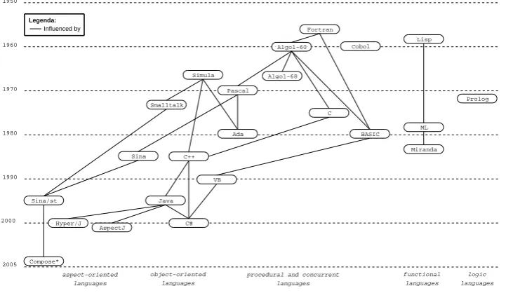
Fifteen years ago the dominant programming language paradigm was procedural pro-gramming. This paradigm is characterized by the use of statements that update state variables. Examples are Algol-like languages such as Pascal, C, and Fortran.
Other programming paradigms are the functional, logic, object-oriented, and aspect-oriented paradigms.Figure 1.1summarizes the dates and ancestry of several important languages [Wat90]. Every paradigm uses a different modularization mechanism for separating concerns into modules.
lan-1.1 Introduction University Twente
Figure 1.1: Dates and ancestry of several important languages
guages are entirely based on functions over lists and trees. Lisp and Miranda are examples of functional languages.
A logic language is based on a subset of mathematical logic. The computer is pro-grammed to infer relationships between values, rather than to compute output values from input values. Prolog is currently the most used logic language [Wat90].
A shortcoming of procedural programming is that global variables can potentially be accessed and updated by any part of the program. This can result in unmanageable programs because no module that accesses a global variable can be understood inde-pendently from other modules that also access that global variable.
The Object-Oriented Programming (OOP) paradigm improves modularity by encap-sulating data with methods inside objects. The data may only be accessed indirectly, by calling the associated methods. Although the concept appeared in the seventies, it took twenty years to become popular [Wat90]. The most well known object-oriented languages are C++, Java, C#, and Smalltalk.
The hard part about object-oriented design is decomposing a system into objects. The task is difficult because many factors come into play: encapsulation, granularity, de-pendency, adaptability, reusability, and others. They all influence the decomposition, often in conflicting ways [GHJV95].
University Twente 1.2 Traditional Approach
1 public class Add extends Calculation{
2
13 public void execute(int a, int b) {
14 trace.write("void Add.execute(int, int
8 public void update(int value){
9 trace.write("void CalcDisplay.update(
Listing 1.1: Modeling addition, display, and logging without using aspects
Aspect-Oriented Programming (AOP) is a paradigm that solves this problem.
AOP is commonly used in combination with OOP but can be applied to other paradigms as well. The following sections introduce an example to demonstrate the problems that may arise with OOP and show how AOP can solve this. Finally, we look at three particular AOP methodologies in more detail.
1.2
Traditional Approach
1.3 AOP Approach University Twente
From our example, we recognize two forms of crosscutting: code tanglingandcode scattering.
The addition and display concerns are implemented in classesAddandCalcDisplay respectively. Tracing is implemented in the classTracer, but also contains code in the other two classes (lines5,10,14, and20in (a) and2,5, and9in (b)). If a concern is implemented across several classes it is said to be scattered. In the example of Listing 1.1the tracing concern is scattered.
Usually a scattered concern involves codereplication. That is, the same code is imple-mented a number of times. In our example the classesAddandCalcDisplaycontain similar tracing code.
In classAdd the code for the addition and tracing concerns are intermixed. In class CalcDisplaythe code for the display and tracing concerns are intermixed. If more then one concern is implemented in a single class they are said to be tangled. In our example the addition and tracing concerns are tangled. Also display and tracing concerns are tangled. Crosscutting code has the following consequences:
Code is difficult to change
Changing a scattered concern requires us to modify the code in several places. Making modifications to a tangled concern class requires checking for side-effects with all existing crosscutting concerns;
Code is harder to reuse
To reuse an object in another system, it is necessary to either remove the tracing code or reuse the (same) tracer object in the new system;
Code is harder to understand
Tangled code makes it difficult to see which code belongs to which concern.
1.3
AOP Approach
To solve the problems with crosscutting, several techniques are being researched that attempt to increase the expressiveness of the OO paradigm. Aspect-Oriented Pro-gramming (AOP) introduces a modular structure, the aspect, to capture the location and behavior of crosscutting concerns. Examples of Aspect-Oriented languages are Sina, AspectJ, Hyper/J, and Compose
?
. A special syntax is used to specify aspects and the way in which they are combined with regular objects. The fundamental goals of AOP are twofold [GL03]: first to provide a mechanism to express concerns that crosscut other components. Second to use this description to allow for the separation of concerns.University Twente 1.3 AOP Composition
1 public class Add extends Calculation{
2 private int result;
10 public void execute(int a, int b) {
11 result = a + b;
2 Tracer trace = new Tracer();
3
Listing 1.2: Modeling addition, display, and logging with aspects
In the example ofListing 1.2the classAdddoes not contain any tracing code and only implements the addition concern. ClassCalcDisplayalso does not contain tracing code. In our example the tracing aspect contains all the tracing code. The pointcut tracedCallsspecifies at which locations tracing code is executed.
The crosscutting concern is explicitly captured in aspects instead of being embedded within the code of other objects. This has several advantages over the previous code.
Aspect code can be changed
Changing aspect code does not influence other concerns; Aspect code can be reused
The coupling of aspects is done by defining pointcuts. In theory, this low cou-pling allows for reuse. In practice reuse is still difficult;
Aspect code is easier to understand
A concern can be understood independent of other concerns; Aspect pluggability
Enabling or disabling concerns becomes possible.
1.3.1 AOP Composition
AOP composition can be either symmetric or asymmetric. In the symmetric approach every component can be composed with any other component. This approach is fol-lowed by e.g. Hyper/J.
1.3 Aspect Weaving University Twente
program is composed with the aspects. This approach is followed by e.g. AspectJ (covered in more detail in the next section).
1.3.2 Aspect Weaving
The integration of components and aspects is calledaspect weaving. There are three approaches to aspect weaving. The first and second approach rely on adding behavior in the program, either by weaving the aspect in the source code, or by weaving directly in the target language. The target language can be intermediate language (IL) or ma-chine code. Examples of IL are Java byte code and Common Intermediate Language (CIL). The remainder of this chapter considers only intermediate language targets. The third approach relies on adapting the virtual machine. Each method is explained briefly in the following sections.
1.3.2.1 Source Code Weaving
The source code weaver combines the original source with aspect code. It interprets the defined aspects and combines them with the original source, generating input for the native compiler. For the native compiler there is no difference between source code with and without aspects. Hereafter the compiler generates an intermediate or machine language output (depending on the compiler-type).
The advantages of using source code weaving are:
High-level source modification
Since all modifications are done at source code level, there is no need to know the target (output) language of the native compiler;
Aspect and original source optimization
First the aspects are woven into the source code and hereafter compiled by the native compiler. The produced target language has all the benefits of the native compiler optimization passes. However, optimizations specific to exploiting as-pect knowledge are not possible;
Native compiler portability
The native compiler can be replaced by any other compiler as long as it has the same input language. Replacing the compiler with a newer version or another target language can be done with little or no modification to the aspect weaver.
However, the drawbacks of source code weaving are:
Language dependency
Source code weaving is written explicitly for the syntax of the input language; Limited expressiveness
University Twente 1.3 Aspect Weaving
when using source code weaving, it is not possible to add multiple inheritance to a single inheritance language.
1.3.2.2 Intermediate Language Weaving
Weaving aspects through an intermediate language gives more control over the exe-cutable program and solves some issues as identified inSection 1.3.2.1on source code weaving. Weaving at this level allows for creating combinations of intermediate lan-guage constructs that can not be expressed at the source code level. Although IL can be hard to understand, IL weaving has several advantages over source code weaving:
Programming language independence
All compilers generating the target IL output can be used; More expressiveness
It is possible to create IL constructs that are not possible in the original program-ming language;
Source code independence
Can add aspects to programs and libraries without using the source code (which may not be available);
Adding aspects at load- or runtime
A special class loader or runtime environment can decide and do dynamic weav-ing. The aspect weaver adds a runtime environment into the program. How and when aspects can be added to the program depend on the implementation of the runtime environment.
However, IL weaving also has drawbacks that do not exist for source code weaving:
Hard to understand
Specific knowledge about the IL is needed; More error-prone
Compiler optimization may cause unexpected results. Compiler can remove code that breaks the attached aspect (e .g., inlining of methods).
1.3.2.3 Adapting the Virtual Machine
Adapting the virtual machine (VM) removes the need to weave aspects. This technique has the same advantages as intermediate language weaving and can also overcome some of its disadvantages as mentioned in Section 1.3.2.2. Aspects can be added without recompilation, redeployment, and restart of the application [PGA02;PAG03].
1.4 AOP Solutions University Twente
Dependency on adapted virtual machines
Using an adapted virtual machine requires that every system should be upgraded to that version;
Virtual machine optimization
People have spend a lot of time optimizing virtual machines. By modifying the virtual machine these optimizations should be revisited. Reintegrating changes introduced by newer versions of the original virtual machine, might have sub-stantial impact.
1.4
AOP Solutions
As the concept of AOP has been embraced as a useful extension to classic program-ming, different AOP solutions have been developed. Each solution has one or more im-plementations to demonstrate how the solution is to be used. As described by [EFB01] these differ primarily in:
How aspects are specified
Each technique uses its own aspect language to describe the concerns; Composition mechanism
Each technique provides its own composition mechanisms; Implementation mechanism
Whether components are determined statically at compile time or dynamically at run time, the support for verification of compositions, and the type of weaving. Use of decoupling
Should the writer of the main code be aware that aspects are applied to his code; Supported software processes
The overall process, techniques for reusability, analyzing aspect performance of aspects, is it possible to monitor performance, and is it possible to debug the aspects.
This section will give a short introduction to AspectJ [KHH+01] and Hyper-spaces [OT01], which together with Composition Filters [BA01] are three main AOP approaches.
1.4.1 AspectJ Approach
University Twente 1.4 AspectJ Approach
7 before() : traceMethods {
8 log.write("Entering " + thisJointPoint.getSignature());
9 }
10
11 after() : traceMethods {
12 log.write("Exiting " + thisJointPoint.getSignature());
13 }
14 }
Listing 1.3: Example of dynamic crosscutting in AspectJ
it, build by several research groups. There are various projects that are porting AspectJ to other languages, resulting in tools such as AspectR and AspectC.
One of the main goals in the design of AspectJ is to make it a compatible extension to Java. AspectJ tries to be compatible in four ways:
Upward compatibility
All legal Java programs must be legal AspectJ programs; Platform compatibility
All legal AspectJ programs must run on standard Java virtual machines; Tool compatibility
It must be possible to extend existing tools to support AspectJ in a natural way; this includes IDEs, documentation tools and design tools;
Programmer compatibility
Programming with AspectJ must feel like a natural extension of programming with Java.
AspectJ extends Java with support for two kinds of crosscutting functionality. The first allows defining additional behavior to run at certain well-defined points in the execu-tion of the program and is called thedynamic crosscutting mechanism. The other is called thestatic crosscutting mechanismand allows modifying the static structure of classes (methods and relationships between classes). The units of crosscutting imple-mentation are called aspects. An example of an aspect specified in AspectJ is shown inListing 1.3.
The points in the execution of a program where the crosscutting behavior is inserted are calledjoinpoints. Apointcuthas a set of joinpoints. InListing 1.3istraceMethods an example of a pointcut definition. The pointcut includes all executions of any method that is in a class contained by packageedu.utwente.trese.
1.4 Hyperspaces Approach University Twente
1 aspect StaticCrosscuttingExample {
2 private int Log.trace(String traceMsg) {
3 Log.write(" --- MARK --- " + traceMsg);
4 }
5 }
Listing 1.4: Example of static crosscutting in AspectJ
afterandaroundadvice that specifies where the additional code is to be inserted. In the example both before and after advice are declared to run at the joinpoints specified by thetraceMethodspointcut.
Aspects can contain anything permitted in class declarations including definitions of pointcuts, advice and static crosscutting. For example, static crosscutting allows a programmer to add fields and methods to certain classes as shown inListing 1.4.
The shown construct is called inter-type member declaration and adds a methodtrace to classLog. Other forms of inter-type declarations allow developers to declare the parents of classes (superclasses and realized interfaces), declare where exceptions need to be thrown, and allow a developer to define the precedence among aspects.
With its variety of possibilities AspectJ can be considered a useful approach for real-izing software requirements.
1.4.2 Hyperspaces Approach
TheHyperspacesapproach is developed by H. Ossher and P. Tarr at the IBM T.J. Wat-son Research Center. The Hyperspaces approach adopts the principle of multi-dimensional separation of concerns [OT01], which involves:
• Multiple, arbitrary dimensions of concerns;
• Simultaneous separation along these dimensions;
• Ability to dynamically handle new concerns and new dimensions of concern as they arise throughout the software life cycle;
• Overlapping and interacting concerns. It is appealing to think of many concerns as independent or orthogonal, but they rarely are in practice.
University Twente 1.4 Hyperspaces Approach
1 Hyperspace Pacman
2 class edu.utwente.trese.pacman.*;
Listing 1.5: Creation of a hyperspace
1 package edu.utwente.trese.pacman: Feature.Kernel
2 operation trace: Feature.Logging
3 operation debug: Feature.Debugging
Listing 1.6: Specification of concern mappings
1 hypermodule Pacman_Without_Debugging
2 hyperslices: Feature.Kernel, Feature.Logging;
3 relationships: mergeByName;
4 end hypermodule;
Listing 1.7: Defining a hypermodule
As a first step, developers create hyperspaces by specifying a set of Java class files that contain the code units that populate the hyperspace. To do this is, you create a hyperspace specification, as demonstrated inListing 1.5.
Hyper/J will automatically create a hyperspace with one dimension—the class file di-mension. A dimension of concern is a set of concerns that are disjoint. The initial hyperspace will contain all units within the specified package. To create a new di-mension you can specify concern mappings, which describe how existing units in the hyperspace relate to concerns in that dimension, as demonstrated inListing 1.6.
The first line indicates that, by default, all of the units contained within the package edu.utwente.trese.pacmanaddress the kernel concern of the feature dimension. The other mappings specify that any method named trace or debug address the logging and debugging concern respectively. These later mappings override the first one.
Hypermodules are based on concerns and consist of two parts. The first part specifies a set of hyperslices in terms of the concerns identified in the concern matrix. The second part specifies the integration relationships between the hyperslices. A hyperspace can contain several hypermodules realizing different modularizations of the same units. Systems can be composed in many ways from these hypermodules.
1.4 Composition Filters University Twente
The most important feature of the hyperspaces approach is the support for on-demand remodularisation: the ability to extract hyperslices to encapsulate concerns that were not separated in the original code. Which makes hyperspaces especially useful for evolution of existing software.
1.4.3 Composition Filters
Composition Filtersis developed by M. Aks¸it and L. Bergmans at the TRESE group, which is a part of the Department of Computer Science of the University of Twente, The Netherlands. The composition filters (CF) model predates aspect-oriented pro-gramming. It started out as an extension to the object-oriented model and evolved into an aspect-oriented model. The current implementation of CF is Compose
?
, which covers .NET, Java, and C.One of the key elements of CF is themessage, a message is the interaction between objects, for instance a method call. In object-oriented programming the message is considered an abstract concept. In the implementations of CF it is therefore necessary to reify the message. Thisreified messagecontains properties, like where it is send to and where it came from.
The concept of CF is that messages that enter and exit an object can be intercepted and manipulated, modifying the original flow of the message. To do so, a layer called theinterface partis introduced in the CF model, this layer can have several properties. The interface part can be placed on an object, which behavior needs to be altered, and this object is referred to asinner.
Chapter
2
Compose
?
“The difficult part of composition filters is understanding its simplicity.” Lodewijk Bergmans
Compose
?
is an implementation of the composition filters approach. There are three target environments: the .NET, Java, and C. This chapter is organized as follows, first the evolution of Composition Filters and its implementations are described, followed by an explanation of the Compose?
language and a demonstrating example. In the third section, the Compose?
architecture is explained, followed by a description of the features specific to Compose?
.2.1
Evolution of Composition Filters
Compose
?
is the result of many years of research and experimentation. The following time line gives an overview of what has been done in the years before and during the Compose?
project.1985 The first version of Sina is developed by Mehmet Aks¸it. This version of Sina contains a preliminary version of the composition filters concept called semantic networks. The semantic network construction serves as an exten-sion to objects, such as classes, messages, or instances. These objects can be configured to form other objects such as classes from which instances can be created. The object manager takes care of synchronization and message processing of an object. The semantic network construction can express key concepts like delegation, reflection, and synchronization [Koo95].
2.2 Composition Filters in Compose
?
University Twentedeclarative specifications and the interface predicate construct is added. 1991 The interface predicates are replaced by the dispatch filter, and the wait
fil-ter manages the synchronization functions of the object manager. Message reflection and real-time specifications are handled by the meta filter and the real-time filter [Ber94].
1995 The Sina language with Composition Filters is implemented using Small-talk [Koo95]. The implementation supports most of the filter types. In the same year, a preprocessor providing C++ with support for Composition Fil-ters is implemented [Gla95].
1999 The composition filters language ComposeJ [Wic99] is developed and im-plemented. The implementation consists of a preprocessor capable of trans-lating composition filter specifications into the Java language.
2001 ConcernJ is implemented as part of a M. Sc. thesis [Sal01]. ConcernJ adds the notion of superimposition to Composition Filters. This allows for reuse of the filter modules and to facilitate crosscutting concerns.
2003 The start of the Compose
?
project, the project is described in further detail in this chapter.2004 The first release of Compose
?
, based on .NET. 2005 The start of the Java port of Compose?
. 2006 Porting Compose?
to C is started.2.2
Composition Filters in Compose
?
1 concern {
University Twente 2.2 Composition Filters in Compose
?
name. A superimposition part specifies which filter modules, annotations, conditions, and methods are superimposed on which objects. An implementation part contains the class implementation of a concern. How these parts are placed in a concern is shown inListing 2.1.
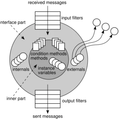
Figure 2.1: Components of the composition filters model
The working of a filter module is depicted inFigure 2.1. A filter module can contain input and output filters. The difference between these two sets of filters is that the first is used to filter on incoming messages, while the second is used to filter on outgoing messages. The return of a method is not considered an outgoing message. A filter has three parts: a filter identifier, a filter type, and one or more filter elements. A filter element exists out of an optional condition part, a matching part, and a substitution part. These parts are shown below:
identif ier
2.2 Composition Filters in Compose
?
University TwenteAt the moment there are four basic filter types defined in Compose
?
. It is, however, possible to write custom filter types.Dispatch If the message is accepted, it is dispatched to the specified target of the message, otherwise the message continues to the subsequent filter. This filter type can only be used for input filters;
Send If the message is accepted, it is sent to the specified target of the message, otherwise the message continues to the subsequent filter. This filter type can only be used for output filters;
Error If the filter rejects the message, it raises an exception, otherwise the mes-sage continues to the next filter in the set;
Meta If the message is accepted, the message is sent as a parameter of another meta message to an internal or external object, otherwise the message just continues to the next filter. The object that receives the meta message can observe and manipulate the message and can re-activate the execution of the message.
The identifier pacmanIsEvil, used in the condition part, must be declared in the conditions section of a filter module. Targets that are used in a filter can be declared as internal or external. An internal is an object that is unique for each instance of a filter module, while an external is an object that is shared between filter modules.
Filter modules are superimposed on classes using filter module binding, which spec-ifies a selection of objects on the one side, and a filter module on the other side. The selection is specified in a selector definition. This selector definition uses predicates to select objects, such asisClassWithNameInList,isNamespaceWithName, and namespaceHasClass. In addition to filter modules, it is possible to bind conditions, methods, and annotations to classes using superimposition.
University Twente 2.3 Demonstrating Example
2.3
Demonstrating Example
To illustrate the Compose
?
toolset, this section introduces aPacman example. The Pacman game is a classic arcade game in which the user, represented by pacman, moves in a maze to eat vitamins. Meanwhile, a number of ghosts try to catch and eat pacman. There are, however, four mega vitamins in the maze that make pacman evil. In its evil state, pacman can eat ghosts. A simple list of requirements for the Pacman game is briefly discussed here:• The number of lives taken from pacman when eaten by a ghost;
• A game should end when pacman has no more lives;
• The score of a game should increase when pacman eats a vitamin or a ghost;
• A user should be able to use a keyboard to move pacman around the maze;
• Ghosts should know whether pacman is evil or not;
• Ghosts should know where pacman is located;
• Ghosts should, depending on the state of pacman, hunt or flee from pacman.
2.3.1 Initial Object-Oriented Design
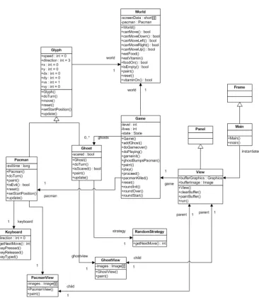
Figure 2.2shows an initial object-oriented design for the Pacman game. Note that this UML class diagram does not show the trivial accessors. The classes in this diagram are:
Game This class encapsulates the control flow and controls the state of a game;
Ghost This class is a representation of a ghost chasing pacman. Its main attribute is a property that indicates whether it is scared or not (depending on the evil state of pacman);
GhostView This class is responsible for painting ghosts;
Glyph This is the superclass of all mobile objects (pacman and ghosts). It contains common information like direction and speed; Keyboard This class accepts all keyboard input and makes it available to
pacman;
Main This is the entry point of a game;
Pacman This is a representation of the user controlled element in the game. Its main attribute is a property that indicates whether pacman is evil or not;
PacmanView This class is responsible for painting pacman;
RandomStrategy By using this strategy, ghosts move in random directions; View This class is responsible for painting a maze;
2.3 Initial Object-Oriented Design University Twente
University Twente 2.3 Completing the Pacman Example
1 concern DynamicScoring in Pacman {
2 filtermodule dynamicscoring {
3 externals
4 score : pacman.Score = pacman.Score.instance();
5 inputfilters
6 score_filter : Meta = {[*.eatFood] score.eatFood,
7 [*.eatGhost] score.eatGhost,
14 scoring = { C | isClassWithNameInList(C, [’pacman.World’,
15 ’pacman.Game’, ’pacman.Main’]) };
16 filtermodules
17 scoring <- dynamicscoring;
18 }
19 }
Listing 2.2:DynamicScoringconcern in Compose
?
2.3.2 Completing the Pacman Example
The initial object-oriented design, described in the previous section, does not imple-ment all the stated system requireimple-ments. The missing requireimple-ments are:
• The application does not maintain a score for the user;
• Ghosts move in random directions instead of chasing or fleeing from pacman.
In the next sections, we describe why and how to implement these requirements in the Compose
?
language.2.3.2.1 Implementation of Scoring
The first system requirement that we need to add to the existing Pacman game is scor-ing. This concern involves a number of events. First, the score should be set to zero when a game starts. Second, the score should be updated whenever pacman eats a vita-min, mega vitamin or ghost. And finally, the score itself has to be painted on the maze canvas to relay it back to the user. These events scatter over multiple classes: Game (initializing score),World(updating score),Main(painting score). Thus scoring is an example of a crosscutting concern.
2.4 Compose
?
Architecture University TwenteThis concern definition is calledDynamicScoring(line 1) and contains two parts. The first part is the declaration of a filter module calleddynamicscoring(lines2– 11). This filter module contains onemeta filter calledscore_filter(line6). This filter intercepts five relevant calls and sends the message in a reified form to an in-stance of classScore. The final part of the concern definition is the superimposition part (lines12–18). This part defines that the filter moduledynamicscoringis to be superimposed on the classesWorld,GameandMain.
The final part of the scoring concern is the so-calledimplementation part. This part is defined by a classScore. Listing 2.3shows an example implementation of class Score. Instances of this class receive the messages sent byscore_filterand sub-sequently perform the events related to the scoring concern. In this way, all scoring events are encapsulated in one class and one Compose
?
concern definition.2.3.2.2 Implementation of Dynamic Strategy
The last system requirement that we need to implement is the dynamic strategy of ghosts. This means that a ghost should, depending on the state of pacman, hunt or flee from pacman. We can implement this concern by using the strategy design pattern. However, in this way, we need to modify the existing code. This is not the case when we use Compose
?
dispatch filters.Listing 2.4demonstrates this.This concern uses dispatch filters to intercept calls to methodgetNextMove of the class RandomStrategy. These calls are redirected to either StalkerStrategy. getNextMoveorFleeStrategy.getNextMove. If pacman is not evil, the inter-cepted call matches the first filter, which dispatches the interinter-cepted call to method StalkerStrategy.getNextMove(line9). Otherwise, the intercepted call matches the second filter, which dispatches the intercepted call to method FleeStrategy. getNextMove(line11).
2.4
Compose
?
Architecture
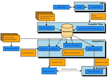
An overview of the Compose
?
architecture is illustrated inFigure 2.3. The Compose?
architecture can be divided in four layers [Nag06]: IDE, compile time, adaptation, and runtime.2.4.1 Integrated Development Environment
University Twente 2.4 Integrated Development Environment
1 public class Score
2 {
3 private int score = -100;
4 private static Score theScore = null;
5 private Label label = new java.awt.Label("Score: 0");
6
7 private Score() {}
8
9 public static Score instance() {
10 if(theScore == null) {
16 public void initScore(ReifiedMessage rm) {
17 this.score = 0;
18 label.setText("Score: "+score);
19 }
20
21 public void eatGhost(ReifiedMessage rm) {
22 score += 25;
23 label.setText("Score: "+score);
24 }
25
26 public void eatVitamin(ReifiedMessage rm) {
27 score += 15;
28 label.setText("Score: "+score);
29 }
30
31 public void eatFood(ReifiedMessage rm) {
32 score += 5;
33 label.setText("Score: "+score);
34 }
35
36 public void setupLabel(ReifiedMessage rm) {
37 rm.proceed();
38 label = new Label("Score: 0");
39 label.setSize(15*View.BLOCKSIZE+20,15*View.BLOCKSIZE);
2.4 Integrated Development Environment University Twente
1 concern DynamicStrategy in Pacman {
2 filtermodule dynamicstrategy {
3 internals
4 stalk_strategy : pacman.Strategies.StalkerStrategy;
5 flee_strategy : pacman.Strategies.FleeStrategy;
6 conditions
7 pacmanIsEvil : pacman.Pacman.isEvil();
8 inputfilters
9 stalker_filter : Dispatch = {!pacmanIsEvil =>
10 [*.getNextMove] stalk_strategy.getNextMove};
11 flee_filter : Dispatch = {
12 [*.getNextMove] flee_strategy.getNextMove}
13 }
14 superimposition {
15 selectors
16 random = { C | isClassWithName(C,
17 ’pacman.Strategies.RandomStrategy’) };
18 filtermodules
19 random <- dynamicstrategy;
20 }
21 }
Listing 2.4:DynamicStrategyconcern in Compose
?
University Twente 2.4 Compile Time
The creation of a build configuration can be done manually or by using a plug-in. Examples of these plug-ins are the Visual Studio add-in for Compose
?
/.NET and the Eclipse plug-in for Compose?
/J and Compose?
/C.2.4.2 Compile Time
The compile time layer is platform independent and reasons about the correctness of the composition filter implementation with respect to the program which allows the target program to be build by the adaptation.
The compile time ‘pre-processes’ the composition filter specifications by parsing the specification, resolving the references, and checking its consistency. To provide an ex-tensible architecture to facilitate this process a blackboard architecture is chosen. This means that the compile time uses a general knowledgebase that is called the ‘reposi-tory’. This knowledgebase contains the structure and metadata of the program which different modules can execute their activities on. Examples of modules within analysis and validation are the three modules SANE, LOLA and FILTH. These three modules are responsible for (some) of the analysis and validation of the super imposition and its selectors.
2.4.3 Adaptation
The adaptation layer consists of the program manipulation, harvester, and code gen-erator. These components connect the platform independent compile time to the tar-get platform. The harvester is responsible for gathering the structure and the anno-tations within the source program and adding this information to the knowledgebase. The code generation generates a reduced copy of the knowledgebase and the weaving specification. This weaving specification is then used by the weaver contained by the program manipulation to weave in the calls to the runtime into the target program. The end result of the adaptation the target program which interfaces wit the runtime.
2.4.4 Runtime
2.5 Platforms University Twente
2.5
Platforms
The composition filters concept of Compose
?
can be applied to any programming language, given that certain assumptions are met. Currently, Compose?
supports three platforms: .NET, Java and C. For each platform different tools are used for compilation and weaving. They all share the same platform independent compile-time.Compose
?
/.NET targets the .NET platform and is the oldest implementation of Compose?
. Its weaver operates on CIL byte code. Compose?
/.NET is program-ming language independent as long as the programprogram-ming language can be compiled to CIL code. An add-in for Visual Studio is provided for ease of development. Compose?
/J targets the Java platform and provides a plug-in for integration with Eclipse. Compose?
/C contains support for the C programming language. The im-plementation is different from the Java and .NET counterparts, because it does not have a run-time environment. The filter logic is woven directly in the source code. Because the language C is not based on objects, filters are woven on functions based on membership of sets of functions. Like the Java platform, Compose?
/C provides a plug-in for Eclipse.2.6
Features Specific to Compose
?
The Composition Filters approach uses a restricted (pattern matching) language to define filters. This language makes it possible to reason about the semantics of the concern. Compose
?
offers three features that use this possibility, which originate in more control and correctness over an application under construction. These features are:Ordering of filter modules
It is possible to specify how the superimposition of filter modules should be or-dered. Ordering constraints can be specified in a fixed, conditional, or partial manner. A fixed ordering can be calculated exactly, whereas a conditional or-dering is dependent on the result of filter execution and therefore evaluated at runtime. When there are multiple valid orderings of filtermodules on a join-point, partial ordering constraints can be applied to reduce this number. These constraints can be declared in the concern definition;
Filter consistency checking
University Twente 2.6 Features Specific to Compose
?
Reason about semantic problems
When multiple pieces of advice are added to the same joinpoint, Compose
?
can reason about problems that may occur. An example of such a conflict is the situation where a real-time filter is followed by a wait filter. Because the wait filter can wait indefinitely, the real-time property imposed by the real-time filter may be violated.The above mentioned conflict analyzers all work on the assumption that the behavior of every filter is well-defined. This is not the case for the meta filter, its user-undefined, and therefore unpredictable, behavior poses a problem to the analysis tools.
Furthermore, Compose
?
is extended with features that enhance the usability. These features are briefly described below:Integrated Development Environment support
The Compose
?
implementations all have a IDE plug-in; Compose?
/.NET for Visual Studio, Compose?
/J and Compose?
/C for Eclipse;Debugging support
The debugger shows the flow of messages through the filters. It is possible to place breakpoints to view the state of the filters;
Incremental building process
When a project is build and not all the modules are changed, incremental build-ing saves time.
Some language properties of Compose
?
can also be seen as features, being:Language independent concerns
A Compose
?
concern can be used for all the Compose?
platforms, because the composition filters approach is language independent;Reusable concerns
The concerns are easy to reuse, through the dynamic filter modules and the se-lector language;
Expressive selector language
Program elements of an implementation language can be used to select a set of objects to superimpose on;
Support for annotations
Chapter
3
Introduction to the .NET Framework
“The best way to prepare [to be a programmer] is to write programs, and to study great programs that other people have written. In my case, I went to the garbage cans at the Computer Science Center and fished out listings of their operating system.” William Henry Gates III
This chapter gives an introduction to the .NET Framework of Microsoft. First, the architecture of the .NET Framework is introduced. This section includes terms like the Common Language Runtime, the .NET Class Library, the Common Language In-frastructure and the Intermediate Language. These are discussed in more detail in the sections following the architecture.
3.1
Introduction
Microsoft defines [Mic05] .NET as follows; “.NET is the Microsoft Web services strat-egy to connect information, people, systems, and devices through software.”. There are different .NET technologies in various Microsoft products providing the capabilities to create solutions using web services. Web services are small, reusable applications that help computers from many different operating system platforms work together by exchanging messages. Based on industry standards like XML (Extensible Markup Language), SOAP (Simple Object Access Protocol), and WSDL (Web Services De-scription Language) they provide a platform and language independent way to com-municate.
inte-3.2 Architecture of the .NET Framework University Twente
grated development environment, they provide the developer tools to create programs for .NET.
Many companies are largely dependent on the .NET Framework, but need or want to use AOP. Currently there is no direct support for this in the Framework. The Compose
?
/.NET project is addressing these needs with its implementation of the Composition Filters approach for the .NET Framework.This specific Compose
?
version for .NET has two main goals. First, it combines the .NET Framework with AOP through Composition Filters. Second, Compose?
offers superimposition in a language independent manner. The .NET Framework supports multiple languages and is, as such, suitable for this purpose. Composition Filters are an extension of the object-oriented mechanism as offered by .NET, hence the imple-mentation is not restricted to any specific object-oriented language.3.2
Architecture of the .NET Framework
The .NET Framework is Microsoft’s platform for building, deploying, and running Web Services and applications. It is designed from scratch and has a consistent API providing support for component-based programs and Internet programming. This new Application Programming Interface (API) has become an integral component of Windows. The .NET Framework was designed to fulfill the following objec-tives [Mic03b]:
Consistency
Allow object code to be stored and executed locally, executed locally but Internet-distributed, or executed remotely and to make the developer experience consistent across a wide variety of types of applications, such as Windows-based applications and Web-based applications;
Operability
The ease of operation is enhanced by minimizing version conflicts and providing better software deployment support;
Security
All the code is executed safely, including code created by an unknown or semi-trusted third party;
Efficiency
The .NET Framework compiles applications to machine code before running thus eliminating the performance problems of scripted or interpreted environ-ments;
Interoperability
University Twente 3.2 Architecture of the .NET Framework
Figure 3.1: Context of the .NET Framework (Modified) [Mic03b]
The .NET Framework consists of two main components [Mic03b]: the Common Lan-guage Runtime (CLR, simply called the .NET Runtime or Runtime for short) and the .NET Framework Class Library (FCL). The CLR is the foundation of the .NET Framework, executing the code and providing the core services such as memory man-agement, thread management and exception handling. The CLR is described in more detail inSection 3.3. The class library, the other main component of the .NET Frame-work, is a comprehensive, object-oriented collection of reusable types that can be used to develop applications ranging from traditional command-line or graphical user inter-face (GUI) applications to applications such as Web Forms and XML Web services. Section 3.5describes the class libraries in more detail.
The code run by the runtime is in a format called Common Intermediate Language (CIL), further explained inSection 3.6. The Common Language Infrastructure (CLI) is an open specification that describes the executable code and runtime environment that form the core of the Microsoft .NET Framework.Section 3.4tells more about this specification.
Figure 3.1shows the relationship of the .NET Framework to other applications and to the complete system. The two parts, the class library and the runtime, are managed, i .e., applications managed during execution. The operating system is in the core, managed and unmanaged applications operate on the hardware. The runtime can us other object libraries and the class library, but the other libraries can use the same class library them self.
3.2 Version 2.0 of .NET University Twente
3.2.1 Version 2.0 of .NET
In November 2005, Microsoft released a successor of the .NET Framework. Major changes are the support for generics, the addition of nullable types, 64 bit support, improvements in the garbage collector, new security features and more network func-tionality.
Generics make it possible to declare and define classes, structures, interfaces, methods and delegates with unspecified or generic type parameters instead of specific types. When the generic is used, the actual type is specified. This allows for type-safety at compile-time. Without generics, the use of casting or boxing and unboxing decreases performance. By using a generic type, the risks and costs of these operations is re-duced.
Nullable types allow a value type to have a normal value or a null value. This null value can be useful for indicating that a variable has no defined value because the information is not currently available.
Besides changes in the Framework, there are also improvements in the four main Mi-crosoft .NET programming languages (C#, VB.NET, J# and C++). The language el-ements are now almost equal for all languages. For instance, additions to the Visual Basic language are the support for unsigned values and new operators and additions to the C# language include the ability to define anonymous methods thus eliminating the need to create a separate method.
A new Visual Studio 2005 edition was released to support the new Framework and functionalities to create various types of applications.
3.3
Common Language Runtime
The Common Language Runtime executes code and provides core services. These core services are memory management, thread execution, code safety verification and compilation. Apart from providing services, the CLR also enforces code access se-curity and code robustness. Code access sese-curity is enforced by providing varying degrees of trust to components, based on a number of factors, e .g., the origin of a component. This way, a managed component might or might not be able to perform sensitive functions, like file-access or registry-access. By implementing a strict type-and-code-verification infrastructure, called the Common Type System (CTS), the CLR enforces code robustness. Basically there are two types of code;
Managed
University Twente 3.3 Java VM vs .NET CLR
of specifications, the Common Language Specification (CLS). The code is run by the CLR and is typically stored in an intermediate language format. This platform independent intermediate language is officially known as Common In-termediate Language (CILSection 3.6) [Wat00].
Unmanaged
Unmanaged code is not managed by the CLR. It is stored in the native machine language and is not run by the runtime but directly by the processor.
All language compilers (targeting the CLR) generate managed code (CIL) that con-forms to the CTS.
At runtime, the CLR is responsible for generating platform specific code, which can actually be executed on the target platform. Compiling from CIL to the native ma-chine language of the platform is executed by the just-in-time (JIT) compiler. Be-cause of this language independent layer it allows the development of CLRs for any platform, creating a true interoperability infrastructure [Wat00]. The .NET Runtime from Microsoft is actually a specific CLR implementation for the Windows platform. Microsoft has released the.NET Compact Framework especially for devices such as personal digital assistants (PDAs) and mobile phones. The .NET Compact Framework contains a subset of the normal .NET Framework and allows .NET developer to write mobile applications. Components can be exchanged and web services can be used so an easier interoperability between mobile devices and workstations/servers can be implemented [Mic03a].
At the time of writing, the .NET Framework is the only advanced Common Language Infrastructure (CLI) implementation available. A shared-source1 implementation of the CLI for research and teaching purposes was made available by Microsoft in 2002 under the name Rotor [Stu02]. In 2006 Microsoft released an updated version of Rotor for the .NET platform version two. Also Ximian is working on an open source imple-mentation of the CLI under the name Mono2, targeting both Unix/Linux and Windows platforms. Another, somewhat different approach, is called Plataforma.NET3and aims to be a hardware implementation of the CLR, so that CIL code can be run natively.
3.3.1 Java VM vs .NET CLR
There are many similarities between Java and .NET technology. This is not strange, because both products serve the same market.
Both Java and .NET are based on a runtime environment and an extensive development framework. These development frameworks provide largely the same functionality for both Java and .NET. The most obvious difference between them is lack of language independence in Java. While Java’s strategy is ‘One language for all platforms’ the
1Only non-commercial purposes are allowed. 2
http://www.go-mono.com/
3
3.4 Common Language Infrastructure University Twente
.NET philosophy is ‘All languages on one platform’. However these philosophies are not as strict as they seem. As noted inSection 3.5there is no technical obstacle for other platforms to implement the .NET Framework. There are compilers for non-Java languages like Jython (Python) [Jyt] and WebADA [Ada96] available for the JVM. Thus, the JVM in its current state, has difficulties supporting such a vast array of languages as the CLR. However, the multiple language support in .NET is not optimal and has been the target of some criticism.
Although the JVM and the CLR provide the same basic features they differ in some ways. While both CLR and the modern JVM use JIT (Just In Time) compilation the CLR can directly access native functions. This means that with the JVM an indirect mapping is needed to interface directly with the operating system.
3.4
Common Language Infrastructure
The entire CLI has been documented, standardized and approved [Int02] by the Eu-ropean association for standardizing information and communication systems, Ecma International1. Benefits of this CLI for developers and end-users are:
• Most high level programming languages can easily be mapped onto the Com-mon Type System (CTS);
• The same application will run on different CLI implementations;
• Cross-programming language integration, if the code strictly conforms to the Common Language Specification (CLS);
• Different CLI implementations can communicate with each other, providing ap-plications with easy cross-platform communication means.
This interoperability and portability is, for instance, achieved by using a standardized meta data and intermediate language (CIL) scheme as the storage and distribution format for applications. In other words, (almost) any programming language can be mapped to CIL, which in turn can be mapped to any native machine language.
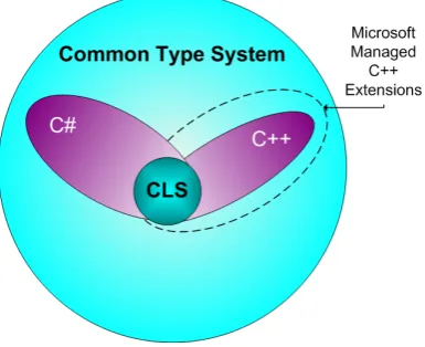
The Common Language Specification is a subset of the Common Type System, and defines the basic set of language features that all .NET languages should adhere to. In this way, the CLS helps to enhance and ensure language interoperability by defining a set of features that are available in a wide variety of languages. The CLS was designed to include all the language constructs that are commonly needed by developers (e .g., naming conventions, common primitive types), but no more than most languages are able to support [Mic03c]. Figure 3.2shows the relationships between the CTS, the CLS, and the types available in C++ and C#. In this way the standardized CLI
pro-1
University Twente 3.5 Framework Class Library
Figure 3.2: Relationships in the CTS
vides, in theory1, a true cross-language and cross-platform development and runtime environment.
To attract a large number of developers for the .NET Framework, Microsoft has re-leased CIL compilers for C++, C#, J#, and VB.NET. In addition, third-party vendors and open-source projects also released compilers targeting the .NET Framework, such as Delphi.NET, Perl.NET, IronPython, and Eiffel.NET. These programming languages cover a wide-range of different programming paradigms, such as classic imperative, object-oriented, scripting, and declarative languages. This wide coverage demonstrates the power of the standardized CLI.
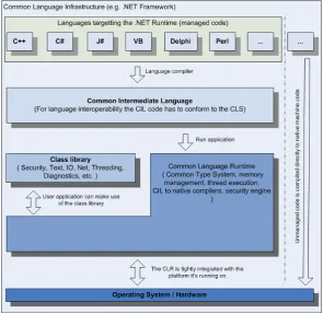
Figure 3.3shows the relationships between all the main components of the CLI. The top of the figure shows the different programming languages with compiler support for the CLI. Because the compiled code is stored and distributed in the Common Interme-diate Language format, the code can run on any CLR. For cross-language usage this code has to comply with the CLS. Any application can use the class library (the FCL) for common and specialized programming tasks.
3.5
Framework Class Library
The .NET Framework class library is a comprehensive collection of object-oriented reusable types for the CLR. This library is the foundation on which all the .NET ap-plications are built. It is object oriented and provides integration of third-party com-ponents with the classes in the .NET Framework. Developers can use comcom-ponents provided by the .NET Framework, other developers and their own components. A wide range of common programming tasks (e .g., string management, data collection, reflection, graphics, database connectivity or file access) can be accomplished easily
1Unfortunately Microsoft did not submit all the framework classes for approval and at the time of
3.6 Common Intermediate Language University Twente
Figure 3.3: Main components of the CLI and their relationships. The right hand side of the figure shows the difference between managed code and unmanaged code.
by using the class library. Also a great number of specialized development tasks are extensively supported, like:
• Console applications;
• Windows GUI applications (Windows Forms);
• Web applications (Web Forms);
• XML Web services;
• Windows services.
All the types in this framework are CLS compliant and can therefore be used from any programming language whose compiler conforms to the Common Language Specifi-cation (CLS).
3.6
Common Intermediate Language
University Twente 3.6 Common Intermediate Language
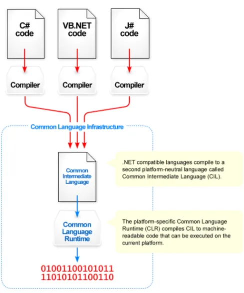
Figure 3.4: From source code to machine code
A .NET compiler generates amanaged modulewhich is an executable designed to be run by the CLR [Pro02]. There are four main elements inside a managed module:
• A Windows Portable Executable (PE) file header;
• A CLR header containing important information about the module, such as the location of its CIL and metadata;
• Metadata describing everything inside the module and its external dependencies;
• The CIL instructions generated from the source code.
The Portable Executable file header allows the user to start the executable. This small piece of code will initiate the just-in-time compiler which compiles the CIL instruc-tions to native code when needed, while using the metadata for extra information about the program. This native code is machine dependent while the original IL code is still machine independent. This way the same IL code can be JIT-compiled and executed on any supported architecture. The CLR cannot use the managed module directly but needs an assembly.
assem-3.6 Common Intermediate Language University Twente
bly describing not only the name, culture and version of the assembly but also the references to other files in the assembly and security requests.
The CIL is an object oriented assembly language with around 100 different instructions called OpCodes. It is stack-based, meaning objects are placed on an evaluation stack before the execution of an operation, and when applicable, the result can be found on the stack after the operation. For instance, when adding two numbers, first those numbers have to be placed onto the stack, second the add operation is called and finally the result can be retrieved from the stack.
1 .assembly AddExample {}
2
3 .method static public void main() il managed
4 {
5 .entrypoint // entry point of the application
6 .maxstack 2
14 // Call static System.Console.Writeline function
15 // (function pops integer from the stack)
16 call void [mscorlib]System.Console::WriteLine(int32)
17
18 ret
19 }
Listing 3.1: Adding example in IL code
To illustrate how to create a .NET program in IL code we use the previous example of adding two numbers and show the result. InListing 3.1a new assembly is created with the name AddExample. In this assembly a functionmainis declared as the starting point (entrypoint) of this assembly. Themaxstackcommand indicates there can be a maximum of two objects on the stack and this is enough for the example method. Next, the values 3 and 7 are placed onto the stack. Theaddoperation is called and the results stays on the stack. The methodWriteLinefrom the .NET Framework Class Library is called. This method resides inside theConsoleclass placed in theSystem assembly. It expects one parameter with aint32as its type that will be retrieved from the stack. The calloperation will transfer the control flow to this method passing along the parameters as objects on the stack. TheWriteLinemethod does not return a value. Theretoperation returns the control flow from the main method to the calling method, in this case the runtime. This will exit the program.
To be able to run this example, we need to compile the IL code to bytecode where each OpCode is represented as one byte. To compile this example, save it as a text file and run theILASMcompiler with as parameter the filename. This will produce an executable runnable on all the platforms where the .NET Framework is installed.
University Twente 3.6 Common Intermediate Language
language such as C# or VB.NET. For instance, the same example in C# code is shown inListing 3.2 and the VB.NET version is listed in Listing 3.3. When this code is compiled to IL, it will look like the code inListing 3.1.
1 public static void main()
2 {
3 Console.WriteLine((int) (3 + 7));
4 }
Listing 3.2: Adding example in the C# language
1 Public Shared Sub main()
2 Console.WriteLine(CType((3 + 7), Integer))
3 End Sub
Chapter
4
Problem Statement
“If debugging is the process of removing bugs, then programming must be the process of putting them in.” Edsger Dijkstra
This chapter explains the problems associated with the debugging of Aspect-oriented programs which this thesis addresses. First, the concept of debugging is introduced, which includes terms like bug, fault and failure. Second, the difficulties and ap-proaches in debugging software programs are addressed. Third, the difficulties in de-bugging Aspect-oriented programs are highlighted. Finally, the problem addressed in this thesis is formulated.
4.1
Bug Anatomy
Computer programs are build by compilers, from source code into atarget program. This target program is then deployed and executed. Because computer programs are complex, developers make programming errors in the source code, calledbugs. We distinguish two kinds of bugs; syntactic and semantic.
Syntactic bugs are a violation of the syntax of a language. An example of a syntactic bug in the English language would be;
I are going to my mother.
4.2 Difficulties in debugging software programs University Twente
containing syntactic bugs. This means that detection of syntactic bugs can be done by using the compiler.
A semantic bug is an incorrect or unintended meaning of the specification. An example of a semantic bug in the English language is;
My hamster just drove a car to Jupiter.
While most English speakers would agree that the sentence is syntactical correct, its meaning could be questioned. Since a semantic bug does not violate the syntax of a language it can therefore not be found by just validating the syntax. Therefore a more detailed analysis called type checking is commonly used. Type checking validates the type system used in a program. Many semantic bugs however do not invalidate the type system and can therefore not be found using type checking. When a program has a correct syntax and a correct type system, the compiler can not recognize that the source code is incorrect and compiles the source files into a target program.
When a piece of code which contains a semantic bug is executed, it causes an incor-rectness in the execution called afault[Org02]. This fault could then cause the target program to misbehave which is then called afailure[Org02]. A fault which does not result in the program misbehaving therefore does not lead to a failure. This happens in fault tolerant systems.
Because a failure is unintended behavior caused by an incorrect implementation, a program which behaves correctly does not have failures during execution. Since bugs are the cause of the faults which are responsible for the failures, we want to remove the bugs from the source code to get the intended implementation.
4.2
Difficulties in debugging software programs
The process of removing bugs is called debugging which generally consists of five steps [ARF02]:
Recognize the failure
Determine what the misbehavior of the computer program is; Isolation of the fault
Determine which fault is causing the failure; Identify the bug
Determine what bug is causing the fault; Repair the bug
Replacing the incorrect pieces of source code by the correct ones; Validation
University Twente 4.2 Difficulties in debugging software programs
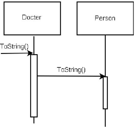
The main difficulty of debugging is the isolation of the fault. One reason of this is the delay between the failure and the causing fault, called the fault delay. Another reason is that the complexity of a program increases when it is executed. An example of this
Figure 4.1: UML model of the Doctor example
increase in complexity is the small program which purpose it is to print the relations between doctors and their patients. The model of this program seen inFigure 4.1is not complex. It consists of two classes representing the doctor and its patient. There is one reference from the doctor to the patient. The implementation of this model can be seen inListing 4.1.
9 return "Patient: " + this._name;
10 }
11 }
12
13 public class Doctor : Person{
14 public Doctor(string name) : base(name){}
15
16 public override string ToString(){
17 string result = "Doctor: "+this._name+"\nPatients:\n";
18 foreach (Person patient in patients){
19 result += patient.ToString() + ’\n’;
20 }
21 return result;
22 }
23
24 private List<Person> patients = new List<Person>();
![Figure 3.1: Context of the .NET Framework (Modified) [Mic03b]](https://thumb-us.123doks.com/thumbv2/123dok_us/1035932.1129028/41.595.180.386.111.318/figure-context-net-framework-modied-mic-b.webp)