CSEIT184523 | Published - 14 April 2018 | March-April-2018 [ (4 ) 5 : 192-201] 192
MEMS
Amit Neelawani
Nagamani Patil, Ramakrishna Pathak, Rashmi Meti, Sudeep Kashetti
Department of Electrical and Electronics Engineering Smt. Kamala and Shri Venkappa, M. Agadi College of Engineeiring and Technology Laxmeshwar, Karnataka, India
I.
INTRODUCTION
WHAT IS SMART DUST?
Autonomous sensing and communication in a cubic millimeter Berkeley‘s Smart Dust project, led by Professors Pister and Kahn, explores the limits on size and power consumption in autonomous sensor nodes. Size reduction is paramount, to make the nodes as inexpensive and easy-to-deploy as possible. The research team is confident that they can incorporate the requisite sensing, communication, and computing hardware, along with a power supply, in a volume no more than a few cubic millimeters, while still achieving impressive performance in terms of sensor functionality and communications capability. These millimeter-scale nodes are called ―Smart Dust.‖ It is certainly within the realm of possibility that future prototypes of Smart Dust could be small enough to remain suspended in air, buoyed by air currents, sensing and communicating for hours or days on end.
'Smart dust' – sensor laden networked computer nodes that are just cubic millimeters in volume. The smart dust project envisions a complete sensor network node, including power supply, processor, and sensor and communications mechanisms, in a single cubic millimeter. Smart dust motes could run for years, given that a cubic millimeter battery can store 1J and could be backed up with a solar cell or vibrational energy source. The goal of the Smart Dust project is to build a millimeter-scale sensing and communication platform for a massively distributed sensor network. This device will be around the size of a grain of sand and will contain sensors, computational ability, bi-directional wireless communications, and a power supply. Smart dust consists of series of circuit and Micro-Electro-Mechanical systems (MEMS) designs to cast those functions into custom silicon. Micro-Electro-Mechanical systems (MEMS) consist of extremely tiny mechanical elements, often integrated together with electronic circuitry.
4
THE MEMS TECHNOLOGY IN SMART DUST
CSEIT184523 | Published - 14 April 2018 | March-April-2018 [ (4 ) 5 : 192-201] 193 advantage of this manufacturing process is not simply that small structures can be achieved but also that thousands or even millions of system elements can be fabricated simultaneously. This allows systems to be both highly complex and extremely low-cost.
Micro-Electro-Mechanical Systems (MEMS) is the integration of mechanical elements, sensors, actuators, and electronics on a common silicon substrate through micro fabrication technology. While the electronics are fabricated using integrated circuit (IC) process sequences (e.g., CMOS, Bipolar processes), the micromechanical components are fabricated using compatible "micromachining" processes that selectively etch away parts of the silicon wafer or add new structural layers to form the mechanical and electromechanical devices. MEMS realize a complete System On chip technology.
Microelectronic integrated circuits can be thought of as the "brains" of a system and allow Microsystems to sense and control the environment. Sensors gather information from the environment through measuring mechanical, thermal, biological, chemical, optical, and magnetic phenomena. The electronics then process the information derived from the sensors and Smart Dust through some decision making capability directs the actuators to respond by moving, positioning, regulating, and filtering, thereby controlling the environment for some desired purpose. Because MEMS devices are manufactured using batch fabrication techniques similar to those used for integrated circuits, unprecedented levels of functionality, reliability, and sophistication can be placed on a small silicon chip at a relatively low cost. The deep insight of MEMS is as a new manufacturing technology, a way of making complex electromechanical systems using batch fabrication techniques similar to those used for integrated circuits, and uniting these electromechanical elements together with electronics. Historically, sensors and actuators are the most costly and unreliable part of a sensor-actuator electronics system. MEMS technology allows these complex electromechanical systems to be manufactured using batch fabrication techniques, increasing the reliability of the sensors and actuators to equal that of integrated circuits. The performance of MEMS devices and systems is expected to be superior to macro scale components and systems, the price is predicted to be much lower.
7
SMART DUST TECHNOLOGY Integrated into a single package are:-
1. MEMS sensors.
2. MEMS beam steering mirror for active optical transmission. 3. MEMS corner cube retro reflector for passive optical transmission. 4. An optical receiver.
5. Signal processing and control circuitry.
CSEIT184523 | Published - 14 April 2018 | March-April-2018 [ (4 ) 5 : 192-201] 194 This remarkable package has the ability to sense and communicate and is self powered. A major challenge is to incorporate all these functions while maintaining very low power consumption. Sensors collect information from the environment such as light, sound, temperature, chemical composition etc.
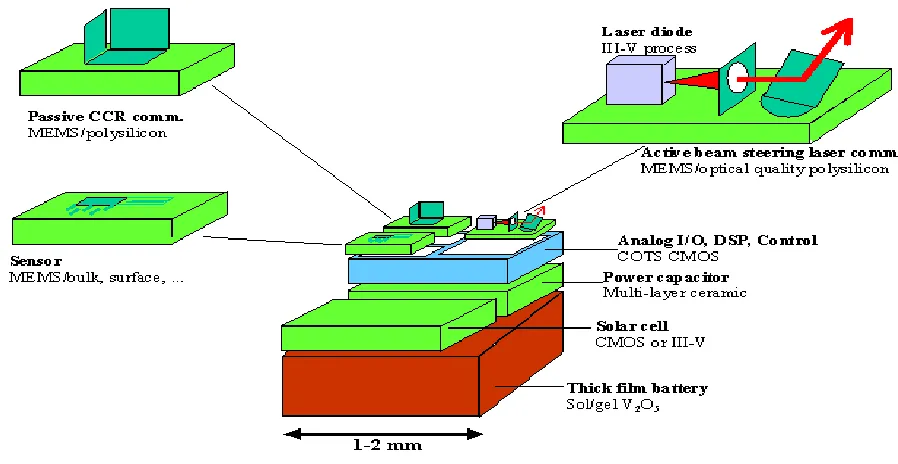
Figure 1. Conceptual diagram of the smart dust mote.
Smart dust employs 2 types of transmission schemes:-
Passive transmission using corner cube retro reflector to transmit to base stations and active transmission using a laser diode & steerable mirrors for mote to mote communication. The photo diode allows optical data reception. Signal processing & control circuitry consists of analog I/O, DSPs to control &process the incoming data. The power system consists of a thick film battery, a solar cell with a charge integrating capacitor for a period of darkness.
OPERATION OF THE MOTE
CSEIT184523 | Published - 14 April 2018 | March-April-2018 [ (4 ) 5 : 192-201] 195 The primary constraint in the design of the Smart Dust motes is volume, which in turn puts a severe constraint on energy since we do not have much room for batteries or large solar cells. Thus, the motes must operate efficiently and conserve energy whenever possible. Most of the time, the majority of the mote is powered off with only a clock and a few timers running. When a timer expires, it powers up a part of the mote to carry out a job, then powers off. A few of the timers control the sensors that measure one of a number of physical or chemical stimuli such as temperature, ambient light, vibration, acceleration, or air pressure. When one of these timers expires, it powers up the corresponding sensor, takes a sample, and converts it to a digital word. If the data is interesting, it may either be stored directly in the SRAM or the microcontroller is powered up to perform more complex operations with it. When this task is complete, everything is again powered down and the timer begins counting again.
9
Another timer controls the receiver. When that timer expires, the receiver powers up and looks for an incoming packet. If it doesn't see one after a certain length of time, it is powered down again. The mote can receive several types of packets, including ones that are new program code that is stored in the program memory. This allows the user to change the behavior of the mote remotely. Packets may also include messages from the base station or other motes. When one of these is received, the microcontroller is powered up and used to interpret the contents of the message. The message may tell the mote to do something in particular, or it may be a message that is just being passed from one mote to another on its way to a particular destination. In response to a message or to another timer expiring, the microcontroller will assemble a packet containing sensor data or a message and transmit it using either the corner cube retro reflector or the laser diode, depending on which it has. The laser diode contains the onboard laser which sends signals to the base station by blinking on and off. The corner cube retro reflector transmits information just by moving a mirror and thus changing the reflection of a laser beam from the base station. This technique is substantially more energy efficient than actually generating some radiation. With the laser diode and a set of beam scanning mirrors, we can transmit data in any direction desired, allowing the mote to communicate with other Smart Dust motes.
10
COMMUNICATING WITH SMART DUST
Smart Dust‘s full potential can only be attained when the sensor nodes communicate with one another or with a central base station. Wireless communication facilitates simultaneous data collection from thousands of sensors. There are several options for communicating to and from a cubic millimeter computer.
radio-CSEIT184523 | Published - 14 April 2018 | March-April-2018 [ (4 ) 5 : 192-201] 196 frequency communication. While the smallest complete radios are still on the order of a few hundred cubic millimeters, there is active work in the industry to produce cubic-millimeter radios.
Moreover RF techniques cannot be used because of the following disadvantages:-
1. Dust motes offer very limited space for antennas, thereby demanding extremely short wavelength (high frequency transmission). Communication in this regime is not currently compatible with low power operation of the smart dust.
2. Furthermore radio transceivers are relatively complex circuits making it difficult to reduce their power consumption to required microwatt levels.
3. They require modulation, band pass filtering and demodulation circuitry.
So an attractive alternative is to employ free space optical transmission. Studies have shown that when a line of sight path is available, well defined free space optical links require significantly lower energy per bit than their RF counterparts.
There are several reasons for power advantage of optical links.
1. Optical transceivers require only simple baseband analog and digital circuitry. 2. No modulators, active band pass filters or demodulators are needed.
3. The short wavelength of visible or near infra red light (of the order of 1 micron) makes it possible for a millimeter scale device to emit a narrow beam (i.e. high antenna gain can be achieved).
OPTICAL COMMUNICATIONS
We have explored two approaches to optical communications: Passive reflective systems and active-steered laser systems.
In a passive communication system, the dust mote does not require an onboard light source. Instead, a special configuration of mirrors can either reflect or not reflect light to a remote source.
Passive reflective systems
CSEIT184523 | Published - 14 April 2018 | March-April-2018 [ (4 ) 5 : 192-201] 197 Applying voltage between this mirror and an electrode beneath it causes the mirror to shift to a position perpendicular to other mirrors, thus causing the light entering the CCR to return to its source—a digital 1. The mirror‘s low mass allows the CCR to switch between these two states up to a thousand times per second, using less than a nanojoule per 0 to 1 transition. A 1 to 0 transition, on the other hand, is practically free because dumping the charge stored on the electrode to the ground requires almost no energy. Our latest Smart Dust device is a 63-mm3 autonomous bidirectional communication mote that receives an optical signal, generates a pseudorandom sequencebased on this signal to emulate sensor data, and then optically transmits the result. The system contains a micro machined corner-cube reflector, a 0.078- mm3 CMOS chip that draws 17 microwatts, and a hearing aid battery. In addition to a battery based operation, we have also powered the device using a 2-mm2 solar cell. This mote demonstrates Smart Dust‘s essential concepts, such as optical data transmission, data processing, energy management, miniaturization and system integration.
A passive communication system suffers several limitations: Unable to communicate with each other, motes rely on a central station equipped with a light source to send and receive data from other motes. If a given mote does have a clear line of sight to the central station, that mote will be isolated from the network. Also, because the CCR reflects only a small fraction of the light emitted from the base station, this system‘s range cannot easily extend beyond 1 kilometer. To circumvent these limitations, dust motes must be active and have their own onboard light source.
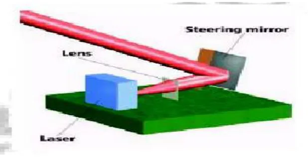
Active-steered laser systems
CSEIT184523 | Published - 14 April 2018 | March-April-2018 [ (4 ) 5 : 192-201] 198 Figure 2. Active steered laser communication system.
Corner cube retro reflector
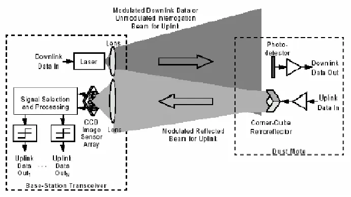
CSEIT184523 | Published - 14 April 2018 | March-April-2018 [ (4 ) 5 : 192-201] 199 Figure 3. Free space optical network utilizing the CCR based passive uplink
The figure illustrates free space optical network utilizing the CCR based passive uplink. The BTS contains a laser whose beam illuminates an area containing dust motes. This beam can be modulated with downlink data including commands to wake up and query the dust motes. When the illuminating beam is not modulated, the dust motes can use their CCRs to transmit uplink data back to the base station. A high frame rate CCD video camera at the BTS sees the CCR signals as lights blinking on and off. It decodes these blinking images to yield the uplink data. Analysis shows that this uplink scheme achieves several kilobits per second over hundreds of meters in full sunlight. At night, in clear, still air, the range should extend to several kilometers. Because the camera uses an imaging process to separate the simultaneous transmissions from dust motes at different locations, we say it uses ‗space division multiplexing‘. The ability for a video camera to resolve these transmissions is the consequence of the short wavelength of visible or near infra red light. This does not require any coordination among the dust motes.
Active optical transmitters
CSEIT184523 | Published - 14 April 2018 | March-April-2018 [ (4 ) 5 : 192-201] 200 MAJOR CHALLENGES
1. To incorporate all these functions while maintaining low power consumption. 2. Maximizing operating life given the limited volume of energy storage.
3. The functionality can be achieved only if the total power consumption is limited to microwatt levels.
4. An unbroken line of sight of path should be available for free space optical links.
APPLICATIONS
1. Civil and military applications where chemical & biological agents in a battle field are detected. 2. Virtual keyboard Glue a dust mote on each of your fingernails. Accelerometers will sense the
orientation and motion of each of your fingertips, and talk to the computer in your watch. Combined with a MEMS augmented-reality heads-up display, your entire computer I/O would be invisible to the people around you.
3. Inventory Control Smart office spaces The Center for the Built Environment has fabulous plans for the office of the future in which environmental conditions are tailored to the desires of every individual. Maybe soon we'll all be wearing temperature, humidity, and environmental comfort sensors sewn into our clothes, continuously talking to our workspaces which will deliver conditions tailored to our needs.
4. Individual dust motes can be attached to the objects one wishes to monitor or a large no: of dust motes may be dispersed in the environment randomly.
5. Dust motes may be used in places where wired sensors are unusable or may lead to errors. E.g.:- Instrumentation of semiconductor processing chambers, wind tunnels, rotating machinery etc. 6. May be used in biological research e.g.:- to monitor movements & internal processes of insects.
HOW FAR THEY HAVE BEEN IMPLEMENTED
1.
The optical receiver for the smart dust project is being developed. The receiver senses incoming laser transmissions at up to 1Mbit/s, for a power consumption of 12NW. Although this is too high for continuous use in smart dust, it is a reasonable figure for the download of small amounts of data such as a 1Kbit program.CSEIT184523 | Published - 14 April 2018 | March-April-2018 [ (4 ) 5 : 192-201] 201 the CCR, it reflects back to the sending position. By modulating the position of one of the mirrors, the reflected beam can be modulated, producing a low-energy passive transmission.
3.
The analog-digital convertor (ADC) the 8bit ADC has so far demonstrated with an input range of1V, equal to the power supply, and a 70kHz sampling rate. The converter draws 1.8NW when sampling at that rate, or 27pJ for an 8bit sample.
4.
The latest smart dust mote, with a volume of just 16cu mm, has been tested. It takes samples from a photo-detector, transmits their values with the CCR and runs off solar cells. So smart dust is on the way.II.
SUMMARY
Smart dust is made up of thousands of sand-grain-sized sensors that can measure ambient light and temperature. The sensors -- each one is called a "mote" -- have wireless communications devices attached to them, and if you put a bunch of them near each other, they'll network themselves automatically.
These sensors, which would cost pennies each if mass-produced, could be plastered all over office buildings and homes. Each room in an office building might have a hundred or even a thousand light- and temperature-sensing motes, all of which would tie into a central computer that regulates energy usage in the building.
Taken together, the motes would constitute a huge sensor network of smart dust, a network that would give engineers insight into how energy is used and how it can be conserved. In a dust-enabled building, computers would turn off lights and climate control in empty rooms. During peak energy usage times, air conditioners that cool servers -- which drain a lot of the tech world's power -- would be automatically shut off, and then turned on again if the servers get too hot. Thus it can very lead to world‘s energy conservation solutions.
III.
REFERENCES
1) hhttttpp::////rroobboottiiccss..eeeeccss..bbeerrkkeelleeyy..eedduu//~~ppiisstteerr//SSmmaarrttDDuusstt/ /
2) hhttttpp::////wwwwww..tthheessttaannddaarrdd..ccoomm//aarrttiiccllee//00,,11990022,,2277557733,,0000..hhttmml l
3) hhttttpp::////wwwwww..wwiirreedd..ccoomm//nneewwss//tteecchhnnoollooggyy//00,,11228822,,4444110011,,0000..hhttmml l
4) hhttttpp::////wwwwww--bbssaacc..eeeeccss..bbeerrkkeelleeyy..eedduu//~~wwaarrnneekkee//SSmmaarrttDDuusstt//
5) hhttttpp::////wwwwww..ccee..bbeerrkkeelleeyy..eedduu//~~ggllaasseerr//CCuurrrreenntt%%2200CCiivviill%%2200AApppplliiccaattiioonnss..ppppt t