CSEIT1846191 | Published – 08 May 2018 | May-June 2018 [ (4 ) 6 : 1004-1010 ]
National conference on Engineering Innovations and Solutions (NCEIS – 2018)
International Journal of Scientific Research in Computer Science, Engineering and Information Technology © 2018 IJSRCSEIT | Volume 4 | Issue 6 | ISSN : 2456-3307
1004
“
Testing Of Basic Electronic Components Using
Avr-Microcontroller
”
Shreesiri M D1, Vidya M R2,Aishwarya K N3, Anitha M4,Divya.S 5
1-4 students of 8th semester, EEE Department, Visvesvaraya technological University, GSSSIETW, Mysuru,
Karnataka, India
5 Assistant Professor, EEE Department, Visvesvaraya technological University, GSSSIETW, Mysuru,
Karnataka, India
ABSTRACT
The testing of basic electronic component was very difficult in preceding days because the testing of each component has to be done in those distinct devices. In this project, all the basic electronic component can be tested in a single kit that can be accomplished using AVR-Microcontroller. In AVR-Microcontroller family, ATMEGA-328 is chosen under 8051 microcontroller, using AVR CODE STUDIO (Version-7.0) Program is given to the ATMEGA-328 Microcontroller, the program will be run and the working condition of basic electronic component can be displayed in LCD(Light emitting display).The LCD will display the condition of basic electronic component by giving the output as “GOOD” or “BAD”.
Keywords: Microcontroller, Resistors, capacitors, inductors, diodes, transistor, voltage regulator, LCD.
I.
INTRODUCTION
In preceding days the basic electronic component were tested using analog multicenter, voltmeter, ammeter, digital multicenter(DMM).But this device cannot be used for integrated circuit because it consists of all most all the basic electronic component which cannot be tested in individual devices. To overcome this drawback in our project we have constructed a component tester were we can test the working condition of all the basic electronic components.
Component testing is a method where testing of each component in an application is done separately. Suppose, in an application there are 5 components. Testing of each 5 components separately and efficiently is called as component testing. Component testing is also known as module and program testing. It finds the defects in the
module and verifies the functioning of software. Component testing is done by the tester Component testing plays a very important role in finding the bugs. Before we start with the integration testing, it is always preferable to do the component testing in order to ensure that each component of an application is working effectively.
The basic electronic components are Resistor, capacitor, inductor diode, BJT, FET, MOSFET, JFET, Thyristor, SCR, DIACs, TRIACs, and IGBT. The above basic electronic components can be tested in a single kit. The component tester is used test the several components. The component tester can test voltage up to 50v.
To construct the components tester here we are
using ATMEGA-328 Microcontroller.
along with memory and programmable input/output peripherals. The ATMEGA-328 is a very popular microcontroller chip produced by ATMEL; it is an 8-bit microcontroller that has 32K of flash memory, 1K of EEPROM and 2K of internal SRAM. Totally, ATMEGA 328 has 28 pins.
The position of component will be detected by TSOP sensor and it is controlled by IR code. The tester does not detect the component it display their working condition, respective values and properties. The tester can be test only electronic component but not power component, because they require more current and power which AVR-Microcontroller could not handle.
The AVR microcontroller is simple, low powered, low cost microcontroller. The most common implementation of this chip is on the popular. Based on this the Arduino Uno and Arduino nano models are prepared. The AVR-Microcontrollers are mainly used in embedded system, so it is also called as embedded microcontroller.
II. LITERATURE REVIEW
1) “Transistor tester with AVR microcontroller and a little more version 1.06k”- Karl Heinz kubbeler , [email protected], Feb 23,2013.
In this paper, we studied that for operation, they have used Atmega 28, Atmega 168 microcontroller & displaying the results to a 2*16-character LCD- display.Automatic detection of NPN & PNP bipolar transistor, N&P channel MOSFET's, JFET's, diodes, double diodes, thyristor & triacs. Automatic detection of pin layout. Measuring of current resolution can be up to 1pf.
2) “The AVR microcontroller & C compiler co-design”- Dr.Gaute myklebust, Atmel Corporation, Atmel development centre, Trondheim, Norway. In this paper, we studied that high-level languages (HLL’s) are rapidly becoming the standard
methodology for embedded microcontrollers
maintenance support. In order to ensure that the new ATMEL AVR family of microcontrollers was well suited as a target for C-compiler, several C compiler development was started before the AVR architecture & instruction set we are completed. During the initial development of the C compiler, several potential improvements in the AVR were identified & implemented. The result of this co-operation between the compiler developer and the AVR development team is a microcontroller for which highly efficient, high performance code is generated. This paper describes the AVR architecture & the changes that were undertaken in the architecture & Instruction set during the compiler development phase in order to make the AVR family of microcontroller’s very suitable targets for a C compiler.
3)”Atmel AVR310: using the USI module as a I2C master”
for this driver. The driver handles transmission according to both standard mode & fast mode.
4) “AVR microcontroller hardware design
considerations” This application note provides basic guidelines to be followed while designing hardware using AVR microcontrollers. Some known problems faced in real-time designs have been addressed by providing possible solutions & work around to resolve them. The scope of this application note is to provide an introduction to potential design problems rather than being an exhaustive documentation on designing applications using AVR microcontrollers. Some of the features of this project are guild lines for providing robust analog & digital power supply,
connection of reset line, interfacing
programmers/debuggers to AVR devices, using external crystals or ceramic resonator oscillators.
III. METHODS AND MATERIAL
The below figure shows the block diagram of component tester.
Figuer 1.1 Block diagram
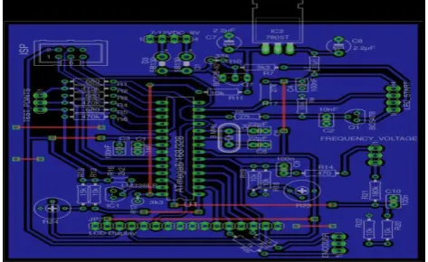
The power supply is having 230V ,50HZ AC supply is given to the component tester kit and rectifier, the rectifier converts from AC to DC because the microcontroller operates in DC voltage that is present in the PCB board .In PCB board it contains resistors, capacitors ,inductors etc,, That means the PCB board consist of integrated circuit which will reduce the voltage from 230V up to 5.5V.This is because ATMEGA328 Microcontroller operates at
5.5V DC .In PCB it contains LCD it shows the display the working condition of the component.
Figuer 1.2 – PCB Board of component tester
The working of component tester is carried out by following procedure. For example if we want to test the working condition of resistor, initially all basic electronic component program will be fed to the ATMEGA328 Microcontroller using AVR code studio (V.0.7).When supply is given to the component tester by placing the resistor on the socket, the microcontroller will select the appropriate program of the component, in that two cases are present, later it will check the cases and it display the working condition of the component that is it GOOD or BAD.
FLOW CHART
The above figure shows flow chart of the AVR CODE STUDIO program. Where this are the steps to be followed while writing the program.
COMPONENT REQUIRED
RESISTOR:
A resistor is a passive two electrical component that implements electrical resistance as a circuit element. In electronic circuits, resistors are used to reduce current flow, adjust signal levels, to divide
voltages, bias active elements, and
terminate transmission lines, among other uses. High-power resistors that can dissipate many watts of electrical power as heat may be used as part of motor controls, in power distribution systems, or as test loads for generators. Fixed resistors have resistances that only change slightly with temperature, time or operating voltage. Variable resistors can be used to adjust circuit elements (such as a volume control or a lamp dimmer), or as sensing devices for heat, light, humidity, force, or chemical activity.
Resistors are common elements of electrical networks and electronic circuits and are ubiquitous in electronic equipment. Practical resistors as discrete components can be composed of various
compounds and forms. Resistors are also
implemented within integrated circuits.
The resistor is a passive electrical component to create resistance in the flow of electric current. In almost all electrical networks and electronic circuits they can be found. The resistance is measured in ohms. An ohm is the resistance that occurs when a current of one ampere passes through a resistor with
a one-volt drop across its terminals. The current is proportional to the voltage across the terminal ends. Ohm’s law represents this ratio:
CAPACITOR:
A capacitor is a passive two-terminal electrical component that stores potential energy in an electric field. The effect of a capacitor is known as capacitance. While some capacitance exists between any two electrical conductors in proximity in a circuit, a capacitor is a component designed to add capacitance to a circuit. The capacitor was originally known as a condenser.
The physical form and construction of practical capacitors vary widely and many capacitor types are in common use. Most capacitors contain at least two electrical conductors often in the form of
metallic plates or surfaces separated by
a dielectric medium. A conductor may be a foil, thin film, sintered bead of metal, or an electrolyte. The non-conducting dielectric acts to increase the capacitor's charge capacity. Materials commonly used as dielectrics include glass, ceramic, plastic film, paper, mica, and oxide layers. Capacitors are widely used as parts of electrical circuits in many common electrical devices. Unlike a resistor, an ideal capacitor does not dissipate energy
INDUCTOR:
stores energy in a magnetic field when electric current flows through it. An inductor typically consists of an insulated wire wound into a coil around a core.
When the current flowing through an inductor changes, the time-varying magnetic field induces an electromotive force (e.m.f.) (voltage) in the conductor, described by Faraday's law of induction. According to Lenz's law, the induced voltage has a polarity (direction) which opposes the change in current that created it. As a result, inductors oppose any changes in current through them.
BJT:
A bipolar junction transistor (bipolar
transistor or BJT) is a type of transistor that uses both electron and hole charge carriers. In contrast, unipolar transistors, such as field-effect transistors, only use one kind of charge carrier. For their operation, BJTs use two junctions between two semiconductor types, n-type and p-type.BJTs are manufactured in two types, NPN and PNP and are available as individual components, or fabricated in integrated circuits, often in large numbers. The basic function of a BJT is to amplify current. This allows BJTs to be used as amplifiers or switches, giving them wide applicability in electronic equipment, including computers, televisions, mobile phones, audio amplifiers, industrial control, and radio transmitters.
PNP NPN
FET:
The field-effect transistor (FET) is a transistor that uses an electric field to control the electrical behaviour of the device. FETs are also known as unipolar transistors since they involve
single-carrier-type operation. Many different
implementations of field effect transistors exist. Field effect transistors generally display very high input
impedance at low frequencies. The conductivity between the drain and source terminals is controlled by an electric field in the device, which is generated by the voltage difference between the body and the gate of the device. The field-effect transistor was first patented by Julius Edgar Lilienfeld in 1926 and
by Oskar Heil in 1934, but
practical semiconducting devices (the junction field-effect transistors [JFETs]) were developed later after the transistor effect was observed and explained by the team of William Shockley at Bell Labs in 1947, immediately after the 20-year patent period eventually expired.
MOSFETs:
MOSET field effect transistor is a unipolar transistor, which acts a voltage-controlled current device and is a device in which current at two electrodes drain and source is controlled by the action of an electric field at another electrode gate having in-between semiconductor and metal very a thin metal oxide layer.
A MOS transistor is called a majority carrier device, in which the current in a conducting channel (the region immediately under the gate) between the source and the drain is modulated bay voltage applied to the gate.
- The majority carriers of an nMOS transistor: Electrons.
- The majority carriers of a pMOS transistor: Holes.
IGBT:
An insulated-gate bipolar transistor (IGBT) is a
three-terminal power semiconductor
alternating layers (P-N-P-N) that are controlled by a metal-oxide-semiconductor (MOS) gate structure without regenerative action. Although the structure of the IGBT is topologically the same as a thyristor with a MOS gate, (MOS gate thyristor), the thyristor action is completely suppressed and only the transistor action is permitted in the entire device operation range. It switches electric power in many
applications: variable-frequency drives
(VFDs), electric cars, trains, variable speed refrigerators, lamp ballasts, air-conditioners and even stereo systems with switching amplifiers.
LIQUID CRYSTAL DISPLAY:
A liquid-crystal display (LCD) is a flat-panel
display or other electronically modulated optical device that uses the light-modulating properties of liquid crystals Liquid crystals do not emit light directly, instead using a backlight or reflector to produce images in color or monochrome.LCDs are available to display arbitrary images (as in a general-purpose computer display) or fixed images with low information content, which can be displayed or hidden, such as preset words, digits, and seven-segment displays, as in a digital clock.
IV. RESULT AND DISCUSSION
Figure 1.4 shows the schematic representation of component Tester built on PCB Board.
Figure 1.5 Arrangement of components on PCB Board
The components used to design the PCB Board is 1x1nF (102) Ceramic Capacitor, 1x10nF (103) Ceramic Capacitor, 4x 100nF (104) Ceramic Capacitor, 2x 22pF (22) Ceramic Capacitor, 2x 2.2uF, 50V Electrolytic Capacitor, 2x 1N5819 or any other Schottky Diode with current rating of 1A, 1x 7805 - 5V Voltage Regulator, 1x LM336 - 2.5V Voltage Reference Diode, 1x 10uH Inductor, 1x BC547 Transistor,1x BC328-40 Transistor, 3x 680 ohm Resistor with 0.1% Tolerance (1% Tolerance would also do), 3x 470k ohm Resistor with 0.1% Tolerance (1% Tolerance would also do), 2x3k3 ohm resistor, 2x 27k ohm resistor, 1x 100k ohm resistor, 1x 33k ohm resistor, 6x 10k ohm resistor, 1x 470 ohm resistor, 1x 15k ohm resistor, 1x 2k2 ohm resistor, 1x 200k ohm resistor, 2x 1k ohm resistor, 2x 10k ohm preset (Variable Resistance), 1x 8MHz Crystal Oscillator, 1x ATMEGA 328/328p with Socket, 1x 16X2 CHARACTER LCD, 1x Rotary Encoder w/ Button Module and KNOB, 1x Red LED (you can use any color I chose Red as it used to denote POWER)
Hardware Parts:-
1x 16 Pin Polarized Header Cable - Relimate Connectors, 3x 3 Pin Polarized Header Cable - Relimate Connectors,2x 4 Pin Polarized Header Cable- Relimate Connectors, 1x 9V Battery Connector, 6x Banana Jack Connectors (Female), 3x Banana Jack Connector Cable (with Male Heads), 1x Enclosure Case (I used a plastic Switch Board Enclosure Case/ Plastic Project Box)
V. CONCLUSION
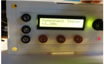
Figure 1.6. output of the component tester
The above figure shows the output of the component tester. If we observe in this figure, the voltage of the component is measured and displayed that is, v1=20mv is shown. The conclusion of this project is, it can check the working condition and also it can measure the voltage and frequency of all the basic electronic component and it is easy to operate.
VI. REFERENCES
[1] Since 1996, NTH has become part of the
Norwegian University of Science and Technology (NTNU)
[2] Jump upalfbogen.com blog
[3] Jump up to:a b "The Story of AVR". youtube.com
[4] Jump up to:a b Myklebust, Gaute. "The AVR
Microcontroller and C Compiler
Co-Design"(PDF). Atmel Norway. CiteSeerX
10.1.1.63.1447 . Retrieved 2012-09-19.
[5] Jump up"UNSW School of Computer Science and
Engineering - General AVR Info".
Cse.unsw.edu.au. Archived from the original on 2012-06-23. Retrieved 2012-09-19.
[6] Jump upAtmel press release. "Atmel's AVR
Microcontroller Ships 500 Million Units".
[7] Jump upField Programmable System Level
Integrated Circuit Archived 2012-11-27 at the Wayback Machine.
[8] Jump upatmel.com
[9] Jump upAtmel Smart Card ICs
[10] 10.Jump up"AVR319: Using the USI module for
SPI communication" (PDF). Atmel. 2004. Retrieved 10 June 2014.
[11] 11.Jump up"Atmel AVR310: Using the USI
Module as a I2C Master" (PDF). Atmel. 2013. Retrieved 10 June 2014.
[12] 12.Jump up"AVR312: Using the USI module as a
I2C slave" (PDF). Atmel. 2005. Retrieved 10 June 2014.
[13] 13.Jump up"AVR307: Half Duplex UART Using
the USI Module" (PDF). Atmel. 2003. Retrieved 10 June 2014.
[14] 14.Jump up"AVR Hardware Design
Considerations" (PDF) (application note). Atmel Corporation. Jun 2015. p. 5. Retrieved 14 Jun 2015. The reset line has an internal pull-up resistor, but if the environment is noisy it can be insufficient and reset can therefore occur sporadically.
[15] 15.Jump up"AVRDUDE programmer".
Savannah.nongnu.org. Retrieved 2012-09-19
[16] 16.Jump up"PDI programming driver" (PDF).
Retrieved 2012-09-19.
[17] 17.Jump up"HVSP_Description".
Support.atmel.no. Archived from the original on 2009-10-12. Retrieved 2012-09-19.
[18] 18.Jump up"DES-encrypted AVR Bootloader"
(PDF). Retrieved 2012-09-19.
[19] 19.Jump up"AES-encrypted AVR Bootloader"
(PDF). Retrieved 2012-09-19.
[20] 20.Jump up"XMEGA Bootloader" (PDF).
Retrieved 2012-09-19.
[21] 21.Jump up"AVR USB Bootloader" (PDF).
Retrieved 2012-09-19.
[22] 22.Jump up"Atmel's Self-Programming Flash
Microcontrollers" (PDF). Retrieved 2012-09-19.[permanent dead link]
[23] 23.Jump up"Guide to understanding JTAG and
security fuses on the AVR". Retrieved 2012-09-19.
[24] 24.Jump up"Atmel-ICE - Atmel Corporation".
Atmel.com. Retrieved 2015-09-11.
[25] 25.Jump up"JTAGICE 3- Atmel Corporation".
Atmel.com. Retrieved 2012-09-19.
[26] 26.Jump up"AVR JTAGICE mkII". Atmel.