1. Quick Setup
3. Programming
2. Features
Aspire Mail
and UltraMail
System Guide
The UltraMail/UltraMail 2000 PCB is for 28i/124i and DS2000 only.• UltraMail uses a compact flash card. • UltraMail 2000 uses a hard disk.
The Aspire Mail/Aspire Mail Plus PCB is for Aspire only. • Aspire Mail uses a compact flash card.
• Aspire Mail Plus uses a hard disk. See the following page for part numbers.
If you are not familiar with the voice mail features, read the Feature Glossary on page 62.
Default Mailbox List
[ ] Indicates Aspire Mail and UltraMail capacities.
Mailbox Type 28i/124i Aspire DS2000
ACD Announcement None
Announcement 800-809
Call Routing 810-814
821-824 831-834 841-844
Directory Dialing None
Distribution 851-860
Future Delivery 861
Guest 819, 820
829, 830 839, 840 849, 850
Interactive None
Message Center 815-818
825-828 835-838 845-848
Modem 862
Network None
Subscriber 301-372 [301-324] 301-499 [301-396] 300-427 [300-331] Trunk 001-052 [001-008] 001-072 [001-024] 101-164 [101-116]
Undefined 713 [105] 666 [17] 745 [89]
Total 1000 [200] 1000 [200] 1000 [200]
Answering Tables=16 Dial Action Tables=100
4. Voice Prompts
This manual has been developed by NEC Unified Solutions, Inc. It is intended for the use of its customers and service personnel, and should be read in its entirety before attempting to install or program the system. Any comments or suggestions for improving this manual would be appreciated. Forward your remarks to:
NEC Unified Solutions, Inc.
4 Forest Parkway Shelton, CT 06484
www.necunifiedsolutions.com
Nothing contained in this manual shall be deemed to be, and this manual does not constitute, a warranty of, or representation with respect to, any of the equipment covered. This manual is subject to change without notice and NEC Unified Solutions, Inc. has no obligation to provide any updates or corrections to this manual. Further, NEC Unified Solutions, Inc. also reserves the right, without prior notice, to make changes in equipment design or components as it deems appropriate. No
representation is made that this manual is complete or accurate in all respects and NEC Unified Solutions, Inc. shall not be liable for any errors or omissions. In no event shall NEC Unified Solutions, Inc. be liable for any incidental or consequential damages in connection with the use of this manual. This document contains proprietary information that is protected by copyright. All rights are reserved. No part of this document may be photocopied or reproduced without prior written consent of NEC Unified Solutions, Inc.
©2004 by NEC Unified Solutions, Inc. All Rights Reserved. Printed in U.S.A.
UltraMail/UltraMail 2000 and Aspire Mail/Aspire Mail Plus Part Numbers
Part Number Description
UltraMail/UltraMail 2000
17712 UltraMail (Flash-based), 2 Port, 3 Hour, 200 Mailboxes, 7000 Messages (max.)
17714 UltraMail (Flash-based), 4 Port, 3 Hour, 200 Mailboxes, 7000 Messages (max.)
17744 UltraMail 2000 (Hard disk), 4 Port, 1400 Hours (approximate) 1000 Mailboxes, 7000 Messages (max.)
Aspire Mail
0891032 Aspire Mail (Flash-based), 2 Port, 3 Hour, 200 Mailboxes, 7000 Messages (max.)
0891037 Aspire Mail (Flash-based), 4 Port, 3 Hour, 200 Mailboxes, 7000 Messages (max.)
0891033 Aspire Mail Plus (Hard disk), 4 Port, 1400 Hours (approximate) 1000 Mailboxes, 7000 Messages (max.)
0891056 Aspire Mail Plus (Hard disk), 8 Port, 1400 Hours (approximate) 1000 Mailboxes, 7000 Messages (max.)
Port Expansion PCBs
Table of Contents
Table of Contents
Chapter 1: Quick Setup . . . 1
Introduction . . . 1
How To Use This Chapter . . . .1
Specifications . . . .2
UltraMail/UltraMail 2000 PCB Installation . . . 3
Installation in 28i/124i and DS2000 . . . .3
28i/124i System Requirements . . . .3
DS2000 System Requirements . . . .3
Installation . . . .4
Shutting Down the UltraMail/UltraMail 2000 PCB . . . 4
Resetting the UltraMail/UltraMail 2000 PCB. . . 4
Adding Ports to the UltraMail/UltraMail 2000 PCB . . . 5
UltraMail/UltraMail 2000 LEDs . . . .6
Connecting UltraMail 2000 to a LAN . . . .7
Connecting UltraMail/UltraMail 2000 to a PC . . . .8
Connecting UltraMail to an External Modem . . . .9
Making Your Own UltraMail/UltraMail 2000 Data Cables . . . .10
Aspire Mail/Aspire Mail Plus PCB Installation . . . 11
Installation in Aspire . . . .11
Aspire System Requirements . . . .11
Installation . . . .11
Shutting Down the Aspire Mail/Aspire Mail Plus PCB . . . 12
Resetting the Aspire Mail/Aspire Mail Plus PCB . . . 12
Adding Ports to the Aspire Mail/Aspire Mail Plus PCB. . . 12
Replacing a 4 Port Aspire Mail/Aspire Mail Plus PCB with an 8 Port Aspire Mail Plus PCB . . . 13
Aspire Mail/Aspire Mail Plus LEDs . . . .15
Connecting Aspire Mail Plus to a LAN . . . .16
Connecting Aspire Mail/Aspire Mail Plus to a PC . . . .17
Programming. . . 18
28i/124i . . . .18
28i/124i Start-Up Programming . . . .18
DS2000 . . . .20
DS2000 Start-Up Programming . . . .20
Aspire. . . .21
Aspire Start-Up Programming . . . .21
Additional Aspire Programming . . . .22
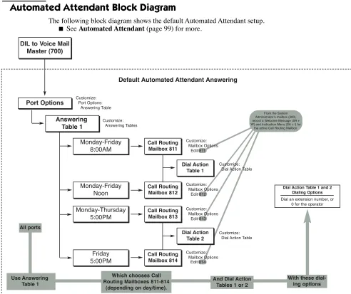
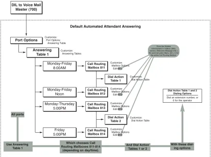
Default Automated Attendant Answering . . . .23
Automated Attendant Block Diagram . . . .23
Admin Installation . . . 24
Installing the Admin Program . . . .24
Admin System Requirements . . . .24
Table of Contents
Setting the Gateway Address for Network Communication . . . .27
Setting the IP Address for Direct (Serial Port) Communication . . . .27
Admin Installation . . . .28
Starting the Admin Program . . . .32
Admin Startup Programming . . . .33
Remote Programming Setup . . . 34
Windows 2000/XP. . . .34
Overview . . . .34
Making a New Dial-Up Connection with Windows 2000 . . . .34
Making a New Dial-Up Connection with Windows XP . . . .36
Calling the Remote System . . . .39
Upgrading the Hardware . . . 43
Installing the 2 Port to 4 Port Software Upgrade. . . .43
Overview . . . .43
Entering a 2-Port Expansion Authorization Code . . . .43
Part 1: Obtaining the 2-Port Expansion Authorization Code . . . 43
Part 2: Entering the 2-Port Expansion Authorization Code . . . 43
Emailing the 2-Port Expansion Authorization Code to Customer Service . . . .44
Upgrading the Software . . . 45
Upgrading Aspire Mail and UltraMail (Flash-Based) Systems. . . .45
Flash-Based Upgrade Procedure . . . .45
Part 1: Backing Up the Site Greetings and Voice Mail Database . . . 45
Part 2: Shutting Down the Voice Mail Application and Removing the Flash Card . . . 46
Part 3: Installing the new Flash Card and Loading the new Aspire Mail or UltraMail Software . . . 46
Part 4: Restoring the Site Greetings and Voice Mail System Database . . . 46
Upgrading Aspire Mail Plus and UltraMail 2000 (Hard Disk-Based) Systems . . . .48
Hard Disk-Based Upgrade Procedure . . . .48
Part 1: Connect to the Aspire Mail Plus or UltraMail 2000 RS232 Port . . . 48
Part 2: Running the Upgrade Utility . . . 48
Part 3: Removing the Flash Card and Restarting . . . 48
Part 4: Verify the IP Address and Gateway Address . . . 48
Enabling the AMIS Networking Option . . . .49
Overview . . . .49
Entering the AMIS Networking Option Authorization Code . . . .49
Part 1: Obtaining the AMIS Networking Option Authorization Code . . . 49
Part 2: Entering the AMIS Networking Option Authorization Code . . . 49
Line Editor . . . 50
Activating the Line Editor . . . .50
Creating Admin Dial-Up Connections . . . 52
Dial-Up Connections for Windows 2000 . . . .52
Creating a Dial-up Network Connection for Windows 2000 . . . .52
Table of Contents
Chapter 2: Features . . . 61
Introduction to Voice Mail Features . . . 61
Feature Glossary . . . 62
ACD Announcement Mailbox . . . 79
Announcement Mailbox. . . 81
Announcement Mailbox Callout . . . 81
Announcement Message . . . 85
Answering Table . . . 86
Answering Machine Emulation . . . 88
Answering Machine Emulation in DS2000. . . 88
Answering Machine Emulation in 28i/124i. . . 88
Answering Machine Emulation in Aspire . . . 88
Answer Schedule Override . . . 90
Auto Attendant Do Not Disturb . . . 92
Auto Erase or Save. . . 94
Auto Forward . . . 95
Auto Help . . . 97
Auto Time Stamp . . . 98
Automated Attendant . . . 99
Automated Attendant Transfer. . . 102
Automatic Routing for Rotary Dial Callers . . . 103
Autosave. . . 104
Bilingual Voice Prompts . . . 105
Broadcast Message. . . 108
Call Announcing . . . 110
Call Blocking . . . 113
Call Forward to a Mailbox . . . 114
Call Queuing . . . 116
Call Routing Mailbox. . . 119
Call Waiting . . . 124
Caller ID. . . 126
Caller ID Automatic Transfer . . . 127
Caller ID with Return Call . . . 128
Calling the Automated Attendant . . . 129
Centralized Voice Mail . . . 130
Centrex Transfer . . . 132
Centrex Transfer with DS2000 . . . 132
Centrex Transfer with 28i/124i . . . 132
Centrex Transfer with Aspire . . . 133
Checking/Deleting a Message . . . 135
Confidential Message. . . 136
Conversation Record . . . 138
Conversation Record in DS2000. . . . 138
Conversation Record in 28i/124i . . . 139
Conversation Record in Aspire . . . 139
Diagnostics. . . 141
Removing Voice Mail Ports from Service. . . 141
Using the Port Self Test Diagnostic. . . 141
Setting Up a Scheduled Daily Archive . . . 142
Table of Contents
Directory Lists . . . 148
Directory Dialing Using a Call Routing Mailbox . . . 149
Directory Dialing Using a Directory Dialing Mailbox . . . 151
Directory Dialing Mailbox. . . 156
Directory Dialing Message . . . 157
Distribution List . . . 158
Distribution Mailbox . . . 160
Erasing All Messages. . . 161
Exiting a Mailbox. . . 162
External Extension . . . 163
Fax Detection . . . 165
First Time Tutorial . . . 166
First Time Tutorial for Guest Mailboxes. . . 166
First Time Tutorial for Subscriber Mailboxes . . . 166
Flexible Answering Schedules. . . 168
Flexible Call Routing . . . 169
Flexible Mailbox Numbering Plan. . . 170
2-Digit Flexible Numbering Plan Example . . . 170
Forced Unscreened Transfer . . . 171
Future Delivery Mailbox . . . 172
Future Delivery Message . . . 173
Description . . . .173
Getting Recorded Help. . . 175
Go To A Mailbox . . . 176
Greeting . . . 178
Remote Greetings . . . 178
Guest Mailbox . . . 181
Hang Up . . . 184
Instruction Menu . . . 185
Disabling Default Messages and Single Digit Dialing . . . 185
Interactive Mailbox . . . 188
Interactive Messaging . . . 189
Interactive Prompts . . . 194
Leaving a Message. . . 195
Leaving a Message for Automated Attendant Callers. . . 195
Listening to Messages . . . 196
Local Backup and Archive. . . 198
Local Backup . . . 198
Archive . . . 198
Local Backup . . . 199
Archive . . . 199
Local Restore and Dearchive . . . 200
Local Restore . . . 200
Dearchive. . . 200
Restore . . . 200
Table of Contents
Make Call . . . 210
Ask Caller’s Number . . . 210
Caller ID Programming . . . 210
Message Notification Programming . . . 211
Ask Caller’s Name Programming . . . 211
DS2000 Programming . . . 212
Message Center Mailbox . . . 214
Message Count Display . . . 217
DS2000 . . . 217
28i/124i . . . 218
Aspire. . . 219
Enhanced Aspire Message Key Operation . . . 220
Message Delete . . . 221
Message Forward . . . 222
Message Length . . . 224
Message Listen Mode . . . 225
Message Notification . . . 226
How Message Notification Works. . . 226
Message Notification to Normal Telephone Numbers . . . 227
Message Notification to Radio Pagers. . . 228
Message Notification to Digital Pagers . . . 229
Message Notification to Message Delivery. . . 231
Cascading Message Notification . . . 232
Message Notification For Guest Mailboxes . . . 234
Message Notification For Message Center Mailboxes . . . 236
Message Notification For Subscriber Mailboxes . . . 238
Message Notification for Urgent Messages . . . 244
Message Playback Direction . . . 245
Message Record . . . 247
Recording Options . . . 247
Message Reply . . . 250
Message Retention . . . 251
Message Status Report . . . 252
Message Storage Limit. . . 253
Message Waiting Lamp . . . 255
Modem Mailbox. . . 256
Monitored Transfer . . . 258
Multiple Company Greetings. . . 260
Music On Hold. . . 261
Network Mailbox . . . 263
Networking (AMIS) . . . 264
Network Alias Mailbox . . . 264
Network Remote Mailbox . . . 264
Network Site Restriction . . . 265
Scheduled Network Delivery. . . 265
Basic Programming at the Sending System. . . 267
Basic Programming at the Receiving System . . . 270
Setting Up Networking Site Restriction . . . 271
Next Call Routing Mailbox . . . 274
Table of Contents
Port Activity . . . 281
Port Self Test . . . 282
Ports In/Out of Service. . . 283
Pre-Greeting Announcement Mailbox . . . 284
Programming Voice Mail. . . 286
Quick Message . . . 287
Real Trace . . . 290
Recording Silence Elimination . . . 291
Remote Diagnostics . . . 292
Remote Programming . . . 293
Reports . . . 294
Return Receipt . . . 296
Screened Transfer. . . 297
Screened vs. Unscreened Transfer. . . 297
Security Code . . . 300
Shutting Down the System. . . 303
Single Digit Dialing . . . 304
Subscriber Mailbox . . . 306
System Administrator . . . 310
System Administrator Mailbox . . . 312
System Re-initialization . . . 313
Tenant Service . . . 314
Time and Date . . . 316
Time and Date Stamp. . . 318
Time and Date Stamp with Caller ID . . . 318
Trace Viewer . . . 319
Transfer Only Mailbox. . . 321
Transfer to a Mailbox. . . 323
Transfer to an ACD/UCD Group . . . 325
Trunk Mailbox . . . 326
Undefined Routing . . . 328
Unscreened Transfer . . . 329
Screened vs. Unscreened Transfer. . . 329
Urgent Message . . . 332
Urgent Message Status . . . 332
Voice Compression Rate . . . 334
Voice Mail Overflow . . . 335
Voice Mail Overflow in 28i/124i and Aspire . . . 335
Voice Mail Overflow in DS2000. . . 335
Voice Prompts . . . 337
Volume Control . . . 338
Welcome Message . . . 339
Table of Contents
Chapter 3: Programming. . . 341
Introduction to Programming . . . 341
Before You Start Programming . . . .341
How To Use This Chapter . . . .341
Admin Main Screen. . . 342
Overview . . . .342
File . . . 343
Install: Phone System (Installation Wizard) . . . .343
Screen 1 – Select The Telephone System . . . 343
Screen 2 – Ports and Mailbox Security Code . . . 343
Screen 3 – Default Language and Voice Compression . . . 344
Screen 4 – Extension and Trunk Numbers . . . 344
Screen 5 – Finish the Installation . . . 345
Install: Ports (Add Voice Mail Ports) . . . .347
Save Database . . . .348
Save Current Report . . . .349
Print . . . .350
Print Preview . . . .351
Print Setup . . . .352
Close . . . .353
View . . . 354
Toolbar. . . .354
Status Bar. . . .355
Trace . . . .356
Trace Viewer . . . .357
Port Activity. . . .358
Message Status. . . .359
Installation Settings . . . .360
Customize . . . 361
Answering Tables . . . .361
[General] Schedule . . . 362
[General] Day(s) or Date. . . 362
[General] Time . . . 363
[General] Mailbox Number . . . 363
Caller I.D. Tables: [General] . . . .365
[General] Match . . . 365
[General] Action . . . 365
Callout Options: [General] . . . .367
[General] General (Non-Pager) Callouts: Wait Between . . . 367
[General] General (Non-Pager) Callouts: Wait Between RNA . . . 367
[General] General (Non-Pager) Callouts: Wait Between Busy. . . 368
[General] General (Non-Pager) Callouts: Wait for Answer (Rings). . . 368
[General] General (Non-Pager) Callouts: Number of Attempts . . . 368
[General] Pager Callouts: Wait Between (Minutes) . . . 368
[General] Pager Callouts: Send Until Acknowledged. . . 368
[General] Callout Report . . . 369
Callout Options: [Optional] . . . .370
Table of Contents
[Optional] Fax Callouts: Number of Attempts . . . 370
[Optional] Fax Callouts: Delay before Fax Carrier Detect (Seconds) . . . 370
[Optional] Hotel/Motel: Snooze Alarm Timer (Minutes) . . . 371
[Optional] Hotel/Motel: Number of Rings per Wake-Up Call . . . 371
[Optional] Caller ID: Insert Leading “1” . . . 371
[Optional] Caller ID: Make Call Suffix Digits . . . 371
Dial Action Tables: [General] . . . .373
[General] Key . . . 375
[General] DIRF Action – Directory Dial by First Name . . . 375
[General] DIRL Action – Directory Dial by Last Name. . . 375
[General] GOTO Action – Go to Mailbox . . . 376
[General] HUP Action – Hang Up . . . 376
[General] LANG1 Action – Switch to Language 1. . . 376
[General] LANG2 Action – Switch to Language 2. . . 376
[General] LOGON Action – Log Onto Voice Mail . . . 376
[General] MTRF Action – Monitored (Ring No Answer) Transfer . . . 377
[General] REC1 Action – Quick Message with Greeting . . . 377
[General] REC1C Action – Quick Confidential Message with Greeting . . . . 377
[General] REC1U Action – Quick Urgent Message with Greeting . . . 378
[General] REC2 Action – Quick Message without Greeting . . . 378
[General] REC2C Action – Quick Confidential Message without Greeting . 378 [General] REC2U Action – Quick Urgent Message without Greeting . . . 378
[General] TRF Action – Screened Transfer . . . 379
[General] UND Action – Undefined Routing (No Routing). . . 379
[General] UTRF Action – Unscreened Transfer . . . 379
[General] Number . . . 381
Distribution Lists: [General] . . . .383
[General] Index . . . 383
[General] Mailbox Number . . . 383
Mailbox Options: Add . . . .385
Mailbox . . . 385
Mailbox Type . . . 385
Mailbox Options: Edit . . . .387
Start Number . . . 387
End Number . . . 387
Mailbox Types. . . 387
Select All Button . . . 387
Unselect All Button . . . 387
OK Button . . . 387
Cancel Button . . . 387
Mailbox Options: Delete . . . .388
Mailbox . . . 388
Mailbox Type . . . 388
OK Button . . . 388
Cancel Button . . . 388
Table of Contents
Mailbox Options: Announcement: [General] . . . .391
[General] Options: Mailbox Type . . . 391
[General] Options: Security Code . . . 391
[General] Options: Name . . . 391
[General] Options: Department . . . 392
[General] Options: Next Call Routing Mailbox . . . 392
[General] Options: Tenant. . . 392
[General] Options: Directory List . . . 392
[General] Announcement: Repeat Count . . . 393
[General] Announcement: Hang Up After . . . 393
Mailbox Options: Announcement: [Callouts] . . . .394
[Callouts] Options: Enable Callouts . . . 394
[Callouts] Options: Phone Number . . . 394
[Callouts] Options: Call Type . . . 395
[Callouts] Options: Callout Begin Time . . . 395
[Callouts] Options: Callout End Time . . . 395
[Callouts] Options: Wait Between Callouts . . . 395
[Callouts] Options: Day(s) for Callout . . . 395
Mailbox Options: Call Routing: [General] . . . .397
[General] Options: Mailbox Type . . . 398
[General] Options: Name . . . 398
[General] Options: Department . . . 398
[General] Options: Tenant. . . 399
[General] Options: Directory List . . . 399
Mailbox Options: Call Routing: [Call Handling] . . . .400
[Call Handling] Options: Dial Action Table . . . 400
[Call Handling] Options: Delay Rings Before Redirect Transfer . . . 400
[Call Handling] Options: Directory List To Use. . . 401
[Call Handling] Options: Time Limit for Dialing Commands . . . 401
[Call Handling] Options: Play Default Messages . . . 401
Mailbox Options: Directory Dialing: [General] . . . .402
[General] Options: Mailbox Type . . . 402
[General] Options: Name . . . 402
[General] Options: Department . . . 403
[General] Options: Tenant. . . 403
[General] Options: Directory List . . . 403
Mailbox Options: Directory Dialing: [Call Handling] . . . .404
[Call Handling] Options: Dial Action Table . . . 404
[Call Handling] Options: Delay rings Before Redirect Transfer . . . 404
[Call Handling] Options: Directory List to Use . . . 404
[Call Handling] Options: Time Limit for Dialing Commands . . . 405
Mailbox Options: Distribution: [Normal] . . . .406
[General] Options: Mailbox Type . . . 406
[General] Options: Name . . . 406
[General] Options: Department . . . 407
[General] Options: Distribution List . . . 407
[General] Options: Tenant. . . 407
[General] Options: Directory List . . . 407
Mailbox Options: Future Delivery: [General] . . . .408
Table of Contents
[General] Options: Department . . . 409
[General] Options: Directory List . . . 409
[General] Options: Number of Messages . . . 409
Mailbox Options: Guest: [General] . . . .410
[General] Options: Mailbox Type . . . 410
[General] Options: Security Code . . . 410
[General] Options: Name . . . 410
[General] Options: Department . . . 411
[General] Options: Extension . . . 411
[General] Options: Next Call Routing Mailbox . . . 412
[General] Options: Tenant. . . 412
[General] Options: Directory List . . . 413
[General] Options: Number of Messages . . . 413
[General] Options: Bilingual Mode. . . 413
Mailbox Options: Guest: [Message Notification] . . . .414
[Message Notification] Options: Message Notification/Fax Callbacks . . . 414
[Message Notification] Options: Local Callouts . . . 414
[Message Notification] Options: Long Distance Calls . . . 415
[Message Notification] Options: Area Codes: Index . . . 415
[Message Notification] Options: Area Codes: Area Code Entry . . . 415
[Message Notification] Message Notification Numbers: Index . . . 415
[Message Notification] Message Notification Numbers: Notification Number . . . 416
[Message Notification] Message Notification Numbers: Call Type . . . 417
[Message Notification] Message Notification Numbers: Notification Mode . 417 [Message Notification] Message Notification Numbers: Security Code Required . . . 418
Mailbox Options: Guest: [Messaging]. . . .419
[Messaging] Options: Message Playback . . . 419
[Messaging] Options: Message Listen Mode . . . 419
[Messaging] Options: Auto Forwarding . . . 420
[Messaging] Options: Auto Erase/Save of Messages . . . 420
[Messaging] Options: Message Retention. . . 420
[Messaging] Options: Urgent Message Return Time . . . 420
[Messaging] Options: Recording Conversation Beep . . . 421
[Messaging] Options: Ask Caller’s Number . . . 421
[Messaging] Options: Record Reply Only . . . 421
Mailbox Options: Guest: [Lamp/Logon/Transfer] . . . .422
[Lamp/Logon/Transfer] Lamp: Message Waiting Lamp . . . 422
[Lamp/Logon/Transfer] Lamp: Access Digit/Lamp String On. . . 422
[Lamp/Logon/Transfer] Lamp: Access Digit/Lamp String Off . . . 423
[Lamp/Logon/Transfer] Transfer: Forced Unscreened Transfer. . . 424
[Lamp/Logon/Transfer] Transfer-Only Mailbox . . . 425
[Lamp/Logon/Transfer] Logon: Use Remote Logon as Direct Logon . . . 425
[Lamp/Logon/Transfer] Logon: First Log In Option . . . 425
Table of Contents
[General] Options: Next Call Routing Mailbox . . . 429
[General] Options: Tenant. . . 429
[General] Options: Directory List . . . 430
Mailbox Options: Interactive: [Interactive] . . . .431
[Interactive] Options: Silence Limit for Responses . . . 431
[Interactive] Options: Mailbox for Responses . . . 431
[Interactive] Options: Record Incomplete Responses . . . 432
[Interactive] Options: Time Limit for Dialing Commands . . . 432
[Interactive] Options: Reference Number for Call . . . 432
Mailbox Options: Message Center: [General]. . . .433
[General] Options: Mailbox Type . . . 433
[General] Options: Security Code . . . 433
[General] Options: Name . . . 434
[General] Options: Department . . . 434
[General] Options: Extension . . . 434
[General] Options: Next Call Routing Mailbox . . . 435
[General] Options: Next Call Routing Mailbox Dial Mode . . . 436
[General] Options: Tenant. . . 438
[General] Options: Directory List . . . 438
[General] Options: Number of Messages . . . 438
[General] Options: Bilingual Mode. . . 439
Mailbox Options: Message Center: [Message Notification] . . . .440
[Message Notification] Options: Message Notification/Fax Callbacks . . . 440
[Message Notification] Options: Local Callouts . . . 440
[Message Notification] Options: Long Distance Calls . . . 441
[Message Notification] Options: Area Codes: Index . . . 441
[Message Notification] Options: Area Codes: Area Code Entry . . . 441
[Message Notification] Message Notification Numbers: Index . . . 441
[Message Notification] Message Notification Numbers: Notification Number . . . 442
[Message Notification] Message Notification Numbers: Call Type . . . 443
[Message Notification] Message Notification Numbers: Notification Mode . 443 [Message Notification] Message Notification Numbers: Security Code Required . . . 444
Mailbox Options: Message Center: [Messaging] . . . .445
[Messaging] Options: Message Playback . . . 445
[Messaging] Options: Message Listen Mode . . . 445
[Messaging] Options: Auto Forwarding . . . 446
[Messaging] Options: Auto Erase/Save of Messages . . . 446
[Messaging] Options: Message Retention. . . 446
[Messaging] Options: Urgent Message Return Time . . . 446
[Messaging] Options: Recording Conversation Beep . . . 447
[Messaging] Options: Ask Caller’s Number . . . 447
Mailbox Options: Message Center: [Lamp/Logon/Transfer] . . . .448
[Lamp/Logon/Transfer] Lamp: Message Waiting Lamp . . . 448
[Lamp/Logon/Transfer] Lamp: Access Digit/Lamp String On. . . 448
[Lamp/Logon/Transfer] Lamp: Access Digit/Lamp String Off . . . 449
[Lamp/Logon/Transfer] Transfer: Forced Unscreened Transfer. . . 450
[Lamp/Logon/Transfer] Transfer-Only Mailbox . . . 451
Table of Contents
Mailbox Options: Modem: [General] . . . .453
[General] Options: Mailbox Type . . . 453
[General] Options: Security Code . . . 453
[General] Options: Name . . . 454
[General] Options: Department . . . 454
[General] Options: Next Call Routing Mailbox . . . 454
[General] Options: Tenant. . . 454
[General] Options: Directory List . . . 454
Mailbox Options: Network: [General]. . . .456
[General] Options: Mailbox Type . . . 456
[General] Options: Security Code . . . 456
[General] Options: Name . . . 457
[General] Options: Department . . . 457
[General] Options: Next Call Routing Mailbox . . . 457
[General] Options: Next Call Routing Mailbox Dial Mode . . . 458
[General] Options: Tenant. . . 461
[General] Options: Directory List . . . 461
[General] Options: Number of Messages . . . 462
[General] Options: Bilingual Mode. . . 462
Mailbox Options: Network: [Network] . . . .463
[Network] Options: Mailbox Type . . . 463
[Network] Options: Mailbox . . . 463
[Network] Options: Call Type. . . 464
[Network] Options: Networking Site Restriction Options . . . 465
[Network] Options: Prefix Number. . . 466
[Network] Options: Country Code . . . 466
[Network] Options: Area Code . . . 466
[Network] Options: Phone Number . . . 466
[Network] Delivery: Begin Time (hour) . . . 467
[Network] Delivery: End Time (hour) . . . 467
[Network] Delivery: Wait Between (minutes) . . . 467
[Network] Miscellaneous: Auto Forwarding . . . 467
[Network] Miscellaneous: Message Retention . . . 468
[Network] Miscellaneous: Alternate Next CRMB Dial Option . . . 468
Mailbox Options: Subscriber: [General] . . . .469
[General] Options: Mailbox Type . . . 469
[General] Options: Security Code . . . 469
[General] Options: Name . . . 470
[General] Options: Department . . . 470
[General] Options: Extension . . . 470
[General] Options: Next Call Routing Mailbox . . . 470
[General] Options: Next Call Routing Mailbox Dial Mode . . . 471
[General] Options: Tenant. . . 474
[General] Options: Directory List . . . 474
[General] Options: Number of Messages . . . 475
Table of Contents
[Message Notification] Message Notification Numbers: Index . . . 477
[Message Notification] Message Notification Numbers: Notification Number . . . 478
[Message Notification] Options: Call Type . . . 479
[Message Notification] Options: Notification Mode. . . 479
[Message Notification] Options: Security Code Required . . . 480
Mailbox Options: Subscriber: [Messaging]. . . .481
[Messaging] Options: Message Playback . . . 481
[Messaging] Options: Message Listen Mode . . . 481
[Messaging] Options: Auto Forwarding . . . 482
[Messaging] Options: Auto Erase/Save of Messages . . . 482
[Messaging] Options: Message Retention. . . 482
[Messaging] Options: Urgent Message Return Time . . . 482
[Messaging] Options: Recording Conversation Beep . . . 483
[Messaging] Options: Ask Caller’s Number . . . 483
Mailbox Options: Subscriber: [Lamp/Logon/Transfer]. . . .484
[Lamp/Logon/Transfer] Lamp: Message Waiting Lamp . . . 484
[Lamp/Logon/Transfer] Lamp: Access Digit/Lamp String On. . . 484
[Lamp/Logon/Transfer] Lamp: Access Digit/Lamp String Off . . . 485
[Lamp/Logon/Transfer] Transfer: Forced Unscreened Transfer. . . 486
[Lamp/Logon/Transfer] Transfer-Only Mailbox . . . 486
[Lamp/Logon/Transfer] Logon: Use Remote Logon as Direct Logon . . . 487
[Lamp/Logon/Transfer] Logon: First Log In Option . . . 487
[Lamp/Logon/Transfer] Logon: First Log In Announcement Mailbox . . . 487
[Lamp/Logon/Transfer] External Extension: Enabled . . . 487
[Lamp/Logon/Transfer] External Extension: Number . . . 488
Mailbox Options: Subscriber: [Subscriber] . . . .489
[Subscriber] Options: Park/Paging String . . . 489
[Subscriber] Options: Call Waiting String . . . 490
[Subscriber] Options: Call Announcing . . . 490
[Subscriber] Options: System Administrator . . . 491
[Subscriber] Options: Call Queuing . . . 491
[Subscriber] Options: Block Auto Attendant . . . 492
[Subscriber] Options: Pre-Greeting Announcement Mailbox. . . 492
Mailbox Options: Trunk: [General]. . . .493
[General] Options: Mailbox Type . . . 493
[General] Options: Name . . . 493
[General] Options: Department . . . 493
[General] Options: Extension . . . 494
[General] Options: Tenant. . . 494
[General] Options: Directory List . . . 494
[General] Options: Bilingual Mode. . . 494
[General] Answering Schedule Table . . . 495
Outbound Notification: Add List. . . .496
Outbound Notification: Edit List . . . .497
Outbound Notification: Delete List . . . .498
Port Options: [General] . . . .499
[General] Options: Tenant. . . 499
[General] Options: Extension . . . 499
Table of Contents
[General] Options: Callouts: Allow Lamp . . . 500
[General] Options: Callouts: Allow Notification/Wake-Up . . . 501
[General] Options: Callouts: Allow Network . . . 501
[General] Options: Do Immediate Self Test . . . 501
[General] Options: Clear Port’s Failure . . . 501
System Options: [General 1] . . . .502
[General 1]: Options: Mailbox Default Security Code . . . 502
[General 1]: Options: Incoming Network Call Mode . . . 503
[General 1]: Options: Default Bilingual Mode . . . 504
[General 1]: Tenant: Intertenant Messaging . . . 504
[General 1]: Tenant: Number of Tenants . . . 504
[General 1]: Eliminate Recording Silence: Enabled . . . 505
[General 1]: Eliminate Recording Silence: Delay before (msec) . . . 505
System Options: [General 2] . . . .506
[General 2]: Mailbox Logon: Time Limit (seconds). . . 506
[General 2]: Mailbox Logon: Attempt Limit . . . 506
[General 2]: Dialing Commands: Time Limit (seconds) . . . 506
[General 2]: Dialing Commands: Attempt Limit . . . 507
[General 2]: Directory Dialing: Minimum Entry . . . 507
[General 2]: Directory Dialing: Play Extension Number . . . 507
[General2]: System Password: Password . . . 507
[General 2]: Call Queuing: Hold Timer (seconds) . . . 508
[General 2]: Call Queuing: Number of Idle Ports . . . 508
[General 2]: Miscellaneous: Port Self Test Timer (minutes) . . . 508
[General 2]: Miscellaneous: Greeting for Quick Message / Mailbox Transfer . . . 508
[General 2]: Miscellaneous: Auto Disk Maintenance Time . . . 508
[General 2]: Miscellaneous: Day for Auto Disk Defrag. . . . 509
[General 2]: Miscellaneous: TCPIP Service Number . . . 509
System Options: [Dial Strings] . . . .510
[Dial Strings]: Hold Retrieval Strings: RNA: . . . 510
[Dial Strings]: Hold Retrieval Strings: Busy: . . . 511
[Dial Strings]: Transfer Strings: Internal: . . . 511
[Dial Strings]: Transfer Strings: External: . . . 511
[Dial Strings]: Miscellaneous Strings: Hang Up. . . 512
[Dial Strings]: Miscellaneous Strings: Call Pickup. . . 512
[Dial Strings]: Miscellaneous Strings: Ringdown. . . 512
[Dial Strings]: Miscellaneous Strings: Off Hook Call Announce. . . 513
[Dial Strings]: External Hold Retrieval Strings: RNA . . . 514
[Dial Strings]: External Hold Retrieval Strings: Busy . . . 514
[Dial Strings]: Lamp Strings: On . . . 515
[Dial Strings]: Lamp Strings: Off . . . 515
System Options: [Timer] . . . .517
[Timer]: Message Length (seconds): Subscriber. . . 517
[Timer]: Message Length (seconds): Nonsubscriber . . . 517
Table of Contents
[Timer]: Timers (1 = 10 msec): Hang Up Timer. . . 519
[Timer] System Time/Date: Time . . . 519
[Timer] System Time/Date: Date . . . 519
Tenant Options: [General] . . . .520
[General] Strings: Site ID String . . . 520
[General] Strings: Site’s Network Telephone Number . . . 521
[General] Strings: Fax Detect Dial String . . . 522
[General] Strings: Digital Pager Callback Number. . . 522
[General] Timers: Delay in Dialing Pager Callback Number . . . 523
[General] Timers: Delay Before Pager Announcement . . . 523
[General] Remote Tenant: Enabled. . . 523
[General] Remote Tenant: Access Digits . . . 523
Tenant Options: [Access Digits] . . . .525
[Access Digits] Access Digits Before Local Callout . . . 525
[Access Digits] Access Digits Before Long Distance Callout . . . 526
[Access Digits] Access Digits Before Network Local Callout . . . 526
[Access Digits] Access Digits Before Network Long Distance Callout . . . 527
Reports. . . 529
Multiple Reports . . . .529
Auto Attendant: Port . . . .530
Auto Attendant: Trunk. . . .531
Answering Schedules. . . .532
Caller ID Table . . . .533
Callout: Options. . . .534
Callout: Log . . . .535
Dial Action Table . . . .536
Distribution Lists . . . .537
Fax: Documents . . . .538
Fax: Distribution . . . .539
Fax: Fax Ports . . . .540
Mailbox: Options . . . .541
Mailbox: Directory List . . . .543
Mailbox: Numeric List . . . .544
Mailbox: Access Count . . . .545
Mailbox: Call Flags . . . .547
Message Usage . . . .548
Port: Options . . . .549
Port: Usage. . . .550
System Options . . . .551
Activity . . . .552
Tools. . . 553
Backup . . . .553
Restore . . . .555
Archive . . . .556
Dearchive. . . .557
Ports In/Out of Service . . . .558
Immediate All Ports Self Test . . . .559
Immediate Clear All Ports Failure. . . .560
Serial Communication Ports . . . .561
Table of Contents
Options. . . .564
[Options]: Field Validation Warning: Error Beep. . . 564
[Options]: Field Validation Warning: Error Message Box . . . 564
Days to keep trace messages: . . . 564
Reset Trace Database . . . 565
Autosave . . . 565
Cancel Warning. . . 565
Auto Correct Invalid Field . . . 565
Event Codes Filter for Trace Database . . . 566
Info Text Color . . . 566
Toolbar . . . 567
Save Report . . . .567
Print Report . . . .568
Port Activity. . . .569
Real Trace . . . .571
Trace Viewer . . . .572
Trace Viewer: Select Query Dialog Box . . . .573
Database Name . . . 573
Restore Backup Database . . . 573
Port Number . . . 573
Mailbox Number . . . 573
Event Code Window . . . 573
Select All Event Codes . . . 574
Unselect All Event Codes . . . 574
Date / Time / Trace String. . . 574
Trace Viewer: Trace Viewer Report . . . .574
Message Status. . . .577
About . . . .579
Chapter 4: Voice Prompts. . . 581
Voice Prompts . . . 581
Chapter 5: Soft Keys . . . 617
Soft Keys . . . 617
28i/124i Soft Keys . . . .617
Keyset Soft Keys . . . .617
Keyset Status Line. . . 617
Keyset Soft Key Chart. . . 618
Super Display Status Line . . . 623
Super Display Soft Key Chart . . . 624
Aspire Soft Keys . . . .630
Introduction
1
Chapter 1:
Quick Setup
Introduction
Introduction
How To Use This Chapter
Use this chapter to:
■ Install the UltraMail/UltraMail 2000 and Aspire Mail/Aspire Mail Plus PCBs in their respective
tele-phone systems. UltraMail/UltraMail 2000 is compatible with 28i/124i and DS2000. Aspire Mail/Aspire Mail Plus is compatible only with Aspire.
■ Program the telephone systems to work with the UltraMail/UltraMail 2000 and Aspire Mail/Aspire Mail
Plus PCBs.
■ Install the Admin Program. This is a Windows-based administrative program that provides access to all
Introduction
Specifications
The following table shows the basic capacities of the UltraMail/UltraMail 2000 systems.
The following table shows the basic capacities of the Aspire Mail/Aspire Mail Plus systems. Capacities
UltraMail (Flash-based) UltraMail 2000 (Hard disk)
Ports 2, 4, 6, 8 4, 8
Mailboxes 200 1000
Storage Hours 3 1400 (Approximate)
Maximum Messages 7000 7000
Capacities
Aspire Mail (Flash-based) Aspire Mail Plus (Hard disk)
Ports 2, 4, 6, 8 4 Port PCB: 4, 8
8 Port PCB: 8, 16
Mailboxes 200 1000
Storage Hours 3 1400 (Approximate)
UltraMail/UltraMail 2000 PCB Installation
Installation in 28i/124i and DS2000
1
UltraMail/UltraMail 2000 PCB Installation
Installation in 28i/124i and DS2000
28i/124i System Requirements
Installation in 28i/124i requires the following:
■ 28i/124i/124i EXCPRU System Software version 6.01.01 or higher.
■ Review the following i-Series Port Requirements table. It shows the number of station ports (and corre-sponding extensions) required for each UltraMail/UltraMail 2000 configuration.
DS2000 System Requirements
Installation in DS2000 requires the following: ■ System Software version 3.**.** or higher. ■ CPU PCB P/N 80025B.
■ UltraMail/UltraMail 2000 uses the DS2000 predefined voice mail ports. It does not use station ports. i-Series Port Requirements
Part Number Description Station Ports Extensions
17712 2 Port UltraMail (Flash-based) 4 21
17714 4 Port UltraMail (Flash-based) 4 4
17712 with 0891045 2 Port UltraMail (Flash-based) with 4 Port Expansion
8 61
17714 with 0891045 4 Port UltraMail (Flash-based) with 4 Port Expansion
8 8
17744 4 Port UltraMail 2000 (Hard disk) 4 4
17744 with 0891034 4 Port UltraMail 2000 (Hard disk) with 4 Port Expansion
8 8
UltraMail/UltraMail 2000 PCB Installation
Installation in 28i/124i and DS2000
Installation
Before installing the UltraMail/UltraMail 2000 PCB, be sure the phone system is powered up and function-ing normally.
■ UltraMail/UltraMail 2000 without the Expansion PCB installed uses 4 extension numbers. ■ UltraMail/UltraMail 2000 with the Expansion PCB installed uses 8 extension numbers. Before installing the UltraMail/UltraMail 2000 PCB:
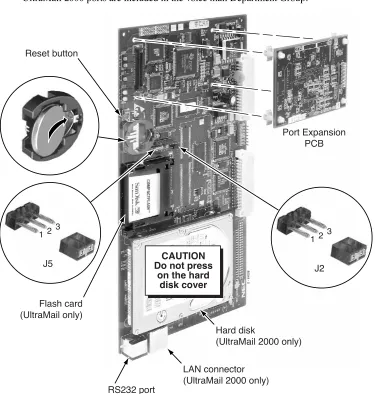
1. Insert the battery into the battery clips. It provides battery back-up for the PCBs Real Time Clock. 2. Check the position of jumper J2.
- For UltraMail (i.e., without a hard disk), place the J2 jumper on pins 1 and 2. - For UltraMail 2000 (i.e., hard disk version), place the J2 jumper on pins 2 and 3. 3. Check the position of jumper J5.
- If connecting directly to a PC serial port, place the J5 jumper on pins 1 and 2. - If connecting to an external modem, place the J5 jumper on pins 2 and 3. To install the UltraMail/UltraMail 2000 PCB:
1. Plug in the UltraMail/UltraMail 2000 PCB as follows: - In 28i, use slots 3-5 only.
- In 124i, use slots 4, 6. or 8 only.
(Slot 8 is recommended. Slot 4 disables slot 5; slot 6 disables slot 7.) - In DS2000, use slots CN2-CN8 only.
2. Allow about 1 minute for the UltraMail/UltraMail 2000 PCB and voice mail application software to load.
3. Check the LEDs for proper operation. See Figure 2: UltraMail/UltraMail 2000 LEDs on page 6. 4. Go to 28i/124i Start-Up Programming on page 18 and DS2000 Start-Up Programming on page 20 for
more.
Shutting Down the UltraMail/UltraMail 2000 PCB
You should always shut down the UltraMail/UltraMail 2000 PCB before unplugging it or powering down the telephone system. Shutting down the UltraMail/UltraMail 2000 PCB will also shut down the associated voice mail application program.
To shut down the UltraMail/UltraMail 2000 PCB: 1. Momentarily press the red Reset switch.
2. Verify that the Shut Down LED is On (either green or red). See Figure 2: UltraMail/UltraMail 2000 LEDs on page 6 for more.
Resetting the UltraMail/UltraMail 2000 PCB
You may need to reset the UltraMail/UltraMail 2000 PCB for maintenance purposes. Resetting the PCB will Important
UltraMail/UltraMail 2000 PCB Installation
Installation in 28i/124i and DS2000
1
Adding Ports to the UltraMail/UltraMail 2000 PCB
The Port Expansion PCB expands your UltraMail/UltraMail 2000 PCB from 4 ports to 8 ports. To install the Port Expansion PCB:
1. Shut down the UltraMail/UltraMail 2000 PCB.
2. Unplug the UltraMail/UltraMail 2000 PCB and place it on a flat, clean, static-free surface. 3. Snap in the plastic standoffs as shown below, then plug in the Port Expansion PCB.
4. Plug the UltraMail/UltraMail 2000 PCB back into the same slot from which you removed it. 5. The UltraMail/UltraMail 2000 PCB and voice mail application program will automatically restart. 6. In 28i/124i, use the following programs to set up the additional ports added by the expansion PCB.
■ 1003 - Extension (Department) Groups
■ 1001 - Basic Extension Port Setup (Part A), Item 5: Terminal Type
7. If your Admin Program is already installed, go to View: Installation Settings on page 360to verify that the additional ports are properly installed.
■ In 28i/124i, turn to 28i/124i Start-Up Programming on page 18 (Step 2) and verify that all UltraMail/ UltraMail 2000 ports are included in the voice mail Department Group.
80044 - 5
Reset button
Flash card (UltraMail only)
Port Expansion PCB
RS232 port
LAN connector (UltraMail 2000 only)
Hard disk
(UltraMail 2000 only)
CAUTION Do not press
on the hard disk cover
J2
1 2 3
J5
UltraMail/UltraMail 2000 PCB Installation
Installation in 28i/124i and DS2000
UltraMail/UltraMail 2000 LEDs
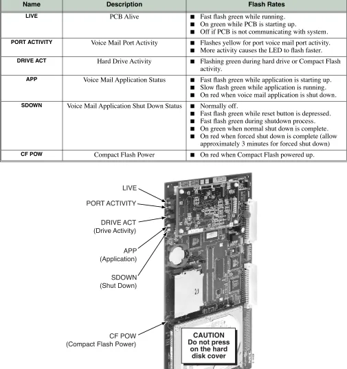
The LEDs show the status of the UltraMail/UltraMail 2000 PCB. Refer to the table below for LED flash rates. UltraMail/UltraMail 2000 PCB LEDs
Name Description Flash Rates
LIVE PCB Alive ■ Fast flash green while running.
■ On green while PCB is starting up.
■ Off if PCB is not communicating with system.
PORT ACTIVITY Voice Mail Port Activity ■ Flashes yellow for port voice mail port activity.
■ More activity causes the LED to flash faster.
DRIVE ACT Hard Drive Activity ■ Flashing green during hard drive or Compact Flash
activity.
APP Voice Mail Application Status ■ Fast flash green while application is starting up.
■ Slow flash green while application is running. ■ On red when voice mail application is shut down.
SDOWN Voice Mail Application Shut Down Status ■ Normally off.
■ Fast flash green while reset button is depressed. ■ Fast flash green during shutdown process. ■ On green when normal shut down is complete. ■ On red when forced shut down is complete (allow
approximately 3 minutes for forced shut down)
CF POW Compact Flash Power ■ On red when Compact Flash powered up.
LIVE
APP (Application) DRIVE ACT (Drive Activity) PORT ACTIVITY
UltraMail/UltraMail 2000 PCB Installation
Installation in 28i/124i and DS2000
1
Connecting UltraMail 2000 to a LAN
You can use the UltraMail 2000 LAN (Local Area Network) connection for local and remote programming. The Admin program can use this connection for programming the voice mail application on the PCB.
To connect UltraMail 2000 to a LAN:
1. Be sure the UltraMail 2000 PCB is properly plugged in and running. 2. Following the manufacturer’s instructions, install your hub, router, or switch.
3. Using standard CAT5 straight-through cables, connect the UltraMail 2000 and your PC to LAN connec-tions on your hub, router, or switch.
■ (Optional) To directly connect to the LAN connector, use a CAT5 cross-over cable. 4. Verify that the green LED on the UltraMail 2000 PCB LAN connector is flashing.
■ If this LED is off, your LAN connection is not functioning.
5. Optionally connect your hub, router, or switch to your WAN (Wide Area Network).
CAUTION Do not press
on the hard disk cover
80044 - 8
LAN connector (UltraMail 2000 Only)
Straight-through CAT5 cables
Power supply
UltraMail/UltraMail 2000 PCB Installation
Installation in 28i/124i and DS2000
Connecting UltraMail/UltraMail 2000 to a PC
You can directly connect your PC to the UltraMail/UltraMail 2000 RS232 port for local programming. The Admin program can use this connection for programming the voice mail application on the PCB.
To connect UltraMail/UltraMail 2000 to your PC:
1. Be sure the UltraMail/UltraMail 2000 PCB is properly plugged in and running. 2. Verify that the J5 jumper is on pins 1 and 2.
3. Plug the DIN end of the 8-Pin DIN to Mod-8 Cable (P/N 80893) into the UltraMail/UltraMail 2000 RS232 port.
■ See Making Your Own UltraMail/UltraMail 2000 Data Cables on page 10 if you choose to make your
own cables.
4. Plug one end of the DB9 to Mod-8 Adaptor (P/N 85980) into the cable. 5. Plug the other end of the adaptor into the RS232 port on the back of your PC.
■ Your PC may require adaptors or a different cable configuration.
CAUTION Do not press
on the hard disk cover
80044 - 7
RS232 port
UltraMail/UltraMail 2000 PCB Installation
Installation in 28i/124i and DS2000
1
Connecting UltraMail to an External Modem
You can connect the UltraMail PCB to an external modem for remote programming. The Admin program can use this connection for remotely programming the voice mail application on the PCB.
To connect UltraMail to an External Modem:
1. Be sure the UltraMail PCB is properly plugged in and running. 2. Verify that the J5 jumper is on pins 2 and 3.
3. Plug the DIN end of the 8-Pin DIN to Mod-8 Cable (P/N 80893) into the UltraMail RS232 port.
■ See Making Your Own UltraMail/UltraMail 2000 Data Cables on page 10 if you choose to make your
own cables.
4. Plug one end of the DB25 to Mod-8 Adaptor (P/N 85981) into the cable.
5. Plug the other end of the adaptor into the DB25F connector on the back of your modem. ■ Your modem may require adaptors or a different cable configuration.
6. Following the instructions that came with your modem, connect a trunk and the modem’s power supply.
Compatibility Guidelines:
■ This setup is only applicable to UltraMail (flash-based). UltraMail 2000 (hard disk) has an internal modem and uses its Modem Mailbox for remote programming.
CAUTION Do not press
on the hard disk cover
80044 - 6
RS232 port
P/N 80893
P/N 85981 To
trunk
UltraMail/UltraMail 2000 PCB Installation
Installation in 28i/124i and DS2000
Making Your Own UltraMail/UltraMail 2000 Data Cables
Use the drawing below if you choose to make your own UltraMail/UltraMail 2000 data cables. It is highly rec-ommended that you purchase cable P/N 80893 and adaptor P/Ns 85980 and 85981 instead of making your own cables.
Aspire Mail/Aspire Mail Plus PCB Installation
Installation in Aspire
1
Aspire Mail/Aspire Mail Plus PCB Installation
Installation in Aspire
Aspire System Requirements
Installation in Aspire requires the following: ■ System Software version 0.26 or higher.
■ Review the following Aspire Port Requirements table. It shows the number of station ports (and corre-sponding extensions) required for each Aspire Mail/Aspire Mail Plus configuration.
Installation
Before installing the Aspire Mail/Aspire Mail Plus PCB, be sure the phone system is powered up and func-tioning normally. In addition, make a record of your system’s extension numbers. Once installed, Aspire Mail/Aspire Mail Plus will use the next consecutive set of 4, 8, or 16 extension numbers (depending on the capacity of the PCB).
■ Aspire Mail PCBs (P/Ns 0891032 and 0891037) and the 4 Port Aspire Mail Plus PCB (P/N 0891033)
without the Expansion PCB use 4 extension numbers. These PCBs with the Expansion PCB installed use
8 extension numbers.
■ The 8 Port Aspire Mail Plus PCB (P/N 0891056) without an Expansion PCB uses 8 extension numbers. This PCB with the Expansion PCB installed uses 16 extension numbers.
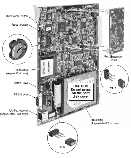
Before installing the Aspire Mail/Aspire Mail Plus PCB: 1. Slide the RUN/BLOCK switch (if installed) to the RUN position.
2. Insert the battery into the battery clips. It provides battery back-up for the PCB’s Real Time Clock. 3. Check the position of jumper TP8.
- For Aspire Mail (i.e., without a hard disk), place the TP8 jumper on pins 1 and 2. - For Aspire Mail Plus (i.e., hard disk version), place the TP8 jumper on pins 2 and 3.
Aspire Port Requirements
Part Number Description Station Ports Extensions
0891032 2 Port Aspire Mail (Flash-based) 4 21
0891037 4 Port Aspire Mail (Flash-based) 4 4
0891032 with 0891045 2 Port Aspire Mail (Flash-based) with 4 Port Expansion
8 61
0891037 with 0891045 4 Port Aspire Mail (Flash-based) with 4 Port Expansion
8 8
0891033 4 Port Aspire Mail Plus (Hard disk) 4 4
0891033 with 0891034 4 Port Aspire Mail Plus (Hard disk) with 4 Port Expansion
8 8
0891056 8 Port Aspire Mail Plus (Hard disk) 8 8
0891056 and 0891057 8 Port Aspire Mail Plus (Hard disk) with 8 Port Expansion
16 16
1 The two excess ports cannot be used by any other device.
Important
Aspire Mail/Aspire Mail Plus PCB Installation
Installation in Aspire
5. Check the position of the SW3 switches.
- All four SW3 switches must be in the Off position (i.e., pushed away from the PCB). To install the Aspire Mail/Aspire Mail Plus PCB:
1. Plug Aspire Mail/Aspire Mail Plus into any available universal slot (S1-S8). 2. Allow about 1 minute for the PCB and voice mail application software to load.
3. Check the Aspire LEDs for proper operation. See Figure 8: Aspire Mail/Aspire Mail Plus LEDs on page 15 for more.
4. Go to Aspire Start-Up Programming on page 21 to set up your Aspire Mail/Aspire Mail Plus programming. Shutting Down the Aspire Mail/Aspire Mail Plus PCB
You should always shut down the Aspire Mail/Aspire Mail Plus PCB before unplugging it or powering down the Aspire system. Shutting down the PCB will also shut down the associated voice mail application program. To shut down the Aspire Mail/Aspire Mail Plus PCB:
1. Momentarily press the Reset switch.
2. Verify that the Shut Down LED is On (green or red). See Figure 8: Aspire Mail/Aspire Mail Plus LEDs on page 15 for more.
Resetting the Aspire Mail/Aspire Mail Plus PCB
You may need to reset the PCB for maintenance purposes. Resetting the PCB will also restart the associated voice mail application program.
■ If you reset the Aspire system using the Reset switch on the CPRU PCB, you must reset the Aspire Mail/Aspire Mail Plus PCB after the phone system restarts.
To reset the Aspire Mail/Aspire Mail Plus PCB: 1. Press the Reset switch for about 5 seconds.
■ (Wait for the LIVE, APP and SDOWN LEDs to come on green.) 2. The PCB and voice mail application program will restart.
Adding Ports to the Aspire Mail/Aspire Mail Plus PCB
The Port Expansion PCBs add additional voice mail ports to your Aspire Mail/Aspire Mail Plus PCB. Expansion PCB P/N 0891045 adds 4 additional ports to Aspire Mail PCB P/Ns 0891032 and 0891037. Expansion PCB P/N 0891034 adds 4 additional ports to Aspire Mail Plus PCB P/N 0891033. Expansion PCB P/N 0891057 adds 8 additional ports to Aspire Mail Plus PCB P/N 0891056.
To install the Port Expansion PCB:
1. Shut down the Aspire Mail/Aspire Mail Plus PCB.
2. Unplug the Aspire Mail/Aspire Mail Plus PCB and place it on a flat, clean, static-free surface.
3. Snap in the plastic standoffs as in shown Figure 7: Aspire Mail/Aspire Mail Plus PCB on page 14, then Important!
Aspire Mail/Aspire Mail Plus PCB Installation
Installation in Aspire
1
7. Use the following programs to set up the additional voice mail ports added by the expansion PCB.
■ 16-02-01: Department Group Assignment for Extensions
■ 15-03-01: Single Line Telephone Basic Data Setup - SLT Signaling Type
■ 15-03-03: Single Line Telephone Basic Data Setup - Terminal Type
■ 15-03-09: Single Line Telephone Basic Data Setup, Caller ID Function for External Module
8. If you are adding ports to the 8 Port Aspire Mail Plus PCB (P/N 0891056), go to File:Install: Ports (Add
Voice Mail Ports) on page 347 to add the additional 8 ports on the Expansion PCB.
9. Go to View: Installation Settings on page 360to verify that the additional ports are properly installed. Replacing a 4 Port Aspire Mail/Aspire Mail Plus PCB with an 8 Port Aspire Mail Plus PCB
Review the following instructions if you want to upgrade your telephone system by replacing a 4 port PCB (P/N 0891032, 0891033, or 0891037) with an 8 Port Aspire Mail Plus PCB (P/N 0891056).
To replace a 4 Port PCB with an 8 Port Aspire Mail Plus PCB: 1. Shut down the 4 port PCB.
2. Unplug the existing 4 port PCB.
3. Use 90-05: Slot Control to delete the slot from which you removed the 4 port PCB.
4. Plug the new 8 Port Aspire Mail Plus PCB into the same slot from which you removed the old PCB. 5. The new Aspire Mail Plus PCB and voice mail application program will automatically restart. 6. Use the following programs to set up the additional voice mail ports added by the new PCB.
■ 16-02-01: Department Group Assignment for Extensions
■ 15-03-01: Single Line Telephone Basic Data Setup - SLT Signaling Type
■ 15-03-03: Single Line Telephone Basic Data Setup - Terminal Type
■ 15-03-09: Single Line Telephone Basic Data Setup, Caller ID Function for External Module
Aspire Mail/Aspire Mail Plus PCB Installation
Installation in Aspire
0893100 - 129
Reset button Run/Block Switch
Port Expansion PCB
Switch SW3 Flash card (Aspire Mail only)
RS232 port
LAN connector (Aspire Mail Plus only)
Hard disk
(Aspire Mail Plus only)
CAUTION Do not press
on the hard disk cover
TP8
1 2 3
1 2 3
Aspire Mail/Aspire Mail Plus PCB Installation
Installation in Aspire
1
Aspire Mail/Aspire Mail Plus LEDs
The LEDs show the status of the Aspire Mail/Aspire Mail Plus PCB. Refer to the table below for LED flash rates. Aspire Mail/Aspire Mail Plus PCB LEDs
Name Description Flash Rates
LIVE PCB Alive ■ Fast flash green while running.
■ On green while PCB is starting up.
■ Off if PCB is not communicating with system.
APP Voice Mail Application Status ■ Fast flash green while application is starting up.
■ Slow flash green while application is running. ■ On red when voice mail application is shut down.
SDOWN Voice Mail Application Shut Down Status ■ Normally off.
■ Fast flash green while reset button is depressed. ■ Slow flash green during shutdown process. ■ On green when normal shut down is complete. ■ On red when forced shut down is complete (allow
approximately 3 minutes for forced shut down)
BL1-BL8 Voice Mail Port Activity ■ On red when port is active.
CF POW Compact Flash Power ■ On red when Compact Flash is powered up. DRIVE ACT Hard Drive Activity ■ Flashing green during hard drive or Compact Flash
activity.
HDD POW Hard Drive Power ■ On red when hard drive is powered up.
LIVE APP (Application)
CF POW
(Compact Flash Power) DRIVE ACT
(Drive Activity) HDD POW (Hard Drive Power) SDOWN
(Shut Down)
Aspire Mail/Aspire Mail Plus PCB Installation
Installation in Aspire
Connecting Aspire Mail Plus to a LAN
You can use the Aspire Mail Plus LAN (Local Area Network) connection for local and remote programming. The Admin program can use this connection for programming the voice mail application on the PCB.
To connect Aspire Mail Plus to a LAN:
1. Be sure the Aspire Mail Plus PCB is properly plugged in and running. 2. Following the manufacturer’s instructions, install your hub, router, or switch.
3. Using standard CAT5 straight-through cables, connect the Aspire Mail Plus and your PC to LAN con-nections on your hub, router, or switch.
■ (Optional) To directly connect to the LAN connector, use a CAT5 cross-over cable.
4. Verify that the green LED on the Aspire Mail/Aspire Mail Plus PCB LAN connector is flashing. ■ If this LED is off, your LAN connection is not functioning.
5. Optionally connect your hub, router, or switch to your WAN (Wide Area Network).
0893100 - 133
LAN connector (Aspire Mail Plus Only)
Typical hub, router, or switch
CAUTION Do not press
Aspire Mail/Aspire Mail Plus PCB Installation
Installation in Aspire
1
Connecting Aspire Mail/Aspire Mail Plus to a PC
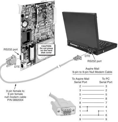
You can directly connect your PC to the Aspire Mail/Aspire Mail Plus RS232 port for local programming. The Admin program can use this connection for programming the voice mail application on the PCB. To connect Aspire Mail/Aspire Mail Plus to your PC:
1. Be sure the Aspire Mail/Aspire Mail Plus PCB is properly plugged in and running. 2. Verify that the TP16 jumper is on pins 1 and 2.
3. Plug one end of a 9-pin female to 9-pin female null modem cable into the RS232 port on the Aspire Mail/ Aspire Mail Plus PCB.
4. Plug the other end of the same cable into the RS232 port on the back of your PC. ■ Your PC may require adaptors or a different cable configuration.
0893100 - 131
RS232 port
RS232 port
9 pin female to 9 pin female null modem cable
P/N 0892004
CAUTION Do not press
on the hard disk cover
DTE
DTE
Aspire Mail
9-pin to 9-pin Null Modem Cable To Aspire Mail
Serial Port To PC Serial Port 2 3 5 7 8 6 1 4 9 3 2 5 8 7 4 1 6 9 5 4 3 2 1
9 8 7 6 5 4 3 2 1
Programming
28i/124i
Programming
28i/124i
28i/124i Start-Up Programming
Windows PC Program references are in square [ - ] brackets. Step 1 Run the Automatic Extension Setup program.
1.1 0004 - Automatic Extension Circuit Type Setup.
[Program Fields: Hardware Setup: O/M: Terminal Auto-Set]
- This program will automatically identify the UltraMail/UltraMail 2000 PCB.
1.2 Reset the UltraMail/UltraMail 2000 PCB.
Step 2 Assign the UltraMail/UltraMail 2000 station ports to a unique Department Group.
2.1 1003 - Extension (Department) Groups
[Program Fields: Extensions: General Extension Setup: Department Group]
- Assign the UltraMail/UltraMail 2000 station ports to a unique Department Group (e.g., 2). - In 28i and 124i, UltraMail/UltraMail 2000 ports are permanently assigned to ports 61-68. - No other station ports should be in this group.
- Be sure to set up the Department Groups in order. (In 28i, for example, port 61 should be order 1, port 62 should be order 2, etc.)
✔
By default, the UltraMail/UltraMail 2000 station ports are not assigned (0). Step 3 Assign a master number to the UltraMail/UltraMail 2000 Department Group.3.1 0516 - Voice Mail Master Number
[Program Fields: System Options: Other: Department Groups]
- Assign the master number for the UltraMail/UltraMail 2000 Department Group (e.g., 700).
✔
By default, the master number is 600.Step 4 Specify the UltraMail/UltraMail 2000 Department Group as the voice mail group.
4.1 0410 - Extension (Department Group Options), Item 3: Voice Mail Group
[Program Fields: System Options: Other: Department Groups]
- For the Department Group you assigned in step 2 above (e.g., 2), enter 1 to assign the Department Group as a voice mail group.
✔
By default, this option is 0 (i.e., not a voice mail group). Step 5 Set the terminal type for all UltraMail/UltraMail 2000 station ports.5.1 1001 - Basic Extension Port Setup (Part A), Item 5: Terminal Type
[Program Fields: Extensions: Physical Extension Setup: Station Ports]
- Enter 1 for each UltraMail/UltraMail 2000 station port.
✔
By default, this option is 0.Step 6 Program Voice Mail keys on system extensions.
6.1 1006 - Programming Function Keys
[Program Fields: Extensions: Physical Extension Setup: Options: Function Keys]
- Voice Mail keys are code 1059.
- Normally, the additional data is the number of the extension you are programming. - Keysets can also have Voice Mail keys for Virtual Extensions, a co-worker, or an
unin-stalled extension (for Message Center operation).
Programming
28i/124i
1
Step 7 To have the UltraMail/UltraMail 2000 Automated Attendant answer outside calls, set up DILs to voice mail.
7.1 0901 - Basic Trunk Port Setup (Part A), Items 14-17: Trunk Service Type
[Program Fields: Trunks: Options]
- Assign Service Type 4 to each trunk you want to be a DIL.
✔
By default, trunks are Service Type 0 (Normal).7.2 0917: DIL Assignment
[Program Fields: Trunks: Options]
- For each trunk you designated in step 7.1, enter the first (lowest) UltraMail/UltraMail 2000 station port as the DIL destination (e.g., 61). These are the ports you assigned to the Ultra-Mail/UltraMail 2000 Department Group in step 2 above.
Programming
DS2000
DS2000
DS2000 Start-Up Programming
Step 1 Set up the Automated Attendant to answer outside calls during the day and at night.
1.1 1003 - Trunk Options: Direct Termination (Day)
- Enter the UltraMail/UltraMail 2000 master number (700) for each trunk that you want UltraMail/UltraMail 2000 to answer during the day and at night.
✔
By default, all trunks are set to Key Ring (entered by pressing CLEAR). Step 2 Optionally set up the Automated Attendant to answer outside calls only at night.2.1 1003 - Trunk Options: Direct Termination (Night)
- Enter the UltraMail/UltraMail 2000 master number (700) for each trunk that you want UltraMail/UltraMail 2000 to answer only at night.
✔
By default, all trunks are set to Key Ring (entered by pressing CLEAR). No other startup programming is required.■ DS2000 system software automatically installs the UltraMail/UltraMail 2000 PCB and detects the proper number of voice mail ports.
■ The UltraMail/UltraMail 2000 master extension number is 700. ■ Voice mail ports are 500-507.