THIS MANUAL The Installation Service Manual provides the information required to install, program, and maintain the Electra Professional Level II and Level II Advanced systems.
This manual is divided into three chapters as follows: Chapter 1: Hardware Specifications and Installation
Chapter 1 provides the information required to prepare and install the systems, including applicable FCC requirements and UL regulatory information.
Chapter 2: Programming
Chapter 2 provides detailed instructions for performing System Programming. Chapter 3: Guide to Feature Programming
Chapter 3 provides a guide or “roadmap” of the Memory Blocks associated with a feature that are either required or can be programmed.
Chapter 4: System Maintenance
Chapter 4 provides maintenance instructions and flowcharts for the systems.
SUPPORTING
DOCUMENTS In addition to the Installation Service Manual, the Electra Professional Level II and Level II Advanced systems are supported by the following technical manuals:
Electra Professional Level II and Level II Advanced General Description Manual (Stock Number 722020)
Designed and developed to provide a general overview of the Electra Professional Level II and Level II Advanced systems, its features, configuration, service features, specifications, and standards.
Electra Professional Level II and Level II Advanced Features and Specifications Manual (Stock Number 722021)
Provides an expanded discussion of each feature that is available for the Electra Professional Level II and Level II Advanced systems. In addition, the Features and Specifications Manual provides Station Application, Operating Procedures, and Service Renditions.
Electra Professional Level II and Level II Advanced Station Operations Manual (Stock Number 722023)
Electra Professional Level II and Level II Advanced Job Specifications Manual (Stock Number 722024)
Used in conjunction with the Installation Service Manual, the Job Specifications Manual is designed for the service technicians who are responsible for planning the system installation, maintaining the system, and keeping records of system programming and configuration. [This manual is included with the CPU-F( l-20 KTU.]
Electra Professional Level II and Level II Advanced Automatic Call Distribution Manual (Stock Number 720234)
This manual is also included with the MIF-F(A)-10 KTU ( Stock Number 720233). It is designed to provide the service technician with the instructions for programming the ACD feature. This manual is also intended for the ACD supervisor, at the customer’s site, to use to become familiar with the system in order to take full advantage of the ACD/MIS feature.
Electra Professional Level II and Level II Advanced Least Cost Routing Manual This manual is included with the Least Cost Routing software (Stock No. 722302). It provides instructions for the service technician for programming the customer’s site for Least Cost Routing.
Electra Professional Level II and Level II Advanced Svstem Program Technician Manual
This manual is included with the System Program Technician Software (Stock No. 722305). It is intended for use by the service technician when using the PC software to program the Electra Professional Level II and Level II Advanced systems. This manual _ explains the use of the various screens within the PC software that allow the technician to program the system to meet the individual customer’s needs.
Electra Professional Level II and Level II Advanced Ssstem Program End-User Manual
CHAPTER 1
HARDWARE SPECIFICATIONS
Electra Professional Level II & Level II Advanced
CHAPTER 1
HARDWARE SPECIFICATIONS AND INSTALLATION TABLE OF CONTENTS
December 1993
SECTION 1 INTRODUCTION
1.1 1.2
1.3 1.4 1.5
General Information . . .
... l-l
... l-l RegulatoryInformation . . . l-2 1.2.1 Company Notification ... l-3 1.2.2 BatteryDisposal ... l-4 1.2.3 IncidenceofHarm ... l-5 1.2.4 Radio Frequency Interference ... l-5 1.2.5 Hearing Aid Compatibility ... l-5 1.2.6 DirectInwardDiaIing ... l-5 1.2.7 Voice Announcement/Monitoring Over DID Lines ... l-6 1.2.8 Music On Hold ... l-6 1.2.9 ServiceRequirements ... l-6 1.2.10 UL Regulatory Information ... l-6 1.2.11 DOCRequirements ... l-7 EquipmentList ... l-8 Equipment General Information ... l-10 EquipmentDescription ... l-10 1.5.1 Level II Key Service Units and Power Supply Units ... l-10 1.5.2 Level II Advanced Key Service Units and Power Supply Units ... l-l 1 1.5.3 CommonControl Key Telephone Unit ... l-11 1.5.4 Station Interface Key Telephone Units ... 1-12 1.5.5 Trunk Interface Key Telephone Units ... 1-12 1.5.6 Optional Key Telephone Units ... l-14 1.5.7 Multiline Terminals and Associated Equipment ... 1-15 1.5.8 Single Line Telephone Adaptor ... 1-16
?_
SECTION 2 SYSTEM SPECIFICATIONS . . . 1:16 2.1 GeneralInformation ... 1-16 2.2 SystemBlockDiagram ... 1-17 2.3 System Control Capacities ... 1-19 2.4 Cabling Requirements ... l-20
2.4.1 Cabling Specifications ... l-20 2.4.2 Cabling Precautions ... 1-21
December 1993 Electra Professional Level II & Level II Advanced Installation Service Manual 2.5 2.6 2.7 2.8 2.9 2.10 2.11 2.12 2.13
Power Requirements ... l-2 1 2.5.1 Power Supply Inputs ... l-21 2.5.2 Power Supply Outputs Table ... l-22 2.53 Power Consumption and Dissipation Table ... l-22 2.5.4 Fuse Replacement Table ... l-22 Environmental Conditions ... l-23 OutsideLineTypes ... 1-23
Network and Control Specifications ... l-23 2.8.1 Transmission ... l-23
2.8.2 Network ... l-23 2.8.3 Control ... 1-23
2.8.4 Telephones ... l-24 DialingSpecifications ... 1-24
2.9.1 Dial Pulse Address Signaling ... 1-24 2.9.2 DTMF Address Signaling ... l-24 BatteryBackup ... l-25
2.10.1 System Backup ... l-25 2.10.2 Memory Backup ... 1-25 Weights and Dimensions ... l-26 ExternalEquipmentInterface ... l-27 -
2.12.1 2.12.2 2.12.3 2.12.4 2.12.5 2.12.6
Music On Hold/Station Background Music ... 1-27 External Paging (Audio) ... l-27 External Tone Ringer/Night Chime Output ... 1-27 SMDROutput ... l-27
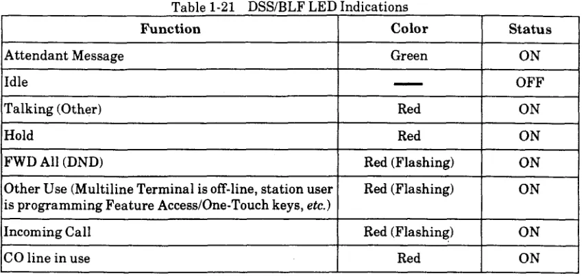
PCConnection ... l-27 RelayContact ... l-27 Visual and Audible Indications . . . 1-28 2.13.1 Tone Patterns Table . . . 1-28 2.13.2 Multiline Terminal LED Flash Pattern Table . . . 1-29 2.13.3 DSS/BLF LED Indications Table . . . l-30
SECTION 3 HARDWARE REQUIREMENTS . . . l-30 3.1 GeneralInformation ... l-30
3.1.1 Programming Stations ... l-30 3.1.2 Attendant Station ... l-30 3.2 Determining Required Equipment ... 1-3 1
3.2.1 Station Equipment ... 1-31 3.2.2 InterfaceKTUs ... 1-31 3.3 InstallationExample ... 1-35
SECTION 4 KSU INSTALLATION . . . 1-36 4.1
4.2
4.3
4.4
GeneralInformation ... 1-36 Site Preparation and MDF/IDF Construction ... l-36 4.2.1 Precautionary Information ... l-36 4.2.2 SiteSurvey ... l-36 4.2.3 Site Limitations ... l-36 4.2.4 Site Selection Conditions ... l-37 4.2.5 MDF Construction ... l-37 Installing the Level II Key Service Unit (KSU) ... 1-38 4.3.1 Basic KSU (ESF-SB-10 KSU) ... 1-38 4.3.2 Expansion KSU (ESF-SE-10 KSU) ... l-39 4.3.3 Opening the KSU Cover ... l-40 4.3.4 Wall Mounting the Basic and/or Expansion KSUs ... l-40 4.3.4.1 Wall Mounting the Basic KSU ... l-40 4.3.4.2 Wall Mounting the Expansion KSU ... 1-42 4.3.5 Floor Mounting the Basic and/or Expansion KSUs ... l-45
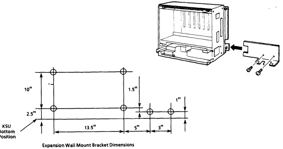
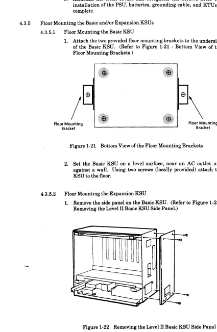
4.3.5.1 Floor Mounting the Basic KSU ... 1-45 4.3.5.2 Floor Mounting the Expansion KSU ... 1-45 4.3.6 Adding the Expansion KSU to an Installed System ... 1-48 4.3.7 Installing a PSF-S-20 PSU in the Basic and Expansion KSUs ... l-50
4.3.7.1 General Information ... l-50 4.3.7.2 Installing a PSF-S-20 PSU in the Basic KSU ... l-51 4.3.7.3 Installing a PSF-S-20 PSU in the Expansion KSU ... l-51 4.3.8 Battery Installation ... l-53 4.3.8.1 Connecting the Built-In Batteries ... l-53 4.3.8.2 Installing and Connecting Expansion Batteries ... 1-54 4.3.8.3 CableRouting ... l-55 4.3.9 Grounding Requirements ... l-56 Installing the Level II Advanced Key Service Unit (KSU) ... l-57 4.4.1 BasicKSU (ESF-XB-10 KSU) ... l-57 4.4.2 Expansion KSU (ESF-XE-10 KSU) ... l-57 4.4.3 Opening the KSU Cover ... l-58 4.4.4 Wall Mounting the Basic and/or Expansion KSUs ... 1-59
4.4.4.1 Wall Mounting the Basic KSU ... l-59 4.4.4.2 Wall Mounting the Expansion KSU ... l-60 4.4.5 Floor Mounting the Basic and/or Expansion KSUs ... 1-62
4.4.5.1 Floor Mounting the Basic KSU ... l-62 4.4.5.2 Floor Mounting the Expansion KSU ... l-63
Chapter 1 - Table of Contents . . .
December 1993 Electra Professional Level II & Level II Advanced Installation Service Manual
4.4.6 Installing a PSF-P-PO PSU in the Basic and Expansion KSUs ... l-64 4.4.6.1 GeneralInformation ... l-64
4.4.6.2 Installing a PSF-P-20 PSU in the Basic KSU ... 1-65 4.4.6.3 Installing a PSF-P-20 PSU in the Expansion KSU ... 1-66 4.4.7 Battery Installation ... l-67
4.4.7.1 Connecting the Built-In Batteries ... 1-67 4.4.7.2 Installing and Connecting Level II Advanced Expansion Batteries ... 1-69 4.4.8 Grounding Requirements ... l-70
SECTION 5 INSTALLING A KEY TELEPHONE UNIT (KTU) ... l-71
5.1
5.2
5.3
5.4
General Information ... 51.1 Installation Precautions ... 5.1.2 KTU Installation ... Common Control KTUs ... 5.2.1 CPU-F( I-20 KTU ... 52.2 MMC-F-11 KTU ... Interface KTUs ...
. . . . . . . . . . ... ... . . 1-71
. . 9 . . . . . . . ... ... . . 1-71
* . . . . . . . . . ... ... . . 1-71
. . . . . . . . . ... ... l-72
. . . . . . . . . . * 1-72
. . . . . * . . . . , . . l-76
53.1 5.3.2 5.3.3 5.3.4 5.3.5 5.3.6 5.3.7 5.3.8
. . . . . . . . . . . ...*... . . 1-78
ESI-F(8)-21 KTU . . . 1-78 SLI-F(8G)-21 KTU . . . , . . l-79 5.3.2.1 Power Failure Backup . . . l-80 LLT-F(BG)-10 KTU . . . l-82 COI-F(4)-20 KTU . . . 1-83 COI-F(8)-20 KTU . . . 1-84 DID-F(4)-10 KTU . . . l-85 TLI-F(B)-10 KTU . . . 1-86 DTI-F( j-10 KTUIDTI-F(A)-20 KTU and CLK-F-21 Unit . . . 1-87 5.3.8.1 DTI-F( )-lo KTUIDTI-F(A)-20 KTU . . . l-87 5.3.8.2 CLK-F-21Unit . . . 1-92 5.3.8.3 Tl Considerations . . . 1-93 OptionalKTUs ... l-101
5.4.1 PBR-F@&ll KTU ... l-101 5.4.2 VRS-F(4)-11 KTU ... l-102 5.4.3 ECR-F-11 KTU ... l-103 5.4.4 MIF-F(S)-10 KTU
5.4.5 MIF-F(L)-10 KTU 5.4.6 MIF-F(A)-10 KTU
5.4.7 MIF-F(U)-10 KTU
... ... ... ...
... ... l-106
... ... 1-116
... ... 1-123
... ... 1-128
December 19% Installation Service Manual Electra Professional Level II & Level II Advanced
SECTION 6 CABLE CONNECTIONS ... . ... l-130
6.1 GeneralInformation ... l-130 6.1.1 Connection Requirements ... l-130 6.1.2 Cabling Precautions ... l-136 6.2 Wiring Between the KSU and the MDF ... l-136 6.2.1 KSUCables ... l-130
6.2.2 Connecting Cables to Special Connectors ... 1-133 6.2.3 OutsideLines ... 1-135
6.2.3.1 TLI-F(B)-10 K’I’U Cable Connections ... 1-135 6.2.3.2 ECR-F-11 KTU Cable Connections ... 1-136 6.2.3.3 DTI-F( )-lo KTU/DTI-F(A)-20 KTU Cable Connections ... 1-137 6.2.3.4 SLI-F(8G)-21 KTU Cable Connections ... 1-138 6.2.4 Modular Terminal Connections ... 1-138
SECTION 7 TERMINAL INSTALLATIONS ... l-140
7.1
7.2
7.3
7.4
7.5
GeneralInformation ... l-140 MultilineTerminals ... l-140 7.2.1 ETW-8-l (BK) TEL ... l-140 7.2.2 ETW-16DC-1 (BK) TEL ... 1-141 7.2.3 ETW-16DD-1 (BK) TEL ... 1-141 7.2.4 ETW-24DS-1 (BK) TEL ... 1-142 7.2.5 Connecting a Multiline Terminal to the System ... 1-142 7.2.6 Installing the Designation Card, Plastic Panel, and Labels on a Multiline Terminal 1-143 7.2.7 Tilt Stand Adjustment ... 1-144 EDW-48-( )(BK)Console ... 1-145 7.3.1 Connecting the EDW-48-( 1 (BK) Console to the System ... 1-145 7.3.2 Installing the Plastic Panel on an Attendant Add-On Console ... 1-146 SLT-F(lG)-10 ADP ... 1-146 7.4.1 Connection ... l-146 7.4.2 Wall Mounting the SLT-F(lG)-10 ADP ... 1-147 WallMountingUnit ... 1-148 7.5.1 General Information ... 1-148 7.5.2 Installing the Wall Mounting Unit [WMU-W (BK)] ... 1-148
SECTION 8 ANCILLARY DEVICE CONNECTION ... l-150 8.1 GeneralInformation ... l-150 8.2 Installing the Ancillary Device Adaptor Unit [ADA(l)-W (BK) or ADA(B)-W (BK)I in the
Multiline Terminal ... l-150
December 19% Electra Professional Level II & Level II Advanced Installation Service Manual
SECTION 9 OPTIONAL EQUIPMENT CONNECTION ... 1-152 9.1 GeneralInformation ... 1-152 9.2 Music On Hold ... 1-152 9.3 ExternalPaging ... 1-154 9.4 External Tone Ring/Night Chime ... l-156
SECTION 10 LCD INDICATIONS TABLE . . . 1-158
SECTION 11 FEATURE ACCESS CODES . . . ..*... l-160
--
Installation Service Manual Electra Professional Level II & Level II Advanced December 1993
l-l Outside View ofthe Electra Professional Level II KSUs ... l-l l-2 Outside View of the Electra Professional Level II Advanced KSUs ... l-2 l-3 SystemBlockDiagram ... 1-18 l-4 Connecting the ES1 to the Multiline Terminal Using Twisted 2-Pair Cable ... l-20 l-5 Level II Interface Slots and System Port Numbers ... l-31 l-6 Level II Advanced Interface Slots and System Port Numbers ... l-32 l-7 Level II Telephone and CO Port Number Example ... l-33 l-8 Typical Full MDF Layout ... l-38 1-9 LevelIIBasicKSU ... 1-39 l-10 LevelIIExpansionKSU ... 1-39 1-11 Removing the Level II Basic KSU Cover ... l-40 l-12 Attaching the Wall Mount Bracket of the Level II Basic KSU to the Wall ... l-40 1-13 Attaching the Level II Basic KSU to the Wall Mount Bracket ... 1-41 1-14 Securing the Level II KSU to the Wall Mount Bracket ... 1-41 1-15 RemovingtheSidePanel ... l-42 1-16 Attaching the Wall Mount Bracket of the Level II Expansion KSU to the Wall ... 1-42 1-17 Hooking the Level II Basic and Expansion KSUs Together ... l-43 1-18 Bolting the Level II Expansion KSU to the Basic KSU ... 1-43 1-19 Attaching the Level II Expansion KSU to the Wall Mounting Bracket ... 1-44 l-20 Connecting the Cable Between Level II Basic and Expansion KSUs ... l-44 1-21 Bottom View of the Floor Mounting Brackets ... l-45 l-22 Removing the Level II Basic KSU Side Panel ... i-45 l-23 Hooking the Level II Basic and Expansion KSUs Together ... 1-46 l-24 Bolting the Level II Expansion KSU to the Basic KSU ... 1,46 l-25 Connecting the Cable Between the Level II Basic and Expansion KSUs ... 1-47 l-26 Removing the Level II Basic KSU Cover ... 1-48 l-27 Disconnecting the KTUs from the Level II Basic KSU ... l-48 1-28 Removing the Slide Bracket on the Level II Basic KSU ... 1-49 1-29 PSF-S-20PSUFu>;Locations ... l-50 l-30 Installing the PSF-S-20 PSU into the Level II Basic KSU ... 1-51 l-31 Installing the PSF-S-20 PSU into the Level II Expansion KSU ... 1-51 l-32 Securing the PSU Cable Using a Tie Wrap ... l-52 l-33 Attaching the PSU Cable to the KSU ... l-52 l-34 Connecting the Two PSF Built-In Batteries ... 1-53 l-35 Placing the Batteries in the Level II KSU ... l-53 l-36 Connecting the Batteries to the Power Supply Unit ... l-54 l-37 Connecting Expansion Batteries to the Original Batteries ... l-54
LIST OF FIGURES
December 1993 Electra Professional Level II & Level II Advanced Installation Service Manual 1-38 1-39 l-40 1-41 l-42 1-43 l-44 1-45 l-46 l-47 l-48 l-49 l-50 1-51 1-52 l-53 l-54 l-55 l-56 l-57 l-58 l-59 l-60 1-61 l-62 l-63 l-64 l-65 l-66 l-67 1-68 l-69 l-70 1-71 l-72 l-73 l-74 l-75
Connecting the Batteries to the Power Supply ... l-55 Cable Connections for the Expansion KSU ... l-56 KSUGrounding ... l-56 Level II Advanced Basic KSU ... l-57 Level II Advanced Expansion KSU ... l-58 Removing the Level II Advanced Basic KSU Cover ... l-58 Attaching the Wall Mount Bracket of the Level II Advanced Basic KSU to the Wall ... l-59 Attaching the Level II Advanced Basic KSU to the Wall Mount Bracket ... l-59 Removing the Front and Top Panels ... l-60 Attaching the Wall Mount Bracket of the Level II Advanced Expansion KSU to the Wall ... l-60 Securing the Level II Advanced Expansion KSU to the Wall Mount Bracket ... 1-61 Attaching Each Level II Advanced Expansion KSU ... 1-61 Attaching the Floor Mount Bracket to Basic KSU ... l-62 Attaching the Floor Mount Bracket to the Floor ... l-62 Removing the Level II Advanced Basic KSU Top Panel ... l-63 Removing the Level II Advanced Expansion KSU Front Panel ... l-63 Attaching Each Level II Advanced Expansion KSU ... 1-64 PSF-P-20PSUFuseLocations ... l-65 Installing the PSF-P-20 PSU into the Level II Advanced Basic KSU ... l-65 Connecting the PSF-P-20 PSU to the Terminal Board ... l-66 Installing the PSF-P-20 PSU into the Level II Advanced Expansion KSU ... l-66 Connecting the PSUs in the Level II Advanced Expansion KSUs ... l-67 Connecting the Two PSF Built-In Batteries ... 1-67 Placing the Batteries in the Battery Box ... l-68 Connecting the Battery Cable to the Terminal Board ... l-68 Connecting the Expansion Cable and Battery ... 1-69 Connecting the External Battery to the Terminal Board ... l-69 Level II Advanced KSU Grounding ... l-70 KTUPositionsontheKSU ... 1-71 RemovingaKTUfromtheKSU ... l-72 CPU-F( J-20 KTU Switch Settings ... l-74 MMC-F-11 KTU Switch Settings ... l-76 Ferrite Core Installation to MMC-F-11 KTU Ribbon Cable ... l-77 MMC-F-11 KTU and CPU-F( j-20 KTU Installation ... l-77 ESI-F(B)-21 KTU Switch Layout ... l-78 SLI-F(BG)-21 KTU Switch Layout ... l-79 Power Failure Backup Flowchart ... l-80 Connecting CO Line and Single Line Telephone for Power Failure Transfer ... 1-81
. . .
l-76 l-77 l-78 l-79 l-80 1-81 l-82 1-83 l-84 1-85 l-86 l-87 1-88 l-89 l-90 1-91 l-92 l-93 1-94 1-95 1-96 1-97 1-98 l-99 l-100 l-101 l-102 l-103 l-104 l-105 l-106 l-107 l-108 l-109 l-110 l-111 1-112 1-113 1-114
LLT-F(BG)-10 KTU Switch Layout ... l-82 COI-F(4)-20 KTU Switch Layout ... l-83 COI-F(8)-20 KTU Switch Layout ... l-84 DID-F(4)-10 KTU Switch Layout ... 1-85 TLI-F(B)-10 KTU Switch Layout ... l-86 DTI-F( )-lo KTU Switch Layout ... l-88 DTI-F(A)-20 KTU Switch Layout (Series 300 or higher) ... l-88 MountedCLK-F-21Unit ... l-92 12-Multiframe Configuration and Bit Assignment ... l-94 24-Multiframe Configuration and Bit Assignment ... l-95 Installing the DTI-F( )-lo KTU or DTI-F(A)-20 KTU in the ESF-SB-10 KSU ... 1-96 Installing the DTI-F( )-lo KTU or DTI-F(A)-20 KTU in the ESF-XB-10 KSU or ESF-XE-10 KSU . 1-97 Connecting the Cable Between the DTI-F( )-lo KTUs or DTI-F(A)-20 KTUs and the CLK-F-21 Unit 1-99 Example of Three DTI-F( )-lo KTUs or DTI-F(A)-20 KTUs Attached to the CLK-F-21 Unit .... l-100 PBR-F(4)-11 KTU SwitchSettings ... l-101 VRS-F(4)-11 KTU Switch Layout ... l-103 ECR-F-11 KTU Switch Layout ... l-104 MIF-F(S)-10KTUSwitchLayout ... l-106 Connecting the MIF Cable Assembly and the MIF-F(S)-10 KTU to the ESF-SB-10 KSU ... l-110 Connecting the MIF Cable Assembly and the MIF-F(S)-10 KTU to the ESF-XB-10 KSU ... l-111 MIF-F( ) -10 KTU Direct and Remote Connections ... l-113 SMDRPrintFormats ... 1-114 SMDR Print Formats Item Numbers ... l-115 MIF-F(L)-10 KTU Switch Layout ... 1-116 Connecting the MIF Cable Assembly and the MIF-F(L)-10 KTU to the ESF-SB-10 KSU ... l-120 Connecting the MIF Cable Assembly and the MIF-F(L)-10 KTU to the ESF-XB-10 KSU . ..*a.. 1-121
MIF-F(A)-10 KTU Switch Layout . . . , . . . 1-123 Connecting the MIF Cable Assembly and the MIF-F(A)-10 KTU to the ESF-SB-10 KSU .a... 1-126 Connecting the MIF Cable Assembly and the MIF-F(A)-10 KTU to the ESF-XB-10 KSU . . . 1-127 MIF-F(U)-10 KTU Switch Layout ...
T_
MDFCableAssemblyDiagram ... Attaching the Cables to the Connector ... Holding the Connector with the Pliers ... Positioning the Screw of the Pliers ... MDFTrunkConnection ...
Modular Terminal for Connection of Multiline Terminals and Attendant Add-On Consoles . . , . . Simplified Schematic of Single Line Telephone Connection ...
Cross Connection of Single Line Telephones ... ETW-8-1 (BK) TEL Multiline Terminal ...
December 1993 Electra Professional Level II & Level II Advanced Installation Service Manual 1-115 1-116 1-117 1-118 1-119 l-120 1-121 1-122 1-123 1-124 1-125 1-126 1-127 1-128 1-129 l-130 1-131 1-132 1-133 1-134 1-135 1-136
ETW-16DC-1 (BK) TEL Multiline Terminal ... ETW-16DD-1 (BK) TEL Multiline Terminal ... ETW-24DS1 (BK) TEL Multiline Terminal ... Connecting a Multiline Terminal to the System ...
Installing the Designation Card, Plastic Panel, and Labels on a Multiline Terminal ... Unfolding the Legs on the Tilt Stand ...
Folding the Legs on the Tilt Stand ... EDW-48-( ) (BK) Console ...
Connecting an Attendant Add-On Console to the System ... Connecting a Single Line Telephone using the SLT-F(lG)-10 ADP ... Removing the Screws from the SLT-F(lG)-10 ADP ...
Attaching the SLT-F(lG)-10 ADP to a Wall ... WallMountingPreparation ...
Mounting the WMU-W (BK) Unit to the Wall ... Mounting the Multiline Terminal to the WMU-W (BK) Unit ...
Removing the Knockouts to Install ADA(l)-W (BK) Unit or ADA(B)-W (BK) Unit ... ADA(l)-W (BK) Unit or ADA(B)-W (BK) Unit Installation ...
MOH Cable Shield Ground Exposed ... Music Source Connection ... MOHCableRoute ... ConnectingExternalPaging ...
Connecting External Tone Ring/Night Chime ...
1-141 1-141 1-142 1-142 1-143 1-144 1-144 1-145 1-145 l-146 1-147 1-147 1-148 l-149 1-149 l-150 1-151 1-152 1-153 1-153 l-155 1-157
Installation Service Manual Electra Professional Level II & Level II Advanced December 1993
l-l FIC, REN, SOC, and Jack Typesfor KTUs ... l-3 l-2 Battery Types and Quantities for KSUs and KTUs ... 1-4 l-3 LevelIIKSUsandPSUs ... l-8 l-4 Level II Advanced KSUs and PSUs ... l-8 1-5 CommonControlKTU ... l-8 l-6 StationInterfaceKTUs ... 1-9 l-7 Trunk Interface KTUs ... l-9 1-8 OtherOptionalKTUs ... l-9 1-9 Terminals and Optional Units ... l-10 l-10 Abbreviations ... l-17 l-11 System Control Capacities ... 1-19 1-12 Multiline Terminal Loop Resistance and Cable Length ... l-20 1-13 Single Line Telephone Connection Cable Length ... 1-21 1-14 PowerOutputs ... l-22 1-15 Power Consumption and Dissipation ... 1-22 1-16 FuseReplacement ... l-22 1-17 KTUBatteryBackupTime ... 1-25 1-18 WeightsandDimensions ... l-26 1-19 TonePatterns ... l-28 l-20 Multiline Terminal LED Flash Patterns ... 1-29 1-21 DSSBLF LED Indications ... l-30 l-22 NumberofRequiredInterfaceKTUs ... i-34 1-23 System Configuration Example ... 1-35 l-24 CPU-F( )-20KTUAdjustments ... l-75 1-25 DTI-F( l-10 KTUIDTI-F(A)-20 KTU Switch Settings for MB and SW1 ... l-89 l-26 DTI-F( I-10 KTUIDTI-F(A)-20 KTU Switch Settings for SW2 ... l-90 l-27 DTI-F( j-10 KTU/DTI-F(A)-20 KTU LED Indications ... 1-91 l-28 Equipment Required for Tl Installation ... 1-95 l-29 Required Slots fo-r%TI-F( J-10 KTU or DTI-F(A)-20 KTU Installation ... 1-97 l-30 DTMF Signal Adjustments ... l-102 1-31 ECR-F-11 KTU Connectors/Adjustments ... l-105 1-32 ECR-F-11 KTU Optional Device Connection Terminals ... l-105 l-33 MIF-F(S)-10 KTU Switch (SW3) Settings for PC and MNP Modem Connections ... l-107 l-34 MIF-F(S)-10 KTU Switch (SW4) Switch Settings for Printers ... l-108 l-35 MIF-F(S)-10 KTU - DTE PC or Printer Connections ... l-109 1-36 MIF-F(S)-10 KTU - DCE MNP Modem Connections ... l-109 1-37 MIF-F(L)-10 KTU Switch (SW3) Settings for PC and MNP Modem Connections ... 1-117
LIST OF TABLES
December 1993 Electra Professional Level II & Level II Advanced Installation Service Manual l-38
1-39 l-40 1-41 1-42 l-43 l-44 l-45 l-46 1-47
MIF-F(L)-10 KTU Switch (SW4) Switch Settings for Printers ... . . . . * l-118 MIF-F(L)-10 KTU - DTE PC or Printer Connections ... . . * . . 1-119 MIF-F(L)-10 KTU - DCE MNP Modem Connections ... . . . 1-119 MIF-F(A)-10 KTU Switch (SW3) Settings for PC Connection ... . * . . . 1-124 MIF-F(A)-10 KTU - DTE PC Connections ... . . . 1-125 Connection Information/Connection and Port Relationships ... . . . l-132 ADA(l)-W (BK) Unit Cable Connection ... . . . 1-151 ADA(B)-W (BK) Unit Cable Connection ... . . . l-151 LCDIndications ... . . . 1-158 Access Code Tables ... ,... l-160
SECTION 1 INTRODUCTION
CHAPTER 1
HARDWARE SPECIFICATIONS AND INSTALLATION
1.1 General Information
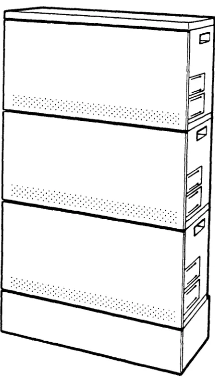
The Electra Professional Level II is a fully digital system serving a maximum of 56 outside (CO/PBX, DID, Tl/FTl, and Tie) lines and a maximum of 56 terminals. The Electra Professional Level II Advanced system serves a maximum of 64 outside lines and a maximum of 96 terminals. Both systems provide for flexible configuration, allowing the customer to purchase only what is needed. The Level II basic cabinet can accommodate a combined total of 40 ports, consisting of outside lines and/or telephones and/or other options. As a customer’s business grows this system can be expanded to accommodate a combined total of 64 ports. The Level II Advanced system basic KSU can accommodate 64 ports. Each of the two available expansion KSUs also support up to 64 universal ports. Additional equipment such as: Single Line Telephones, external speakers, voice mail, facsimile machines, etc., can be connected to these systems to enhance their capabilities. (Figure l-l - Outside View of the Electra Professional Level II KSUs and Figure 1-2 - Outside View of the Electra Professional Level II Advanced KSUs.)
This chapter is designed to provide the technician, installing the Electra Professional Level II or Level II Advanced, a comprehensive explanation of the systems specifications, hardware, and installation procedures. The technician should read this chapter in its entirety before installing the system. This will enable more efficient installation and cut-over.
‘i’.‘.
%‘... ,.:;:;: -
:*:.:+:, ’
p::::::;: _ . . ,_, ::~i:$::::!
December 1993 Level II Advanced
Figure 1-2 Outside View of the Electra Professional Level II Advanced KSUs
1.2 Regulatory Information
The Federal Communications Commission (FCC) has established rules that permit this telephone system to be directly connected to the telephone network. A jack is provided by th&lephone company. Jacks for this type of customer provided equipment will not be provided on party lines or coin lines.
The telephone company may make changes in its technical operations and procedures. If such changes affect the compatibility or use of this system, the telephone company is required to give adequate notice of the changes.
1.2.1 Company Notification
Before connecting this telephone system to the telephone network, the following information must be provided to the telephone company:
1. Your telephone number. 2. FCC registration number:
0 If the system is to be installed as a Key System (no dial access to Tnmk GroupdRoute Advance Blocks) use the following number: Level II System: AY5USA-‘73702-RF-E
Level II Advanced: AY5USA-74750-RF-E
l If the system is to be installed as a Multi-Function System, use the following number:
Level II System: AY5USA-73705-MF-E Level II Advanced: AY5USA-74743-MF-E
3. Facility Interface Codes (FIG), Ringer Equivalence Number (REN), Service Order Codes (SOC), and Jack types are shown in Table l-l - FIC, REN, SOC, and Jack Types for KTUs.
Table l-l FIC, REN, SOC, and Jack Types for KTUs
04DU9-1SN 04DU9-1ZN 04DU9-1SN 04DU9-1ZN
IMPORTANT NOTE
December 1993 Electra Professional Level II & Level II Advanced Installation Service Manual
1.2.2 Battery Disposal
The Electra Professional Level II and/or Level II Advanced systems include the batteries listed in Table l-2 - Battery Types and Quantities for KSUs and KTUs. When disposing of these batteries, KSUs, and/or KTUs, you must comply with applicable federal and state regulations regarding proper disposal procedures.
Table l-2 Battery Types and Quantities for KSUs and KTUs
Unit Name
MIF-F(A)-10 KTU MIF-F(U)-10 KTU
Lithium Lithium
1 1
IMPORTANT SAFEGUARDS FOR BA’M’ERY DISPOSAL
DO NOT PLACE USED BATTERIES IN YOUR REGULAR TRASH! THE PRODUCT YOU PURCHASED CONTAINS A NICKEL-CADMIUM OR SEALED LEAD BATTERY. NICKEL-CADMIUM OR SEALED LEAD BATTERIES MUST BE COLLECTED, RECYCLED, OR DISPOSED OF IN AN ENVIRONMENTALLY SOUND MANNER.
The incineration, landfilling or mixing of nickel-cadmium or sealed lead batteries with the municipal solid waste stream is PROHIBITED BY LAW in most areas. Contact your local solid waste management officials for other information regarding the environmentally sound collection, recycling, and disposal of the battery.
Nickel-cadmium (or sealed lead) batteries must be returned to a federal or state approved nickel-cadmium (or sealed lead) battery recycler. This may be where the batteries were originally sold or a local seller of automotive batteries. In Minnesota call l-800-225PRBA if further disposal information is required, or call l-800-232-9632 for further information.
PRODUCT PACKAGE LABELING
LP
CONTAINS NICKEL-CADMIUM BATTERY.w
MUST BE RECYCLED OR DISPOSED OF PROPERLY. MUST NOT BE DISPOSED OF IN MUNICIPAL WASTE.
Ni-Cd
CONTAINS SEALED LEAD BATTERY. MUST BE RECYCLED OR DISPOSED OF PROPERLY. MUST NOT BE DISPOSED OF IN MUNICIPAL WASTE.
I
Pb1.2.3 Incidence of Harm
If the system is malfunctioning, it may also be causing harm to the telephone network. The telephone system should be disconnected until the source of the problem can be determined and until repair has been made. If this is not done, the telephone company may temporarily disconnect service.
1.2.4 Radio Frequency Interference
In compliance with FCC Part 15 rules, the following statement is provided: IMPORTANT NOTE
“This equipment generates, uses, and can radiate radio frequency energy aid if not installed and used in accordunce with the Installation Service Manual, may cause interference to radio communications. This equipment has been tested and approved for compliance with the limits for a Class A computing device pursuant to Subpart J of Part 15 of FCC Rules, which are designed to provide reasonable protection against such interference when operated in a commercial environment. Operation of this telephone system in a residential area is likely to cause interference, in which ca8e, the user, at his or her own expense, will be required to take whatever measures may be required to correct the interference.”
125 Hearing Aid Compatibility
The NEC Multiline Terminals and NEC Single Line Telephones that are provided for this system are hearing aid compatible. The manufacturer of other Single Line Telephones for use with the system must provide notice of hearing aid compatibility to comply with FCC rules. FCC rules prohibit the use of non-hearing aid compatible telephones (after August 16,1989).
1.2.6 Direct Inward Dialing
Allowing this equipment to be operated in such a manner as to not provide for proper answer supervision is a violation of Part 68 of the FCC’s rules.
December 1993 Electra Professional Level II & Level II Advanced Installation Service Manual
1.2.7
0 A call is unanswered. 0 A busy tone is received. 0 A reorder tone is received.
Voice Announcement/Monitoring Over DID Lines
The use of the Voice Announcement feature to eavesdrop or record sound
activities at the other end of the telephone line may be illegal under certain
circumstances and laws. Consult a legal advisor before implementing any
practice involving the monitoring or recording of a telephone conversation. Some federal and state laws require a party monitoring or recording a telephone conversation to use a beep-tone(s), make notification to all parties to the telephone
conversation an&or obtain consent of allparties to the telephone conversation. In
monitoring or recording sound activities at the other end of the telephone line by -
means of the Voice Announcement feature, the sound of the alert tone at the beginning of the Voice Announcement may or may not be considered sufficient under applicable laws. Some of the applicable laws provide for strict penalties for illegal monitoring or recording of telephone conversations.
1.2.8 Music On Hold
“In accordance with U.S. Copyright Law, a license may be required from the
American Society of Composers, Authors and Publishers, or other similar
organization, if radio or TV broadcasts are transmitted through the Music On
Hold feature of this telecommunication system. NEC America Inc., hereby
disclaims any liability arising out of the failure to obtain such a license. *
1.2.9 Y_
1.2.10
Service Requirements
In the event of equipment malfunction, all repairs should be performed by an authorized agent of NEC America, Inc. or by NRC America, Inc. It is the responsibility of users requiring service to report the need for service to one of NEC America, Inc.‘s authorized agents or to NRC America, Inc.
UL Regulatory Information
Proper answer supervision is provided when either of the following cases exist: A. This equipment returns answer supervision to the Public Switched
Telephone Network (PSTN) and Direct Inward Dialing (DID) calls are: a Answered by the called station.
0 Answered by the Attendant.
0 Routed to a recorded announcement that can be administered by the Customer Premise Equipment (CPE) user.
0 Routed to a dial prompt.
B. This equipment returns answer supervision on all DID calls forwarded to the PSTN. Permissible exceptions are:
CAUTION
IMPORTANT NOTE
This equipment has been listed by Underwriters Laboratories and found to comply with all applicable requirements of the standard for telephone equipment UL 1459 2nd Edition.
Installation Service Manual Electra Professional Level II & Level II Advanced December 1993
1.2.11 DOC Requirements
The Department of Communications (DOC) has established rules that permit this telephone system to be directly connected to the telephone network, Prior to the connection or disconnection of this telephone system to or from the telephone network, the telephone company must be provided with the following information.
1. Your telephone number.
2. DOC registration number: 140 4963 A 3. The Load Number of the equipment: 9
The Canadian Department of Communications label identifies certified equipment, This certification means that the equipment meets certain telecommunications network protective operational and safety requirements. The Department does not guarantee the equipment will operate to the user’s satisfaction.
Before installing this equipment, users should ensure that it is permissible to be connected to the facilities of the local telecommunications company. The equipment must also be installed using an acceptable method of connection. In some cases, the company’s inside wiring associated with a single line individual service may be extended by means of a certified connector assembly (telephone extension cord). The customer should be aware that compliance with the above conditions may not prevent degradation of service in some situations.
Repairs to certified equipment should be made by an authorized Canadian maintenance facility designated by the supplier. Any repairs or alterations made by the user to this equipment, or equipment malfunctions, may give the telecommunications company cause to request the user to disconnect the equipment.
Users should ensure for their own protection that the electrical ground connections of the power utility, telephone lines, and internal metallic water pipe system, if present, are connected together. This precaution may be particularly important in rural areas.
CAUTION
Users should not attempt to make such connections themselves, but should contact the appropriate electric inspection authority or electrician, as appropriate.
The Load Number (LN) assigned to each terminal device denotes the percentage of the total load to be connected to a telephone loop which is used by the device to prevent overloading. The termination on a loop may consist of any combination of devices subject only to the requirement that the total of load numbers of all the devices does not exceed 100.
This equipment has been listed by the Canadian Standards Association and found to comply with all applicable requirements of the standard for telephone equipment C 22.2 No. 225.
This equipment meets DOC requirements CS03.
Use of the LLT-F(BG)-10 KTU has not been approved by the DOC for support of off-premise extensions.
December 1993 Electra Professional Level II & Level II Advanced Installation Service Manual
This digital apparatus does not exceed the Class A limits for radio noise emissions from digital apparatus as set out in the radio interference regulations of the Canadian Department of Communications.
and
Le present appareil numerique n’emet pas de bruits radioelectriques depassant les limites applicables aux appareils numeriques de Classe A prescrites dans le reglement sur le brouillage radioelectrique edicte par le Ministere Des Communications Du Canada.
1.3 Equipment List
The following equipment is available for use in the Electra Professional Level II and Level II Advanced systems. The maximum quantities that can be installed in each system are listed in the following tables.
I
Table 1-3
Equipment Designation
Maximum Quantity/System
Level II KSUs and PSUs
T
I
Description
ESF-SB-10 KSU I
I
Basic KSU with Wall and Floor Mount Brackets I Expansion KSU with Wall and Floor Mount Brackets ~~1
Power Supply Unit
For Battery Backup
Table l-4 Level II Advanced KSUs and PSUs
Equipment Designation
Maximum
Quantity/System Description
ESF-XB-10 KSU I 1 Basic KSU with Wall and Floor Mount, Brackets
ESF-XE-10 KSU r- 2 Expansion KSU with Wall and Floor Mount Brackets 7 PSF-P-20 PSU
Battery
1 for each KSU
2 for each KSU
Power Supply Unit
For Battery Backup
Equipment Designation
CPU-F( j-20 KTU
CLK-F-21 Unit
MMC-F-11 KTU
Table l-5 Common Control KTU Maximum
Quantity/System Level II Advanced Level II
Description
1 1 Central Processing Unit, PBR
4-channel, TNG, CNF, MOH Mounted
1 1 Tl/FTl synchronization unit
piggybacked on CPU-F( l-20 KTU
On CPU-F( j-20 KTU
0 2 Module Memory Controller for Fixed
ESF-XE-10 KSU
Installation Service Manual Electra Professional Level II & Level II Advanced December 1993
Table l-6 Station Interface KTUs
Maximum Equipment
Designation
Quantity/System
Level II Level II
Advanced
Description
ESI-F(8)-21 KTU I__ 7 ~~~ I 12 &channel, 2-wire Electronic Station Interface IInterface SLI-F(8G)-21 KTU
I
6 11 &channel SLTNM Interface with RSG, MW, Interface
PFT (2-channel)
1
LLT-F(BG)-10KTU [ 6 1 22 1 - 2 channel Off-Premise Extension
I
Interface[Table l-7
-
Trunk Interface KTUs
Description
COI-F(4)-20 KTU 7 16
COI-F(8)-20 KTU 7 8
4-channel, Loop or GND Start Trunk Interface 8-channel, Loop or GND Start Trunk Interface
Interface Interface DID-F(4)-10 KTU 1 ~ ~7 1 8 4-channel, DID Line Interface lInterface( TLI-F(2)-10 KTU 1 7 1 16 2-channel, 4-wire E&M Tie Line Interface Interface
Tl/FTl (Fractional Tl) Trunk Interface with Loop and Ground Start Trunk Signaling capability
Tl/FTl (Fractional Tl) Trunk Interface with Loop and Ground Start Trunk Signaling capability, Tie line (E&M), and DID Signaling capability - [Series 300 or higher1
DTI-F( l-10 KTU 1
I I
3 Interface
Interface
DTI-F(A)-20 KTU 1 3
Table l-8
Maximum
Other Optional KTUs
Equipment
Designation Description Slot
PBR-F(4)-11 KTU 1 1 1 2 [4qhannel, DTMF/Push Button Receiver (PBR) 1 Interface
VRS-F(4)-11 KTU 2 2
ECR-F-11 KTU 1 1
MIF-F(S)-10 KTU 1 1
4-channel, Voice Recording Service (VRS) Eight relays for Paging, External Tone Ringers, and Night Chime, two RCA jacks for in/output paging, output ring tone
PC and SMDR Interface
Interface Interface
Option MIF-F(L)-10 KTU 1 1 1 1 PC, SMDR, and LCR Interface
I
OptionACD and MIS Interface 1 Option
MIF-F(A)-10 KTU 1 1
MIF-F(U)-10 KTU 1 1 UCD I_ Option
December 1993 Electra Professional Level II & Level II Advanced Installation Service Manual
Table l-9 Terminals and Optional Units Maximum
Equipment Designation Quantity/System
Level II Description
Level II Advanced
ETW-8-1 (BK) TEL 55 95 8-line non-display with built-in speakerphone, large LED, eight function keys, and ADA compatible ETW-lGDC-1 (BK) TEL 56 96 16-line Display Compact with built-in speakerphone,
large LED, eight function keys, and ADA compatible ETW-16DD-1 (BK) TEL 56 96 16-line Display Deluxe with built-in speakerphone,
large LED, eight function keys, 20 programmable One-Touch keys with red LEDs, and ADA compatible ETW-24DS-1 (BK) TEL 56 96 24line Display Special with built-in speakerphone,
dual path capability, large LED, eight function keys, 12 programmable One-Tauch keys, and ADA compatible
EDW-48-( 1 (BK) Console 4 4 48-line Attendant Add-On Console with 12 function keys
ADA(l)-W (BK) Unit 56 96 Ancillary Device Adaptor (for connection of headset, recording interface, external speakerphone)
ADA(P)-W (BK) Unit 16
(See Note) (See’!oteJ Ancillary Device Adaptor (for connection of an SLT, modem, answering machine, or fax)
WMU-W (BK) Unit 56 96 Wall Mount Unit
SLT-F(lG)-10 ADP 55 95 l-channel Single Line Telephone Adaptor
Note: The recommended maximum is 16 ADA(B)-W (BK) Units, however, additional units can be installed depending on system traffic and the number of PBR circuits available.
1.4 Equipment General Information
One Electra Professional Level II and Level II Advanced Job Specifications Manual (Stock
No. 722024) is included with the CPU-F( J-20 KTU. All optional equipment: external
amplifiers, Music On Hold source, Background Music source, external speakers, etc.,
must be locally provided. 1.5 Equipment Description
1.5.1 Level II Key Service Units and Power Supply Units ESF-SB-10 KSU
Y_ The Key Service Unit (KSU) of the Electra Professional Level II system provides service for outside lines, Attendant Add-On Consoles, and interconnection of Multiline Terminals. The basic KSU provides 40 ports and can be expanded to 64 ports with an expansion module. A PSF-S-20 PSU (Power Supply Unit) and backup batteries are included with this KSU.
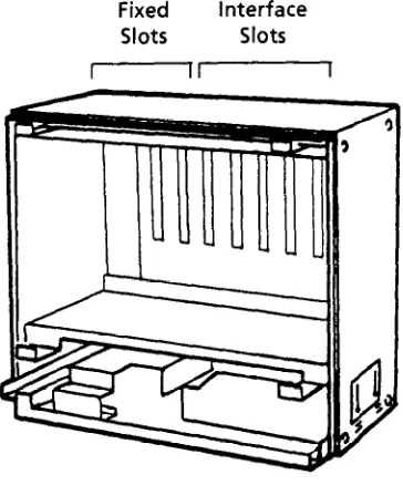
Fixed slots are intended for the CPU and MIF KTUs. The remaining interface slots are intended for 2-, 4-, or 8-channel KTUs: ESI, SLI, COI, DID, TLI, PBR, VRS, ECR, LLT, DTI. (Only one DTI can be installed. It must be installed in the first interface slot.)
Installation Service Manual
December Electra Professional Level II & Level II Advanced ESF-SE-10 KSU
This expansion unit provides for an additional 24 ports that can accommodate up to three KTUs.
This KSU is designed to accommodate 2-, 4-, or 8-channel interface cards. A PSF-S-20 PSU (Power Supply Unit) and backup batteries are included with this KSU.
PSF-S-20 PSU
This power supply unit is provided with both the basic and expansion KSUs. It has a backup interface, accepts 117 Vat and outputs + 5V, -5V, and -24V to the system.
1.5.2 Level II Advanced Key Service Units and Power Supply Units ESF-XB-10 KSU
The Key Service Unit (KSTJ) of the Electra Professional Level II Advanced system provides service for outside lines, Attendant Add-On Consoles, and interconnection of Multiline Terminals. The basic KSU provides 64 ports and can be expanded in 64 port increments up to 192 ports with expansion modules. PSF-P-20 PSU (Power Supply Unit) and backup batteries are included with this KSU.
Fixed slots are intended for the CPU and MIF KTUs. The remaining interface slots are intended for 2-, 4-, or &channel KTUs: ESI, SLI, COI, DID, TLI, PBR, VRS, ECR, LLT, DTI. (Up to three DTI KTUs can be installed.)
ESF-XE-10 KSU
This Level II Advanced system expansion unit provides for an additional 64 ports that can accommodate up to 8 KTUs. Fixed slots are intended for the MMC and MIF KTUs.
This KSU is designed to accommodate 2-, 4-, or S-channel interface cards. PSF-P-20 PSU (Power Supply Unit) and backup batteries are included with this KSU.
PSF-P-20 PSU
This power supply unit is provided with both the basic and expansion KSUs. It has a backup interface, accepts 117 Vat and outputs + 5V, -5V, and -24V to the system.
1.5.3 Common Control Key Telephone Unit CPU-F( j-20 KTU
?_
The Central Processing Unit KTU contains a Is-bit microprocessor which has overall control of the system. This KTU provides an advanced feature package for the Electra Professional Level II and Level II Advanced system user. Included with this KTU are six, 4-party conference circuits, PBR (four channels are included), TNG, MOH input, and a built-in music source.
CLK-F-21 Unit
The CLK-F-21 (Clock) Unit provides synchronization for a Tl line that is connected to the system. This unit is attached to the CPU-F( l-20 KTU and works in conjunction with the DTI-F( j-10 KTU or DTI-F(A)-20 KTU.
One CLK-F-21 Unit can be installed in the system.
December 1993 Electra Professional Level II & Level II Advanced Installation Service Manual MMC-F-11 KTU
The Module Memory Controller, with a 4-bit microprocessor and Controller Unit, is required for each ESF-XE-10 KSU used in the Level II Advanced system. It controls data transmission between the CPU-F( j-20 KTU and the interface cards installed in the ESF-XE-10 KSU. A maximum of two MMC-F-11 KTUs can be installed in the fixed slots.
1.5.4 Station Interface Key Telephone Units ESI-F(8)-21 KTU
This Electronic Station Interface KTU contains eight circuits, each of which can support any type Multiline Terminal, EDW-48-c 1 (BK) Console, or an SLT Adaptor.
A maximum of seven ESI-F(8)-21 KTUs can be installed in interface slots in the Level II system and a maximum of 12 in the Level II Advanced system.
SLI-F@G)-21
KTU
The Single Line Interface KTU can support eight Single Line Telephones and/or voice mail ports. This KTU provides Ringing Signal Generator (RSG), Power Failure Transfer (PFT), and Message Waiting (MW) LED voltage to the Single Line Telephones.
A maximum of six SLI-F(8G)-21 KTUs can be installed in interface slots in the Level II system and a maximum of 11 in the Level II Advanced system.
LLT-F(SG)-10
KTU
The Long Line Telephone (LLT) KTU provides for the termination and operation of up to two Off-Premise Extensions (OPX). Each LLT-F(BG)-10 KTU has a built-in ringer (RSG). Up to 3000 ohms of loop resistance (including the Single Line Instrument) is acceptable between the LLT-F(PG)-10 KTU and SLT. - A maximum of six LLT-F(OG)-10 KTUs can be installed in interface slots in the Level II system and a maximum of 22 in the Level II Advanced system.
1.5.5 Trunk Interface Key Telephone Units COI-F(4)-20 KTU
This Central Office Interface KTU complies with UL 1459 2nd Edition requirements. Electrical fuses (posistors) are built into this KTU. The COI-F(4)-20 KTU supports four outside (COIPBX) lines and provides circuitry for ring detection, holding, and dialing. The outside lines can be any combination of Loop or Ground start, DTMF, or Dial Pulse dialing trunks. A maximum of seven COI-F(4)-20 KTUs can be installed in interface slots in the Level II system and a maximum of 16 in the Level II Advanced system.
COI-F(8)-20 KTU
This Central Office Interface KTU complies with UL 1459 2nd Edition requirements. Electrical fuses (posistors) are built into this KTU. The COI-F(8)-20 KTU supports eight outside (CO/PBX) lines and provides circuitry for ring detection, holding, and dialing. The outside lines can be any combination of Loop or Ground Start, DTMF, or Dial Pulse dialing trunks. A maximum of seven COI-F(8)-20 KTUs can be installed in interface slots in the Level II system and a maximum of eight in the Level II Advanced system.
Installation Service Manual Electra Professional Level II & Level II Advanced December 1993
DID-F(I)-10 KTU
The Direct Inward Dialing interface KTU complies with UL 1459 2nd Edition requirements. The DID-F(4)-10 KTU supports the termination and operation of up to four DID lines. Electrical fuses (posistors) are built into this KTU. Immediate start, wink start, and delay dial are accommodated. Dial Pulse and DTMF are supported.
A maximum of seven DID-F(4)-10 KTUs can be installed in interface slots in the Level II system and a maximum of eight in the Level II Advanced system. TLI-F(2)-11 KTU
This Tie Line Interface KTU supports the termination and operation of up to two E&M Tie Lines (4-wire, type I and type V, and lo/20 pps Dial Pulse or DTMF). Immediate or wink start, delay start, or second dial tone signaling is accommodated.
A maximum of seven TLI-F(B)-11 KTUs can be installed in interface slots in the Level II system and a maximum of 16 in the Level II Advanced system.
DTI-F( j-10 KTU
The Digital Trunk Interface (DTI) KTU provides for the termination of a Tl/Fractional Tl (24 DS-0 channels or fewer) line. The DTI-F( )-lo KTU contains circuitry for outside ring detection, holding, dialing, and control functions.
A combination of Loop and Ground Start Trunks can be used on this DTI KTU. DTMF or Dial Pulse dialing is also supported.
The two interface slots to the right of this KTU may need to be left vacant depending on System Programming. A CLK-F-21 Unit must be connected to the CPU-F( J-20 KTU.
One DTI-F( J-10 KTU or DTI-F(A)-20 KTU can be installed in the Level II system and three in the Level II Advanced system.
* DTI-F(A)30 Kl’U
This Digital Trunk Interface (DTI) KTU includes the functions of the DTI-F( )-lo KTU in addition to Tie line (E&M) and DID signaling capabilities. (Available with Series 300 or higher.)
A combination, in groups of four, of Loop and Ground Start Trunks, Tie line, or DID Trunks can be used on this DTI KTU. DTMF or Dial Pulse dialing is also supported.
2^ The two interface slots to the right of this KTU may need to be IeR vacant depending on System Programming. A CLK-F-21 Unit must be connected to the CPU-F( J-20 KTU.
One DTI-F( j-10 KTU or DTI-F(A)-20 KTU can be installed in the Level II system and three in the Level II Advanced system.
December 1993 Electra Professional Level II & Level II Advanced Installation Service Manual
1.5.6 Optional Key Telephone Units ECR-F-11 KTU
The External Control Relay (ECR) KTU provides common audible tone signaling with relay contacts for external ringing equipment and an audible output for External Paging Systems. Eight relays are provided, four for External Tone Ringer control, one for Night Chime, and three for External Paging.
One ECR-F-11 KTU can be installed in either system. PBR-F(4)-11 KTU
The Push Button Receiver KTU detects and translates DTMF tones generated only by Single Line Telephones, modems, or facsimile machines. The PBR-F(4)-11 KTU provides four circuits.
The Level II interface slots can accommodate one PBR-F(4)-11 KTU for a maximum of eight circuits per system with a CPU-F( l-20 KTU, and two PBR-F(4)-11 KTUs in the Level II Advanced system for a maximum of 12 circuits.
VRS-F(4)-11 KTU
The Voice Recording Service KTU provides voice recording messages for internal stations, automatic answering of incoming CO/PBX calls, and Delay Announcement messages for ACD/UCD by a voice recorded message. The PBR circuits on the CPU-F( l-20 support the VRS-F(4)-11 KTU when it is installed. A maximum of two VRS-F(4)-11 KTUs can be installed in any of the systems interface slots providing eight channels.
MIF-F(S)-10 KTU
The Multipurpose Interface KTU provides two capabilities. First, it generates detailed call records of incoming, outgoing, conference, and transferred outside calls. Reports include digits dialed, call duration, trunks used, etc. Secondly, this KTU also allows interfacing between a personal computer, with the PC software programming package, and the CPU-F( l-20 KTU for programming System Data and up/down loading System Data.
One MIF-F(S)-10 KTU can be installed in the option slot or any of the first four interface slots (IFl/OPl - IF4/OP4) provided in the ESF-SB-10 KSU, the ESF-XB-10 KSU, or the first ESF-XE-10 KSU installed.
MIF-F(L)-10 KTU
The MIF-F(L)-10 KTU provides three features: it allows the connection of a personal computer for performing System Programming and up/down loading of System Data, provides Station Message Detail Recording (SMDR) to be output via an RS-232 cable to a printer, and provides Least Cost Routing (LCR) capability.
One MIF-F(L)-10 KTU can be installed in the option slot or any of the first four interface slots (IFl/OPl - IF4/OP41 provided in the ESF-SB-10 KSU, the ESF-XB-10 KSU, or the first ESF-XE-10 KSU installed.
Refer to the Electra Professional Level ZZ and Level ZZ Advanced Least Cost
Routing Manual (included with the LCR software) for LCR instructions.
MIF-F(A)-10 KTU
The MIF-F(A)-10 KTU provides the Automatic Call Distribution (ACD) feature and an interface to an MIS terminal.
One MIF-F(A)-10 KTU can be installed in the option slot or any of the first four interface slots (IFl/OPl - IF4/OP4) provided in the ESF-SB-10 KSU, ESF-XB-10 KSU, or the first ESF-XE-10 KSU installed.
MIF-F(U)-10 KTU
The MIF-F(U)-10 KTU provides the Uniform Call Distribution (UCD) feature. One MIF-F(U)-10 KTU can be installed in the option slot or any of the first four interface slots (IFl/OPl - IF4/OP4) provided in the ESF-SB-10 KSU,ESF-XB-10 KSU, or the first ESF-XE-10 KSU installed.
Note: Only one MIF-F(A)-10 KTU or MIF-F(U)-10 KTU can be installed in the system.
1.5.7 Multiline Terminals and Associated Equipment ETW-8-l (BK) TEL
This Multiline Terminal is a fully modular instrument with eight Flexible Line keys (each with a two-color LED), eight function keys, built-in speakerphone, ADA compatibility, and a large LED to indicate incoming calls and messages. A maximum of 55 ETW-8-1 (BK) TELs can be installed in a Level II system and 95 in a Level II Advanced system.
ETW-16DC-1 (BK) TEL
This Multiline Terminal is a fully modular instrument with 16 Flexible Line keys (each with a two-color LED), eight function keys, built-in speakerphone, a 16-character Liquid Crystal Display (LCD), ADA compatibility, and a large LED to indicate incoming calls and messages.
A maximum of 56 ETW-16DC-1 (BK) TELs can be installed in a Level II system and 96 in a Level II Advanced system.
ETW-16DD-1 (BK) TEL
This Multiline Terminal is a fully modular instrument with 16 Flexible Line keys (each with a two-color LED), eight function keys, built-in speakerphone, a 16-character Liquid Crystal Display (LCD), 20 programmable One-Touch keys with red LEDs, ADA compatibility, and a large LED to indicate incoming calls and messages.
2^ A maximum of 56 ETW-16DD-1 (BK) TELs can be installed in a Level II system and 96 in a Level II Advanced system.
ETW-24DS-1 (BK) TEL
This Multiline Terminal is a fully modular instrument with 24 Flexible Line keys (each with a two-color LED), eight function keys, built-in speakerphone, dual path capability, 12 programmable One-Touch keys, ADA compatibility, and a large LED to indicate incoming calls and messages.
A maximum of 56 ETW-24DS-1 (BK) TELs can be installed in a Level II system and 96 in a Level II Advanced system.
December 1993 Electra Professional Level II & Level II Advanced Installation Service Manual EDW-4%( ) (BK) Console
The Attendant Add-On Console is equipped with 48 programmable keys with two-color (red and green) LED indications and 12 function keys with one-color (red) LED. The 48 programmable keys can be assigned as Direct Station Selection keys, function keys, or outside line keys.
A maximum of four EDW-4%( ) (BK) Consoles can be installed in either system. ADA(l)-W (BK) Unit
The ADA(l)-W (BK) Unit (Ancillary Device Adaptor) provides the Multiline Terminal with connection for a headset, external speakerphone, tape recorder, or other ancillary devices. An ADA(l)-W (BK) Unit can be installed in any Multiline Terminal.
A maximum of 56 ADA(l)-W (BK) Units can be installed in a Level II system or 96 in a Level II Advanced system, one per Multiline Terminal.
ADAO)-W (BK) Unit
The ADA(B)-W (BK) Unit (Ancillary Device Adaptor) provides the Multiline Terminal with connection for a cordless Single Line Telephone, modem, facsimile, or answering machine. An ADA (2)-W (BK) Unit can be installed in any Multiline Terminal.
The recommended maximum is 16 ADA(B)-W (BK) Units, however, additional units can be installed depending on system traffic and the number of PBR circuits available.
WMU-W (BK) Unit
The WMU-W is a universal Wall Mount Unit which can be used to mount any Multiline Terminal.
1.5.8 Single Line Telephone Adaptor SLT-F(lG)-10 ADP
This Single Line Telephone Adaptor provides an interface for a Single Line Telephone or similar device from an ESI-F(8)-21 KTU channel.
A maximum of 55 SLT-F(lG)-10 ADP adaptors can be installed in a Level II system and a maximum of 95 in a Level II Advanced system.
SECTION 2 SYSTEM SPECIFICATIONS 2.1 General Information
Thefollowing diagrams and tables show specifications for the Electra Professional Level II and Level II Advanced systems. The technician should review these carefully before attempting to install the systems.
December 1993
2.2 System Block Diagram
The system block diagram shows a conceptual representation of an installed system. (Refer to Figure l-3 - System Block Diagram. Also refer to Table l-10 - Abbreviations for a list of abbreviations used in the system block diagram.)
Table l-10 Abbreviations
December Electra Professional Level II & Level II Advanced Installation Service Manual
I I I
ESI (8) I
I I
I I
I
SLT SLI (8G) I
I
0 I I
FAX
I 2w SLI (8G) ; 0
, I I
ECR I
I 1’ I
ESI (8) I
I I
SLT LLT(2G) ;
1 I f
^_____________________________,--J
I
DSW
I I l-___-
I
CLK II I
~~~~~, I I
2w
DID (4) DIDTrunk
I
On Hold Source
Numbers in ( ) designate the number of channels supported when using the equipment listed.
Figure 1-3 System Block Diagram
2.3 System Control Capacities
The control capacities of the system are shown in Table l-11 - System Control Capacities. Table l-11
Item
Slot
11
Number of Outside Lines
I
COPBXI
DIDI
E&M TlSystem Control Capacities
Level II Level II Advanced
Basic Expansion Basic + Basic Expansions Basic + 2
Unit
5 8 8 24
1 1 2 4
32 56 56 64 N/A
32 56 56 64 co1
16 28 28 32 DID
8 14 14 32 TLI
Note 1: The number of Attendant Add-On Consoles is included in the number of Multiline Terminals. Note 2: Four of the eight channels are accommodated in the CPU.
December 1993
Electra II & Level II Advanced btallation Service Manual
2.4 Cabling Requirements
2.4.1 Cabling Specifications
The KSU is connected with each of the Multiline Terminals and Single Line Telephones by a separate twisted l-pair cable or 2-pair cable (only for Multiline Terminals). Table 1-12 - Multiline Terminal Loop Resistance and Cable Length and Table 1-13 - Single Line Telephone Connection Cable Length show the cables used for wiring between the KSU and individual terminals or adaptors. Table 1-12 Multiline Terminal Loop Resistance and Cable Len&h
Terminal or Adaptor
Maximum
I I I
ETW-8-1 (BK) TEL 61 600 1500
I I I
ETW-16DC1 (BK) TEL 46 450 1300
ETW-16DD-1 (BK) TEL 37 360 820
ETW-24DS1 (BK) TEL 46 450 820
EDW-48-t 1 (BK) Attendant Add-On Console 102 1000 2000
with AC Adaptor
SLT-F(lG)-10 ADP 61 600 1200
Note 1: Note 2: Note 3:
When installing an Attendant Add-On Console, the use of an AC Adaptor is required.
The length for the specified SLT Adaptor is the length between the ES1 KTU and the SLT - Adaptor.
When additional length is required between the ES1 and a Multiline Terminal, Attendant Add-On Console, or SLT Adaptor, use twisted a-pair cable as shown in Figure 1-4 Connecting the ES1 to the Multiline Terminal Using Twisted 2-Pair Cable.
Twisted 2-pair cable
Multiline Terminal
Figure l-4 Connecting the ES1 to the Multiline Terminal Using Twisted a-Pair Cable
Table 1-13 Single Line Telephone Connection Cable Length
Connected Equipment Cable
Maximum Loop Resistance (24 AWG) from Connected
Equipment to Telephone SLI-F(8G)-21 KTU
LLT-F(PG)-10 KTU SLT-F(lG)-10 ADP
Twisted l-pair Twisted l-pair Twisted l-pair
300 ohm 1500 ohm
300 ohm
ADA(B)-W (BK) Unit I Twisted l-pair I 10 feet I
Note: Mixing digital and analog ports through the same 25pair cable runs is not recommended.
The following types of cabling are required for the equipment listed below: 0 Music Source (for MOH and BGM inputs): Hi-Fi Shielded Audio Cable 0 External Amplifier: Hi-Fi Shielded Audio Cable 2.4.2 Cabling Precautions
When selecting cables and Main Distribution Frames (MDF), future expansion or assignment changes should be given due consideration. Avoid running cables in the following places:
0 A place exposed to wind or rain.
0 A place near heat radiating equipment or where the quality of station cable covering could be affected by gases and chemicals.
0 An unstable place subject to vibration. 2.5 Power Requirements
2.5.1 Power Supply Inputs
AC Input (PSF-S-20 PSU or PSF-P-20 PSU): 0 117 Vat f 10%
0 6OHs + 10% 0 Single Phase
0 1.5A maximum current
0 A dedicated outlet, separately fused and grounded, is required. --
2.5.2 Power Supply Outputs Table
Table 1-14 Power Outputs
Level II Level II Advanced DC
Voltage Minimum Maximum Minimum Maximum
Current Current Current Current
- 24V 0.3A 5.9A 0.3A 7.5A
+ 5v 0.3A 4.3A 0.3A 6.5A
-5v OA 0.8A OA 1.2A
2.5.3 Power Consumption and Dissipation Table
Table 1-15 Power Consumption and Dissipation Maximum
Module RMS Watts Used Watts Used
Current (Idle) (Maximum)
IB
asicI
1.3A 1 120 I 150 ILevel II I
Basic + Expansion 1.9A 180 220
,
I
Level II Basic 1.9A 180 220( Advanced 1 B asic + 2 Expansions I 5.7A I 540 I
I 660 I -
2.5.4 Fuse Replacement Table
Table 1-16 Fuse Replacement Unit
PSF-S-20 PSU
PSF-P-20 PSIJ
Fuse No. Fl F2 Fl F2
Specifications 125V, 4.OA 125V, i’.OA 125V, 6.3A 25OV, 12.OA
Description AC Input DC Input AC Input DC Input
Dimensions 114” x l-114” l/4” x l-114” 114” x l-114” l/4” x l-114” Note: All fuses are normal blown glass tube. Do not use slow blow fuses.
Installation Service Manual
ZeDecember Electra Professional Level II & Level II Advanced 1993
2.6 Environmental Conditions 0 Temperature
1. Operating: 50°F - 104°F (10°C - 104°C) 2. Recommended Long Term: 50°F - 90”F(lO”C - 32.2”C) 0 Operating Humidity: 10% - 90% noncondensing 2.7 Outside Line Types
0 2-wire, Loop Start or Ground Start Trunks
0 a-wire, Loop Dial, DID Lines (Dial Pulse or DTMF)
0 4wire, E & M Tie Lines (Type I or V, Dial Pulse, or DTMF)
0 Digital Trunk Tl/FTl (Loop Start or Ground Start, Tie Line (E&M), or DID Signaling)
2.8 Network and Control Specifications 2.81 Transmission
0 Data Length:
From Multiline Terminal to ESI-F(8)-21 KTU: 23 bits From ESI-F(8)-21 KTU to Multiline Terminal: 23 bits 0 Data Transmission Rates:
Between ESI-F(8)-21 KTU and Multiline Terminal: 184K bits/set. (voice and signaling) 0 Scanning Time for each Multiline Terminal: 32 ms.
Network
0 TDM Switching: PCM (p Law) 0 TDM Clock: 2.048 MHz 0 TDM Data Bus: 8 bit 0’ TDM Timeframe: 125 us. Control
0 Control: Stored program with distributed processing 0 Central Processor: Is-bit microprocessor
0 Clock: 8 MHz
0 Interface KTU: 4-bit microprocessor 0 Optional KTUs (MIF and DTI): 8-bit microprocessor l Multiline Terminal and
Attendant Add-On Console: 4-bit microprocessor 0 SLT Adaptor: 4-bit microprocessor 2.8.2
2.8.3